Watnext WatHome20 Series User manual

Overcounter and undercounter water coolers
WatHome20
Instruction manual
WatHome20Up, WatHome20In

Product models
WatHome20Up // Overcounter sparkling water cooler
WatHome20In // Undercounter sparkling water cooler
IMPORTANT: Read carefully the instruction manual and safety
procedures before carrying out the installation of the dispenser
Always leave this document ready for use close to the dispenser
All rights reserved.
No part of this document can be printed, copied or published in any way
before obtaining written approval from the producer. The same is valid for
numbers and figures.
The information given into this document are based on general data
known by the producer at the time of the publishing of the document,
concerning construction, materials characteristics and working methods,
therefore this document can be adapted at any time. This is why, these
instructions are only to be considered as general guidelines for the
installation, the use and the maintenance of the dispenser.
This document is only valid for the standard version of the dispenser,
therefore the producer is not responsible for damages due to devices sold
with different technical specifications from standard version.
The instruction manual has been edited with care and attention; however,
the producer cannot be considered responsible for any error or oversight
that could be contained in the document or for any consequence
originated by these oversights.
Watnext Industries srl
Via Malta 2/8 - 16121 Genova (ITALY)
+39 010 776 6296
info@watnext.it
watnext.it

General
instructions ... 02
Use of the following instruction
manuale ... 02
Pictograms and symbols ... 02
Customer service and technical
support ... 03
Law regulations ... 03
Safety information ... 04
Safety warnings ... 04
Safety precautions ... 04
Technical data ... 05
Technical data ... 05
Description of components ... 05
Producer data ... 06
Warranty ... 06
Warranty exclusions ... 06
Builder responsibilities ... 07
Unpacking ... 09
Firsy check of supplied
material ... 09
Unpacking of supplied
material ... 09
Visual examination ... 10
Installation ... 11
Installation location ... 11
Dispenser cleaning ... 11
Dispenser placing ... 11
Connection and duty
start ... 13
Connection to water supply ... 13
Connection with power
supply ... 14
Connection with CO₂ cylinder ... 14
Regulation of CO₂ and
temperature ... 15
Management procedures for the
dispenser ... 16
Maintenance ... 18
Regular maintenance ... 18
Malfunctioning, causes, seek-out,
interventions ... 20
Law regulations for
disposal ... 22
Dismantling dispenser ... 22
Disposal of expired material ... 22
Disposal of electric material waste
WEEE ... 22
Electrical system ... 24
Form I
Dispenser duty start form ... 25
Form III
Regular maintenance form ... 26
Form III
Extraordinary maintenance
form ... 27
Index
02
1. General instructions
Use of the following instruction manual
Please read the safety rules before using the dispenser
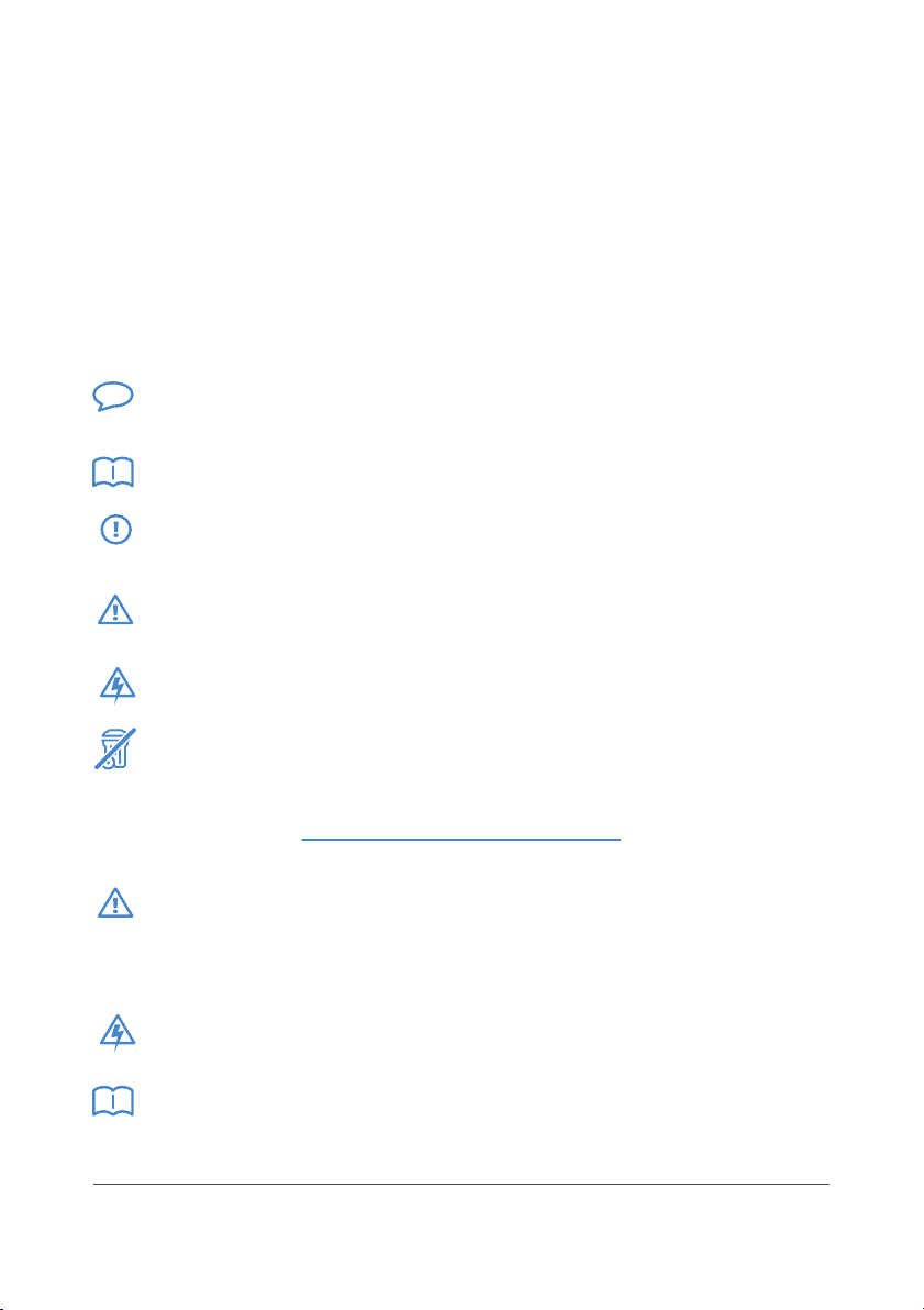
Pictograms and symbols
This manual includes following symbols and pictograms:
Suggestion Suggestion and advices to complete procedures in a
simple way
Read Read safety instructions
Beware Procedures that can lead to harm for the dispenser or
surroundings if not followed with due attention
Danger Procedures that can lead to harm for the dispenser or
people if not followed with due attention
Danger Electrical power
Crossed bin Do not dispose electric material in generic trash. Please
ask about the disposal of electric material to authorities in charge in
your country
Danger In case of use of this dispenser by children or persons with
physical or mental reduced capacity, or without experience or
knowledge of the dispenser, the supervision of a specialist is
mandatory. Children should not play with the dispenser
Beware Operations and fixing on electrical system and refrigerating
system are to be permitted only to specialized and authorized staff
Introduction Before using the dispenser, please read carefully the
instruction manual!

03
Customer service and technical support
Get in touch with the reseller for any information concerning specific
settings, maintenance or necessary fixing that are not included in
following manual. The reseller is always the most appropriate contact to
get the assistance you need.
Please be sure to have following data available:
• Dispenser model name
• Dispenser serial number
You can find these information on label afflixed on the dispenser.
Law regulations
Laws concerning potable water treatment systems in Italy are: ministerial
decree 06.04.2004, n.174 art. 9 – legislative decree n.31 of 2011 and
ministerial decree of 07.02.2012 n.25.
This user manual that comes along with the dispenser is divided in many
sections that analyze and explain all the correct procedures that must be
carried out to maintain a good performance level of the dispenser. It also
explains possible health and safety risks for technicians and final user if
the procedures given are not adopted.
This user manual is addressed to all the “downstream” subject who use
the water dispenser:
• Professionals that take care of transport, stocking, sale, installation,
use and maintenance (preventive, ordinary, extraordinary) from the
entrance into the market to its final dismantlement.
• Direct users
This user guide for installation, assembling, use and maintenance of
dispensers must follow with each device that enters into the market
(ministerial decree 07.02.2012 n.25 art. 6 comma b).

04
2. Safety informations
Safety warnings
• Do not place the dispenser on inclined surface, pillows, carpets,
raised floor or shelf
• Only use potable water from water network. Do not use with water
coming from wells, rain deposit, rivers and sea water.
• Do not use hot water
• Use the dispenser in clean locations.
• Do not use the dispenser with temperatures below 4°C
• Do not use tubing longer than 3 meters
• Do not pull on tubing to move the dispenser
• Avoid exposing the dispenser to sun rays or high temperatures
• Properly clean the dispenser periodically (see concerning chapter)
• Avoid leaving heating systems or flammable substances near the
dispenser
• Do not open or alter the dispenser
• In case of water leakage, close the main valve and call for
maintenance
• The dispenser should not be used by children
Safety precautions
• Keep top parts closed during the use of the dispenser
• If filters have been placed, replace them periodically following
producer recommendations.
• Flow water for at least 5 minutes after long periods of inactivity of
the dispenser, and after every change of filter
• Only use suggested materials for internal cleaning (see chapter
concerning periodic maintenance)
• Do not move the dispenser if water is flowing
• Only use on potable water
• Avoid storing water in bottles for too long

05
1
2345
3. Technical data
Technical data
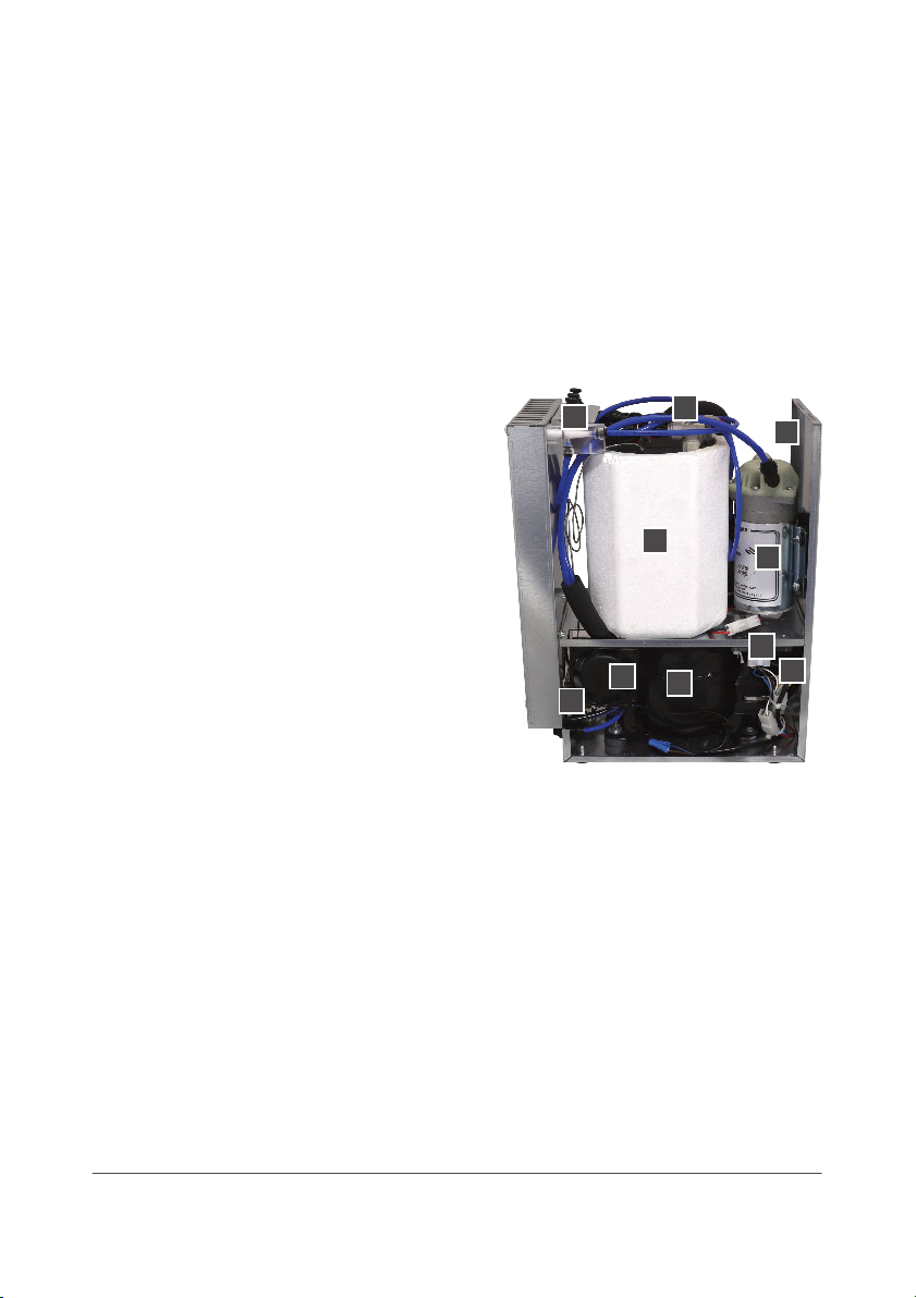
Description of components
The dispenser is formed by following main components (see picture
below)
1. Condensator
2. CO₂ inlet 6 mm tubing
3. H₂O inlet 8 mm tubing
4. Thermostat
5. IEC power plug On-Off
6. Ambient water
7. Cold water
8. Sparkling water
9. Drain grid
10. Ambient Water outlet
8 mm
11. Cold water outlet 8 mm
12. Sparkling water outlet
8 mm
Size 18x47x42 cm
Weight 12 Kg
Power supply 230 V AC
Total power absorption 220 W
Thermal power 15 l/h
Compressor 156 Watt (ΔT = 10°C)
Coil Stainless steel AISI 304
Water pump 65 W
Fittings Metric 8-6 mm
Hermetic saturator With internal cooling 1,5 l
9
6
7
8
1
12
2
11
3
10
45

06
Producer data
The main data of the dispenser are displayed in the label affixed on the
back or on one side of the dispenser, but also on the back cover of this
user manual.
Data available on the label:
• Producer
• Dispenser model
Important in case of alteration or loss of producer label the warranty
is no longer valid
Warranty
Watnext industries srl covers in warranty the dispenser for 12 (twelve)
months from the day of invoice issue to the authorized reseller, that will
grant in its turn a legal warranty to end user.
Warranty covers any deficiency of manufacture and construction.
Watnext industries srl commits with replacing or repairing free of charge
at its headquarters in Genova (ITALY) any component that, following also
customer judgement, could be defective. Malfunctions due to usury are
not included in the warranty. In the event that a technical support was
needed from Watnext industries srl specialized personnel for an on-site
maintenance service, the cost for stay will be charged to end user. Free of
charge supply of spare parts covered by warranty is always consequent to
defective parts oversight from producer (or authorized third parties)
Warranty do not cover components subject to usury (filters, pumps,
faucets and mixer taps, pressure regulators, water meters, co2
bottles,ecc..). It also cannot cover defect caused by normal usury or
inappropriate use of the dispenser.
N.B. a technical support for repair will only postpone the warranty on
replaced or repaired component
Warranty exclusions
Warranty will not cover damages coming from negligence or different
use of the dispenser, for example:

07
• Transport
• Negligence
• Inappropriate or unadapted use of the dispenser
• Different use from the one specified in this user manual
• Wrong power connection or electric shock due to atmospheric
agents
• Uncorrect installation, carried out by unauthorized personnel
• Natural events, calamities
• Maintenance support (ordinary or extraordinary)
• Repairs carried out by unauthorized or unqualified technical
personnel
• Each alteration that hasn’t been previously approved by Watnext
industries srl
• Use of spare parts or equipment not directly supplied or approved
by Watnext industries srl
• Alteration or loss of producer label
• Disrespect of instructions given for the installation or unauthorized
alteration
Builder responsibilities
In order to be covered by warranty given by the producer, the end user
must comply with precautions given in this user manual.
Some basic rules that must be followed:
• The installation must be carried out by specialized and authorized
professionals following the instructions given in the user manual
• For ordinary maintenance the specialized professional must only
use authorized spare parts
Watnext industries srl refuses any responsibility in case unauthorized
spare parts have been used.
Only with authorized spare parts Watnext industries srl can guarantee the
conservation of best water features to final user:
• Avoid overloading the dispenser (check working limits)
• Do not unplug the dispenser from power supply while water is
flowing

08
• The installation should be done in adequate location (avoiding hot
sources, far from children reach, not exposed to sun rays and with
good flow of air to permit aeration)
Builder declines any direct or indirect responsibility that could be due to:
• Installation done by non professionals
• Maintenance done by non professionals
• Use of inadequate or unauthorized components
• Disrespect of instructions given in this user manual
• Installations uncompliant with specific law regulations that have to
be applied in country of destination
• Modifications (substantial or non substantial) carried out on the
dispenser, on software, on hardware and operations logics, unless
previously authorized
• Unauthorized repairs, carried out by non specialized professionals

4. Unpacking
Warning always check first shipping data (delivery address,
destination, package quantity, order number, dispenser model and
code, ecc..)
Firsy check of supplied material
The dispenser must always travel in vertical position. If
the dispenser is delivered lying down or upside down,
or on its side, the dispenser should be returned, as
there is a high chance that the ice-bank will be
irreparably compromised. It should be left in upside
position at least 2 hours, then put it on test bench to
check if it can work.
The packed dispenser must look intact. It should not
show impact signs, breakage signs, crumpled
cardboard, rips..
It should not show alteration signs.
Is should not show traces for having remained under rain, snow, cold, low
temperatures ecc..
Any sign on the box could cause problems with the regular functioning of
the dispenser.
Danger the dispenser, like every other dispenser with ice bank, must
compulsorily travel and be stocked in vertical position. Laying down
or turning upside down the dispenser can lead to irreversible
damages to cooling circuit
At the moment of delivery, check that the dispenser traveled in vertical
position – that is to say if it traveled on a pallet.
Unpacking of supplied material
After the preliminary check has been carried out, you can proceed with
the unpacking of the dispenser. Please respect the arrow sign placed on
the cardboard. This is the procedure to remove the dispenser from its box:
• Cut the safety plastic strapping (if any)
09
• Open the upper part of the box (be careful using cutter)
• Remove Styrofoam, bubble wrap or paper used to protect the
dispenser
Carefully examine the dispenser looking for possible damages. If any,
please inform immediately the courier and the supplier.
Important leave packing material far from children’s reach
Suggestion store packing material and boxes. They can be useful for
future shipping of the dispenser to service center
Visual examination
The body of the dispenser (chassis) must result intact visually and in
perfect conditions.
Important Watnext industries srl follows rigid and detailed control
procedures before the shipping
10

5. Installation
Installation location
The location where the dispenser is placed should have following
features:
• Temperature between +4°c and +35°C
• The aeration must be sufficient to allow good performances of
cooling systems
• Max Humidity 80%
• Following ministerial decree 25, the dispenser should be placed in
healthy ambient
The dispenser must not be placed in open places, exposed to weather, or
placed into ambient where it could be subject to smoke, vapor, abrasive
powders, abrasive agents or where there is a risk of fire or explosions
(where anti-explosion devices have to be used).
Dispenser cleaning
Do not use dirty cloths, used for other purpose, or dump as they could
contaminate the supply nozzle.
Only use absorbent paper (for food use) that can be damp with neutral
detergents, non-aggressive and diluted with water.
Do not use alcohol. Do not use solvent, corrosive or degreasing products.
Do not touch supply nozzles if not wearing for example disposable
gloves.
Dispenser placing
Ensure a suitable location for the installation, it must bear the weigh of
the dispenser and if must be flat (maximum inclination 5°). Also ensure a
good ventilation.
Place the dispenser in order to guarantee a minimum of 5 cm between
the dispenser and the walls – cooling circuit must “breathe” as easily as
possible. A rise of temperature inside the dispenser brings to
malfunctioning, but also to an anticipated compressor failure. Do not
install the dispenser in closed ambient. We suggest to add some
11

aeration openings/ grids to the storage compartment chosen for the
dispenser, in order to clear out the heat produced by cooling system.
The dispenser should not be placed near direct or undirect heat sources.
Warning the power supply cable and the water supply must
absolutely be kept separated. Be careful while moving the dispenser
before the installation, avoiding shocks, falls or accidental hit that
could damage internal circuits.
The undercounter dispenser WatHome20 is connected to draft
column with 8mm diameter tubing. The maximum distance
suggested to preserve good performances is 2 meters between the
column and the dispenser.
In order to avoid condensation, it is important to insulate outlet
tubing headed for the draft column
12

6. Connection and duty start
Warning installation must be carried out to the letter by qualified and
licensed professional following ministerial decree 37/08. We decline
any liability for installation provided by unqualified staff. Avoid
temporary connections
Connection to water supply
Warning always check water supply pressure and place a h2o
pressure regulator calibrated to 3 bar upstream of the dispenser. This
precaution will avoid some possible damages due to pressure peak
and water hammer originated in the water supply itself. Also, a
pressure lower than 2 bar could cause problems
Operations of installation and maintenance must be carried out in good
hygienic conditions, concerning hands and equipment used. In the event
of a second installation, do not use the same tubing but replace it entirely.
Connect the tubing of water supply
We suggest to place an interruption valve upstream of the dispenser. The
interruption faucet will be useful to section the water supply when
needed (maintenance, moving the dispenser, replacing of cartridge, ecc..)
Connect the tubing to rear outlet of the dispenser indicated as H₂O IN
The connection with water supply is carried out with 8 mm tubing
connected to the dispenser in the inlet “H₂O IN”
Eventually, a filtrations system or microfitration can be connected to this
same water supply line. If any, it should be placed between the main
water supply valve and the dispenser water inlet (H₂O IN).
N.B. Water supply features in order to guarantee the good functioning of
dispenser:
• Absence of overpressures
• Maximum pressure 3.5 bar
• Minimum pressure 2 bar
In the event that water supply pressure was higher than suggested (>3.5
bar or 350 KPa), a pressure regulator will be necessary upstream of the
13
dispenser with maximum calibration to 3 bar.
Danger a filtration system placed upstream of the dispenser requires
a different procedure of work start. The water entering into the
dispenser should be particulate-free and clear (no suspended
elements).
Light waters (like the ones coming from osmosis) can alter CO₂
effervescence.
Before opening the main water valve, follow the indications given in
section "Connection and duty start".
Connection with power supply
The connection with power supply is provided connected the IEC cable
with a power socket. This power socket must be connected to ground and
suitable for dispenser requirements (see technical sheet).
Check that line voltage meets the technical features it should respect.
Connect the female plug IEC 320 in the specific socket of the dispenser.
Connect the male plug of the cable to power supply socket.
Warning replace immediately the power cable if damaged
Before turning the dispenser ON, follow the indications given in section
"Connection and duty start".
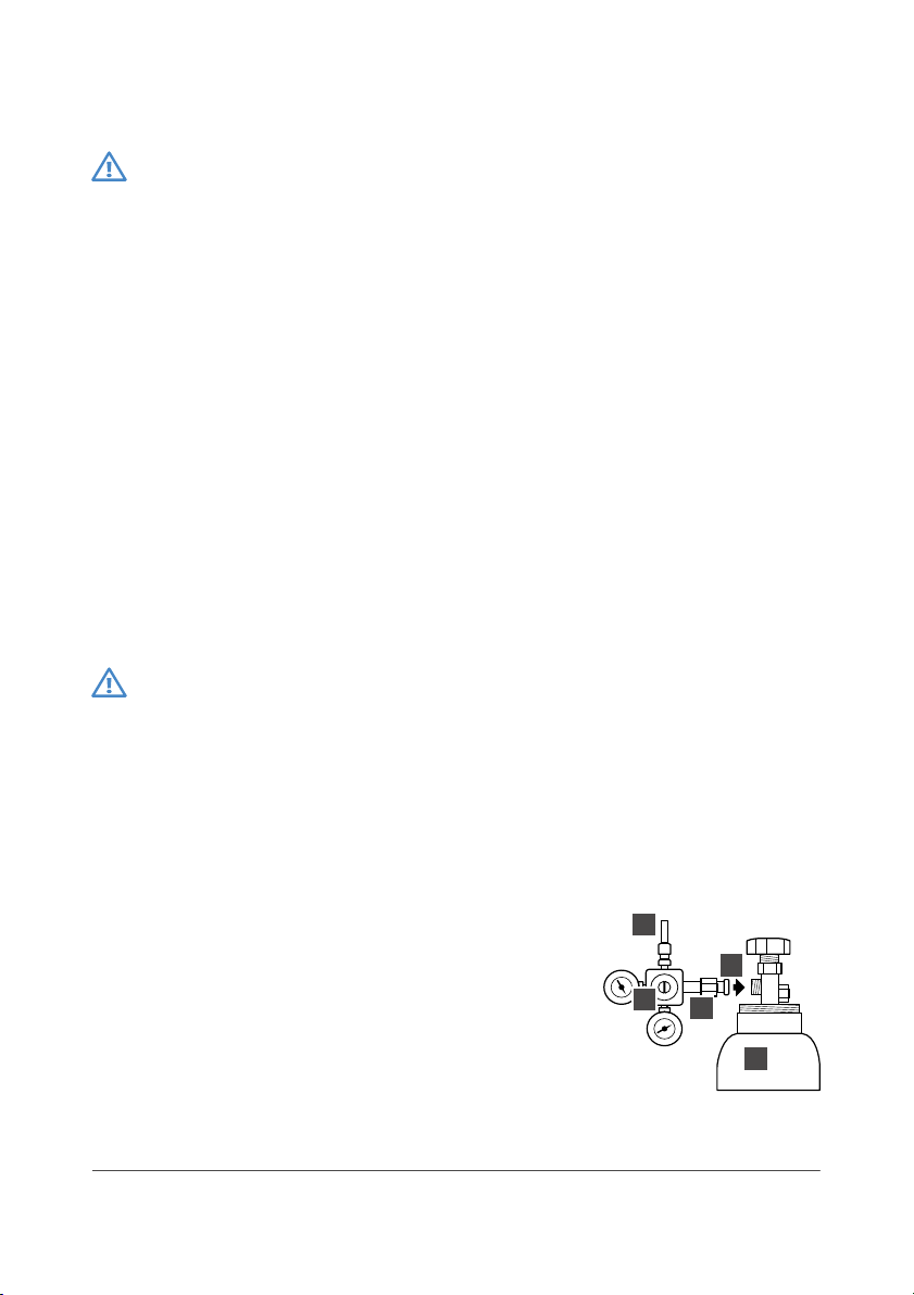
Connection with CO₂ cylinder
1. Connect the pressure regulator R with CO₂
cylinder B checking the correct position of
Teflon gasket.
2. Tighten the nut N and check that tubing T
(outlet) is connected properly
3. CO₂ cylinder must be kept in upright
position
4. CO₂ cylinder must be secured with a chain or
similar to avoid falling
14
T
RN
B
G
Before opening the CO₂ cylinder, follow the indications given in section
"Connection and duty start".
Regulation of CO₂ and temperature
Once the dispenser is on duty, it is necessary to regulate the level of
carbonation and the temperature.
CO₂ regulation
Sparkling water has two parameters for quality : the level of saturation
and the effervescence. The first is regulated with the pressure of co2, the
second depends on the type of watering entering into the dispenser and
the process of saturation. Regulation of co2 pressure must be set
between water supply pressure +0.5 bar with a maximum of 4 bar.
Important: the carbonation also depends on temperature. The
dissolution of co2, that is to say the level of carbonation, rises with the
lowering of water temperature. The final regulations has to be carried out
once the optimal working temperature has been reached (40/60
minutes from first start).
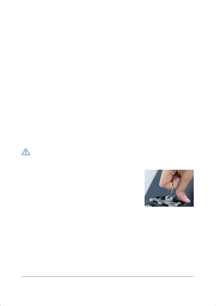
Warning air in the hydraulic system will hinder a good carbonation.
The presence of air bubbles can happen during first use.
These are the solutions:
1. Remove the upper part of the case and
discharge the carbonator: open the safety
valve pulling the specific ring.
2.Dispense a good quantity of sparkling water
at once until the dispenser will “blow”- the
pump cannot keep up with required
quantity of sparkling water and CO₂ will be
blown by aerator, expelling also air bubbles
Temperature regulation
The temperature of water supplied depends on inlet water temperature
and internal temperature of ice bank. The thermostat regulates the ice
bank and the temperature is already set. Regulating the thermostat to
higher temperatures we would have no ice, so the temperature can be
regulated while losing the thermal flywheel, that is to say lowering the
cool water supply capacity. The regulation of temperature can be done
15
through the thermostat placed inside the dispenser: the upper part of the
case has to be removed, then it is possible to set the specific black knob
“cooler” from 0 to 7- higher values mean cooler water.
Flow regulation
With a screwdriver the flow regulator placed at the rear of the dispenser
can be set as follows:
• Closing: lower flow and better carbonation
• Opening: higher flow and lower level of carbonation
1. Hermetic carbonator
2. Pump
3. Flow regulator
4. Condensator
5. Electronic board
6. Compressor
7. Vent
8. Evaporator
T. Thermostat
V. Solenoid valve
Management procedures for the dispenser
The dispenser could be equipped with 2 or 3 mechanical faucet,
depending on the type of water supplied. For water supply, simply full the
lever of the faucet towards you. The faucet for sparkling water is equipped
with a compensator to regulate the water flor and guarantee a good level
of carbonation.
In order to prevent malfunctioning of the pump, it is mandatory that the
dispenser runs water in its circuits. Is water supply is missing, a protection
system will stop the pump. The pump stops working after 4 minutes of
continuous work. To recover the functioning of the dispenser, please
unplug the dispenser from power supply and try again when water supply
is back.
12
5
4
6
8
7
T
V
3
16

Cleaning of draft faucet is essential to prevent water from bacteria
contamination. We suggest a daily cleaning with a non-toxic product
(hydrogen peroxide).
17

18
7. Maintenance
Regular maintenance
Cleaning of hydraulic system
End user can only carry out regular maintenance operations described in
following user guide, with the help of specialist if needed. The constructor
declines any liability if the procedures given are not being followed and
reserve it’s right to suspend the warranty.
Periodic cleaning is important to avoid bacteria growth. Especially when
the water supply is not covered by chlorine treatment, periodic
throughout cleaning is mandatory (at leat every 6 month)- or according to
water treatment systems installed before the dispenser.
Sanitization of hydraulic system must be carried out with a good oxidant
and solvent product, that efficiently removes silt and bacteria.
We suggest the use of hydrogen peroxide with a solution at 24 volumes,
and a maximum application time of 15 minutes. The use of other
disinfectant products, with strong oxidant power like peracetic acid or
ozone could lead to corrosions, vapors or noxious smell.
After the application of hydrogen peroxide, a good rinsing of hydraulic
circuits is necessary – at leat 5 liters for each circuit: ambient water, cold
water, sparkling water. The sparkling water systems, with its stock of
water, could need a longer rinsing. Litmus paper test can be used to check
if there is any hydrogen peroxide left..
Cooling system cleaning
The winglet of condenser for ventilation must be throughout cleaned by
aspiration or with a brush. Dust deposit will strongly reduce the
effectiveness of cooling system and irreparably damages the compressor
in the long term.
Warning any regular maintenance that need the intervention of
qualified professionals must be reported and described in the form at
the end of this manual “form II”.
Regular maintenance described is to be evaluated for a normal use of
the dispenser. In case of burdensome work amount of the machine,
the maintenance needs to be carried out more frequently
This manual suits for next models
2
Table of contents
Popular Water Dispenser manuals by other brands

BRIO
BRIO CLPOU320UVF4 Setup manual

Lancaster
Lancaster PLATINUM LINE LES X Factor Series Installation, operating and service manual

Osmio
Osmio Duo Hydrogen instruction manual

clage
clage Zip HydroTap G4 B 160 operating instructions

DOCRILUC
DOCRILUC ENFRIADOR-AGUA USER AND MANTINANCE MANUAL

Culligan
Culligan HD-202 Brochure & specs


