Waupaca Paca-Ryde User manual

Installation Instructions
Paca-Ryde
Elevator
Series 116
1,000 lbs.
PMI116-S
APRIL 2018
1726 North Ballard Road, Suite 1 • Appleton, WI 54911
Phone 920-991-9082 • Fax 920-991-9087
Technical Support 855-804-5774
www.waupacaelevator.com


1726 North Ballard Road, Suite 1 - Appleton, WI 54911 - 920.991.9082
Technical Support 855.804.5774 - Parts@waupacaelevator.com
W
E
PMI116- TC-S
02 APR 2018
Installation Table of Contents
General Information Series 116
Description.................................................................... Page
General Information.......................................... ....................................4
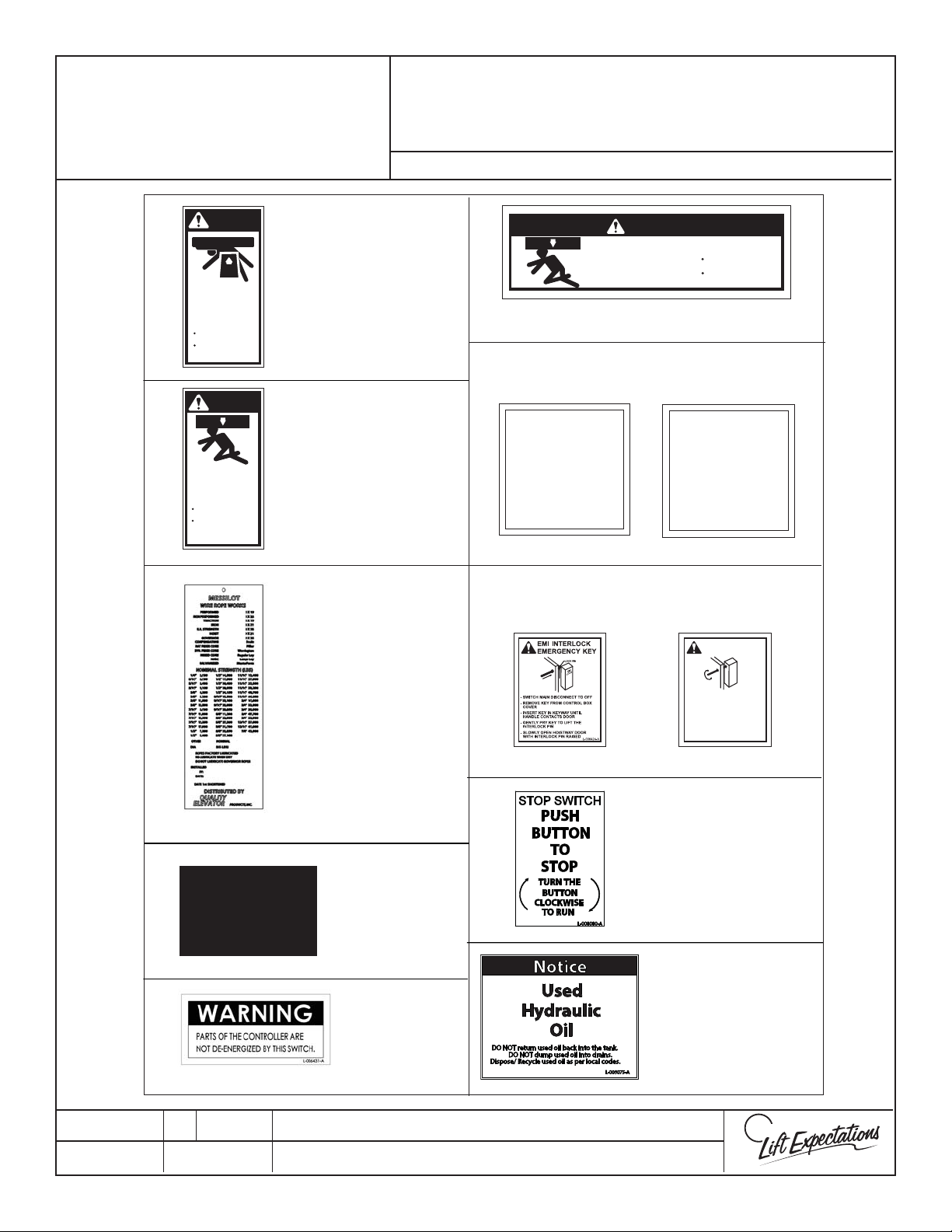
Warning and Safety Label Install.................................. ....................5
Factory Installed Warning & Safety Label Installation...................6
Hyrdaulic Elevator Recommended Tool List................................. 7
Return Material Authorization....................... ....................................8
Troubleshooting with Tech Support............ ....................................9
Hoistway Dimensions ....................................... ..................................10
Rail and Pedestal Installation ........................ ..................................11
Two Piece Jack Assembly................................. ..................................12
Jack Installation................................................... ..................................13
Ram Header Installation .................................. ..................................14
Controller Installation and Wiring ............... ............................15-16
GMV/OLS Hydraulic Power Unit Installation ............................. 17
Final Limit Installation .......................................................................18
Pendant Control.................................................. .................................19
Pisten Projection................................................. .................................20
Proper Wiring Rope Handling ....................... .................................21
Wire rope & Shackle Installation ................... ..........................22
Sling & Side Extension Installation..........................................23
Sling Assembly and Safety Installation..................................24-26
Stabilizer Bracket Adjustment & Sling Extension Installation..... 27
Verify Jack travel.......................................................................... ........ 28
Car Operating Panel Installation.................................................... 29
Wall Mount Telephone Jack............................................................. 30
Handrail Installation .......................................... .................................31
Framless Car Assembly ...............................................................32-34
Stabilizer Bracket Installation ........................ ...............................35
Steel Tape and Tape Reader Installation ... .................................36
Description............................................. ..........................Page
Modular Wiring Car Top Layout .................... ..................................37
Car Top Modular Wiring...........................................................................38
Tape Reader Interface Board Connections . ..............................39
LED Light Installation........................................................... ..............40
LED Light Wiring (without battery backup wiring)..............41
LED Light Wiring (without battery backup wiring)...........42
Accordion Gate Installation...........................................................43-44
Frameless Car Gate Switch .......................................................................46
Travel Cable Installation................................... ..................................47
Travel Cable to Controller Wiring........................................................48
Hoistway Wiring Layout ................................... ...................................49
Hall Station Wiring & Installation.........................................................50
Stop Pit Switch Installation................................................................51
EMI & GAL Magnet Placement 6 Stop...............................................5 2
Toe Guard Installation....................................... ....................................53
Automatic Operation........................................ ....................................54
GMV/OLS Microprocessor Inputs and Outputs.............................55
Programs & POT Settings................................................................56-57
Auto Gate Program............................................ ....................................58
Emergency Light Installation and Fuse Installation.....................59
Valve Adjustments ............................................. ..............................60-62
Troubleshooting ................................................. ...............................63- 64
Troubleshooting PLC Inputs and Outputs. .............................65-66
Troubleshooting Controller Layout.................................................67
Excelevator Semi- Annual General Maintence Chart...................68
Excelevator Semi- Annual Maintence Messages........................69
Elevator Release Checklist............................... ..................................70

1726 North Ballard Road - Appleton, WI 54911 - 920.991.9082
Technical Support 800.238.8739 - TechSupport@WaupacaElevator.com
PM0010-B
/18/2011
CRUSH
HAZARD
CUTTING
HAZARD
CRUSH
HAZARD
CRUSH
HAZARD
CRUSH
HAZARD
CRUSH
HAZARD
ECO-SYSTEM
HAZARD
ELECTRIC
HAZARD
FALLING
HAZARD
INHALATION
HAZARD
CRUSH
HAZARD
KINK
HAZARD
MISSILE
HAZARD
CRUSH
HAZARD
PINCH
HAZARD
PROJECTILE
HAZARD
PUNCTURE
HAZARD
ANTI-
STATIC
ALERT
STATIC
HAZARD
ELECTRICITY
For purposes of visual clarication, some parts have been
omitted from certain illustrations.
Illustrations are of typical parts and may not match your
materials exactly.
Illustration Notication
Waupaca Elevator Company subscribes to the ACCESSIBILITY EQUIPMENT MANUFACTURERS ASSOCIATION
(AEMA) Code of Ethical Practices:
Be it resolved that we will conduct our business aairs in such a manner that they will be fair to all parties concerned.
Ethical Standards
Danger!
Indicates a condition where failure to follow
exact instructions or heed warnings may result
in equipment damage, personal injury or death.
Safety Alerts
Introduction
These symbols will remind you of potential injury.
Important
Indicates critical information that should be
reviewed carefully.
General Reminders
This manual is designed as a guide to the installation
and maintenance of this Waupaca Elevator unit. The
instructions are designed to help ensure the safe
installation and operation of this unit. Read them
carefully before beginning installation.
Inspect for visible signs of damage or missing parts
BEFORE beginning installation. The nal check list
indicates all components included with this order.
Work by others to include, but not limited to, the
hoistway construction, supports for guide rails and an
electrical fused disconnect to control panel.
Do not expose electrical components to the elements or
extreme temperature uctuations. Resulting condensa-
tion will damage equipment, causing it to malfunction. If
exposed, let sit for 12-24 hours prior to operation.
Safe operation requires a maintained hoistway
and mechanical room temperature between 60° F
to 110° F.
• And further resolved, that we will manufacture and/or distrib-
ute only products which reect good quality, safety and the
best engineering practices for any given application.
• And further resolved, that we will respect our competitors
deserving of our respect.
• And further resolved, that we will refrain from being deroga-
tory.
• And further resolved, that we will not take unfair advantage of
our dealers.
• And further resolved, that we will always uphold the high
standards and the purposes of AEMA.
• And further resolved, that we will refuse to be party to
any of the following: price xing, collusion monopoly,
non-code compliance, deviation from specications after
quoting, and knowingly endorsing members of this or
any other trade association if they are not qualied or are
known to be unethical or dishonest.
Installation should be done by a trained authorized
Elevator Contractor in accordance with these
instructions and in compliance with requirements
of National Elevator Code, National Electrical Code,
American Standard Safety Code, and State and
Local Building Codes.
GENERAL INFORMATION
W
E
Page 4

PTS70014-J
29 MAR 2018
W
E
SERIES : 114 ,116
1726 North Ballard Road, Suite 1 - Appleton, WI 54911 - 920.991.9082
Technical Support 855.804.5774 - Parts@waupacaelevator.com
Wire Rope Tag
(1) To the wire
rope where it
will not interfere
with elevator
operations.
(Tag may vary
due to supplier.)
GAL INTERLOCK
EMERGENCY KEY
- SWITCH MAIN DISCONNECT TO "OFF"
- SLOWLY OPEN HOISTWAY DOOR WITH
INTERLOCK RELEASED
- GENTLY TURN KEY TO RELEASE
INTERLOCK
- INSERT KEY IN KEYWAY UNTILHANDLE
CONTACTS INTERLOCK
- REMOVE KEY FROM CONTROL BOX
COVER
L-006427-A
GAL
LOCK
DANGER
L-006435-A
Elevator car can
come up and crush
you to death!
Before entering this area:
Pull Emergency Stop
Use a 4 foot brace on
top of car
DANGER
L-006381-A
Elevator car can
come down and
crush you to death!
Before entering this area:
Pull Emergency Stop
Use a 4 foot brace to
support car
(1) To front
wall in the
overhead of
hoistway.
(1) On top of
elevator car.
(1) To hoistway
wall 3’above
pit facing door.
(1) On the Jack
(1-3) Center in opening/s on toe guard
(1) To controller face next to
emergency key holding bracket.
(EMI interlock)
NON-LOAD
BEARING
SURFACE
L-007722-A
(2) Place label on the
ceiling exterior of
the elevator car.
Label must be visible
from opening
DANGER
L-006428-A
Elevator car can
come down and
crush you to death!
Before entering this area:
Pull Emergency Stop
Use a 4 foot brace to
support car
(1) To the inside of cab
(manual gate only) (1) To the inside of cab
(automatic gate only)
(GAL interlock)
or
(2) Placed on the
disconnects
110V & 240V
OPERATING INSTRUCTIONS
FOR WAUPACA ELEVATORWITH MANUAL GATE
IF ELEVATOR STOPS BETWEEN FLOORSWAIT 7 SECONDS AND TRYTO
RETURN TO FLOORTHAT YOU CAME FROM, IF YOU REMAIN STUCK PRESS
ALARM BUTTON TO GET ASSISTANCE IN THE HOUSE OR USE PHONE TO
GET ASSISTANCE.
DO NOT ATTEMPT TO REPAIRTHIS ELEVATORYOURSELF.
CALL DEALER FOR SERVICE OR AN ELEVATOR SERVING COMPANY
DO NOT REMOVE OR COVERTHIS SIGN. L-006432-B
1. Close hoistway door and close elevator gate.
2. If keylock is provided, insert key in lock and turn to “ON”.
3. Press desired oor on the car operating panel.
4. Once stopped at landing open gate.
5. Open door and exit elevator.
6. Close the gate.
7. Securely close hoistway door.
8. Should elevator fail to operate.
-Verify gate and hoistway door are fully closed.
-If keylock equipped, verify key is in the “ON” position
-Verify that the emergency stop button is pushed in.
9. Do not load elevator beyond its rated capacity.
10. Do not open gate while elevator is in motion.
11. Keep all body parts inside the elevator car at all times.
OPERATING INSTRUCTIONS
FOR WAUPACA ELEVATORWITH AUTOMATIC GATE
IF ELEVATOR STOPS BETWEEN FLOORSWAIT 7 SECONDS AND TRYTO
RETURN TO FLOOR THAT YOU CAME FROM, IFYOU REMAIN STUCK PRESS
ALARM BUTTON TO GET ASSISTANCE IN THE HOUSE OR USE PHONE TO
GET ASSISTANCE.
DO NOT ATTEMPT TO REPAIRTHIS ELEVATORYOURSELF.
CALL DEALER FOR SERVICE OR ELEVATOR SERVICING COMPANY
DO NOT REMOVE OR COVERTHIS SIGN. L-006434-B
1. Close hoistway door and the elevator gate will automatically close.
2. If keylock is provided, insert key in lock and turn to “ON”.
3. Press desired oor on the car operating panel.
4. Once stopped at landing the gate will automatically open.
5. Open door and exit elevator.
6. Securely close hoistway door.
7. Should elevator fail to operate:
- Verify gate and hoistway door are fully closed.
- If keylock equipped, verify key is in the “ON” position.
- Verify that the emergency stop button is pushed in.
8. Do not load elevator beyond its rated capacity.
9. Do not open gate while elevator is in motion.
10. Keep all body parts inside the elevator car at all times.
(1-3) Place label right next
to the pit stop switch in
the hoistway pit
(1) Place the label
facing toward the
hoistway shaft on the
plastic container that
catches the oil in the
hoistway.
WARNING & SAFETY
LABEL INSTALLATION
Page 5

PTS70014-J
29 MAR 2018
W
E
SERIES : 114 ,116
1726 North Ballard Road, Suite 1 - Appleton, WI 54911 - 920.991.9082
Technical Support 855.804.5774 - Parts@waupacaelevator.com
WARNING
For Continued Protection Against Risk of Fire,
Replace with same Type and Rating of Fuse.
AMP, Time Delay
L-006383-A
L-006405-A
FUSE VALUE TYPE
IN OR ON CONTROLLER ALARM BELL &
CONTROLLER
WARNING
L-006392-A
Hazardous voltage
can shock, burn or
cause death.
Do not enter or
service yourself.
Call a qualied repairman.
Electrostatic sensitive devices within.
Observe anti-static precautions.
L-006394-A
ALARM BELL &
TAPE READER
WARNING
GATE SWITCH BYPASS
AND/OR GATE REMOVAL
IS PROHIBITED BY CODE.
SERIOUS INJURY OR
DEATH COULD RESULT.
L-006416-A
GATE
WARNING : MORE THAN ONE LIVE CIRCUIT.
SEE DIAGRAM.
AVERTISSEMENT . CET ÉQUIPEMENT
RENFERME PLUSIEURS CIRCUITS SOUS
TENSION. VOIR LE SCHÉMA.
Overload protection is 150 % of full load current ( Fuse on board)
T
his unit does not incorporate overspeed protection
Screw Drive
Gate Operator
120V, 3A, 60Hz
ASME A17.5
CAN/CSA B44.1
File: 100104201CHI-001
L-006469-A
ASME A17.5
CAN/CSA B44.1
File: 100104201CHI-001
WARNING : MORE THAN ONE LIVE CIRCUIT.
SEE DIAGRAM.
AVERTISSEMENT . CET ÉQUIPEMENT
RENFERME PLUSIEURS CIRCUITS SOUS
TENSION. VOIR LE SCHÉMA.
Overload protection is 150 % of full load current (
Fuse on board)
T
his unit does not incorporate overspeed protection
Belt Drive
Gate Operator
120V, 3A, 60Hz
L-006470-A
CARTOP
SCREW DRIVE
GATE OPERATOR
BELT DRIVE
GATE OPERATOR
EMI III AC & DC
L-006700-A
Waupaca Elevator Company
100291858CHI-001
COMPLIES WITH UL STD104,
ASME-A17.1, AND CSA B44.
MODEL: EMI IV
VOLTAGE: 24 VDC, 2A
24 VAC,2A
CERTIFIED OCTOBER 2011
"FOR RESIDENTIAL USE ONLY"
Intertek
EMI IV AC & DC
Elevator car can come
down and can cause
SEVERE INJURY or DEATH
Before disconnecting hose:
• Secure car and sling
Do not attempt to replace this hose
Installed by:
______________________________
Date Installed:
______________________________
PER ASME A17.1: REPLACE HOSE EVERY 6 YEARS OR
SOONER IF REQUIRED BY LOCAL JURISDICTION
L-006430-B
Minimum Bend Radius: 4.80 in.
Factory Test Pressure: 3700 PSI
Factory Test Date: _______________
Inspection of hose to occur annually, or as
directed by local jurisdiction
Visual Inspection:
Check for weeping, leakage, kinks, twists, crushed
sections, or damage to outer covering
Pressure Test:
Run unit upward until stop ring is engaged and
pressure relief valve activates. Continue to run
pump for 30 seconds while checking for:
• Leakage
• Slippage of Fittings
• Exposure of Inner Reinforcement
• Bulging/Distortions of Hose Body
High pressure hydraulic
lines, keep hands clear
while pressure testing
L-006430-B
COMPANY: TECHNICIAN: DATE:
Voltage (V): Freq. (Hz): Phase (Ø): Wiring Diagram #:HP: Current (A):
Serial #:
Enclosure Type: UL File: Plant Location:
Short Circuit Current: KA rms symmetrical at V maximum
L-006385-B
DANGER - HIGH VOLTAGE
CAUTION:
Read and understand. Risk of electric shock. To reduce the risk of fire,
replace fuse with same type and rating. More than one disconnect may be used. De-energize
prior to servicing or adjusting. Indoor use only.
EMI AC & DC
WARNING
INTERLOCK BYPASS
AND/OR REMOVAL IS
PROHIBITED BY CODE.
SERIOUS INJURY OR
DEATH COULD RESULT.
L-006380-A
POWER UNIT
CARTOP
WAUPACA ELEVATOR INC.
"As to electrical, shock and re hazard, and in accordance with
ASME A17.5-2014 and CAN / CSA B44.1-2014"
E180739
ENCLOSED ELEVATOR CONTROL PANEL
XXXXXX
L-006406-C
WARNING : MORE THAN ONE LIVE CIRCUIT.
SEE DIAGRAM.
AVERTISSEMENT . CET ÉQUIPEMENT
RENFERME PLUSIEURS CIRCUITS SOUS
TENSION. VOIR LE SCHÉMA.
Copper conductors only!
4000929
Waupaca Elevator
Cartop Box
Elevator
120V, 10a, 60Hz
CONFORMS TO ASME STD A17.5
CERTIFIED TO CAN/CSA STD B44.1
File: 102879262CHI-00
1
L-007881
CAUTION
NO LIFT - NO STEP
L-006413-A
CARTOP
CAPACITY TAG
®
HYDRAULIC HOSE BUFFER SPRING TAGS
(1) PER BUFFER SPRING
MAY VARY
FACTORY INSTALLED
WARNING & SAFETY
LABEL INSTALLATION
Page 6

1726 North Ballard Road, Suite 1 - Appleton, WI 54911 - 920.991.9082
Technical Support 855.804.5774 - Parts@waupacaelevator.com
PTS70018-C
29 MAR 2018
W
E
Measuring Tools
□2’Level
□4’Level
□6’Level
□Laser Level
□25’Tape Measure
□Chalk Line
□Framing Square
□Plumb Line
□Calipers
SERIES : 114, 116
HYDRAULIC ELEVATOR
RECOMMENDED TOOL
LIST
Safety Equipment
□Hard Hat
□Safety Glasses
□Steel Toe Boots
□Heavy Gloves
□Fall Protection Equipment
Power Tools
□3/8”Cordless Drill & Drill Bits
□1/2”Hammer Drill & Drill Bits
□Shop Vac
□Extension Power Cord
□Reciprocating Saw (Sawzall)
Miscellaneous Equipment & Supplies
□Ladder and Planks
□Material to Close O Hoistway
□Chain Hoist
□All Purpose Grease
□Wood Glue
□Paran Wax
□Temporary Supports for car
□Thread Locker
□Rags or Toweling
Hand Tools
□Socket & Wrench Set
□Allen Wrenches SAE & Metric
□Utility Knife
□Cable Cutter
□File Set
□Flashlight
□Needlenose Pliers
□Rubber Mallet
□Hack Saw
□Scissors
□Set of Screw Drivers (at & Phillips)
□Vise Grips
□Wall Board Roll Lifter
□Pre-set Interchangeable Head Torque
Wrench Box End Style & Socket Style
(up to 125 ft. lbs. plus)
□Clamps
□Spanner Wrench (142 mm, Pin Dia. 8mm)
□Torque Wrench/Screw Driver
Electrical Wiring Tools & Supplies
□Wire Crimper
□Wire Marker Tape
□Wire Stripper
□Multi-Meter
□Clamp on Ammeter
□Appropriate Fuses
(see controller schematic)
□WEC Pendant
Hydraulic Equipment & Supplies
□Mineral Spirits
□Hydraulic Oil
□PTFE Thread Tape
□PTFE Thread Paste
Page 7

1726 North Ballard Road, Suite 1 - Appleton, WI 54911 - 920.991.9082
Technical Support 855.804.5774 - Parts@waupacaelevator.com
PTS70004-E W
E
09 OCT 2017
SERIES : ALL
1. An RMA Number must be issued at the time the part is ordered, not after the fact, for all CREDIT and
WARRANTY parts returns.
2. When placing an RMA order, specic information will be required as follows:
a) UNIT’S SERIAL NUMBER
b) part number (if available)
c) exact description of the problem
d) date of manufacture
Have this information ready when you call to expedite the process!
3. All returns must be clearly marked with the assigned RMA number on the outside of the container.
4. No item will be accepted without an RMA number.
5. Outbound Material RMA will be sent out UPS/FEDEX Ground.
6. Any additional shipping costs will be at the dealer’s expense.
7. Absolutely no returns will be accepted after 45 days. All RMA’s have a 45-day open date for receipt by
Waupaca Elevator.
8. All replacement part orders will be invoiced upon shipping and will not be credited until the original
part(s) have been returned to the factory prepaid (no C.O.D.’s will be accepted).
a) Credit will be issued if evaluation proves components or to have failed within our
warranty period.
b) Credit will not be issued if the parts have been installed improperly or misused.
8. Any electrical items returned in proper working condition will be returned to the dealer at the dealer’s expense.
9. Waupaca Elevator reserves the right to deny credit.
10. Some parts may be subject to a 20% restock fee.
11. ALL PARTS HAVE A 90 DAY WARRANTY.
12. We encourage your cooperation with this policy as it will further expedite warranty replacement, better track
returns and allow us to adjust your account in a timely and accurate manner.
To Contact Waupaca Elevator Technical Support
Please Call: 855-804-5774
or
E-mail: Parts@waupacaelevator.com
RETURN MATERIAL
AUTHORIZATION
PROGRAM - RMA
Page 8

1726 North Ballard Road, Suite 1 - Appleton, WI 54911 - 920.991.9082
Technical Support 855.804.5774 - Parts@waupacaelevator.com
PTS70009-E W
E
Series: ALL
31 JULY 2017
Must Have
1. Serial Number of the unit
2. Multimeter
3. Wire Stripper
4. 1/8”Flat Screwdriver
5. Flashlight
6. Wiring Diagram for the unit
Other Suggested Items
1. WEC Pendant
2. Note pad
3. Writing Utensil
4. Fuses
5. Socket set SAE and Metric
6. Wrench Set SAE and Metric
7. Allen Wrenches SAE and Metric
8. Clamp on Ammeter
9. Rags and Oil Dry
Troubleshooting Tips
1. Take notes as you troubleshoot for future reference.
2. Visually inspect component(s).
3. Check for loose wires and broken contacts.
4. Be familiar with your multimeter.
5. When testing fuses take them out of the circuit (failure to do so may result in a false reading).
6. When checking for voltage do not check to ground
For Technical Support Call : 1-855-804-5774
CRUSH
HAZARD
CUTTING
HAZARD
CRUSH
HAZARD
CRUSH
HAZARD
ECO-SYSTEM
HAZARD
ELECTRIC
HAZARD
FALLING
HAZARD
INHALATION
HAZARD
CRUSH
HAZARD
KINK
HAZARD
CRUSH
HAZARD
PINCH
HAZARD
STATIC
HAZARD
ELECTRICITY
Having the following items on hand will make the troubleshooting
process easier and quicker.
TROUBLESHOOTING WITH
TECHNICAL SUPPORT
Page 9

1726 North Ballard Road, Suite 1 - Appleton, WI 54911 - 920.991.9082
Technical Support 855.804.5774 - Parts@waupacaelevator.com
W
E
PTM30008-B
MARCH 2009
Hoistway Dimensions
Hoistway must be plumb, square and have no
dimension greater than 1”or less than 1/2” as
compared to the hoistway layout drawings.
Verify the following with your eld drawings:
Hoistway dimensions
Total travel
Pit depth
Clear overhead
Doorways are In-Line
Rail Backing
Chain hoist attachment point
(Strongly Recommended)
Hoistway Dimensions
FAILURE TO VERIFY
these dimensions with
the drawings on site, may
drastically INCREASE the
amount of TIME spent on
the job!
Other Hoistway Verications
Verify these other hoistway dimensions
and specifications before proceeding with
installation of elevator.
1
2
3
4
5
A-Machine room location &
dimensions (if applicable)
B- Clear access to hoistway
6
7
Note: The use of a laser level is recommended for verifying
the hoistway dimensions and for locating and
marking the center line during rail bracket installation.
SERIES: ALL
Page 10

1726 North Ballard Road, Suite 1 - Appleton, WI 54911 - 920.991.9082
Technical Support 855.804.5774 - Parts@waupacaelevator.com
PTM30130-E
13 MAR 2018
W
E
CRUSH
HAZARD
CUTTING
HAZARD
CRUSH
HAZARD
CRUSH
HAZARD
FALLING
HAZARD
CRUSH
HAZARD
PINCH
HAZARD
ASSEMBLE MAIN RAIL PER FIELD DRAWINGS
PEDESTAL
BASE
PEDESTAL
RAIL PIN
21" +/- 1/32"
MEASURE DISTANCE
& DIVIDE BY 2
A
D
MOUNTING
BOLTS
RAIL SECTION
LEVEL
LEVEL
2.
3.
4.
11.
1.
5.
7.
6.
8.
9.
10.
12.
13.
14.
VERIFY ALL FASTENERS ARE SECURELY FASTENED
2, 3
5
7
14
4
3
3
RAIL AND PEDESTAL
INSTALLATION
SERIES : 116
Use eld drawings to determine where to center the rail on the
hoistway wall and mark a centerline.
Mark plumb line 16 5/8” over to the left or right of the
centerline.
Distance Between Guides (DBG) should be 21” apart inside
to inside. Measure corner to corner on each section of rail
to determine if rail section is square. Loosen mounting bolts
and adjustment as necessary to ensure rail section is square.
Torque 1/2” rail fasteners to 85 ft. lbs. Verify the rail ends are
not oset at the top and bottom of each rail section.
Set pedestal base into place on the pit oor.
Align rst section of rail with plumb line in the hoistway. Drill
(2) appropriately sized pilot holes centered in each slot per rail
bracket. Loosely fasten with architect specied hardware.
To allow for the next rail section to be installed, loosen rail clip
bolts.
Insert rail pins into predrilled holes on the top installed rail
section. Align rail with the predrilled holes on the bottom of the
next rail section and carefully lower into place.
Drill (2) appropriately sized pilot holes centered in each slot per
rail bracket. Loosely fasten into place with architect specied
hardware. Finish fastening rail clips from step 6. Verify rail is
plumb and level. Torque rail clip hardware bolts to 85 ft-lbs.
Continue rail installation following the steps 6 & 7 until the rail
is completely installed.
Verify the rail install is complete and plumb. Adjust and shim if
needed. Securely fasten rail to rail backing.
Refer to eld drawings for pedestal and jack locations and
install both brackets in appropriate locations using a plumb line
and loosely fasten with architect specied hardware.
Align jack and pedestal brackets with rail brackets. Shim as
required to match rail brackets and securely fasten hardware.
Set pedestal into pedestal base.
Hand tighten pedestal to pedestal bracket with the
following provided hardware:
(2) - 3/8”-16 x 4-1/2”Bolts (1) - Clamping Plate
(4) - 3/8”Flat Washers (2) - 3/8”Lock Washers
(2) - 3/8”-16 Nuts
Plumb pedestal and securely fasten.
Note: Do not over tighten, or the plate may bend and
interfere with the sling.
Page 11

1726 North Ballard Road, Suite 1 - Appleton, WI 54911 - 920.991.9082
Technical Support 855.804.5774 - Parts@waupacaelevator.com
PTM30061-C
1/21/2013
W
E
CRUSH
HAZARD
CUTTING
HAZARD
CRUSH
HAZARD
CRUSH
HAZARD
FALLING
HAZARD
CRUSH
HAZARD
PINCH
HAZARD
PUNCTURE
HAZARD
ECO-SYSTEM
HAZARD
Step 1Disassemble jack parts (leave bottom piston in bottom
sleeve) and bring into hoistway. Use a spanner wrench (142mm,
pin diameter 8mm) for this step. Use bell hoist for chain
hoisting parts into place. Clean all threads with a non-residual
solvent. Wood“V” blocks may help for maintaining jack position
while assembling.
Step 2Set bottom assembly onto jack cup (refer to jack installation).
Step 3 Place O-ring between pistons. Do not crossthread! Thread top
piston & bottom piston together with provided thread locker until
painted lines match.
Step 4 Plumb and polish joint. Check for clear and smooth surface
between pistons.
Step 5 Fit O-ring onto bottom of top sleeve.
Step 6 Using provided thread locker, thread top sleeve into bottom
sleeve. Use a spanner wrench (142mm, pin diameter 8mm) for
this step. Refer to jack installation for PRV positioning. Remember,
DO NOT CROSSTHREAD!
Step 7 Fasten top sleeve to jack bracket. If a second jack bracket is
provided, fasten to bottom sleeve (reference eld drawings for
bracket locations.
Step 8 Insert gland assembly into top sleeve.
Step 9Fasten ange assembly to top sleeve with socket head cap screws.
Refer to jack installation for overow relief positioning.
Step 10 WAIT 24 HOURS BEFORE FILLING WITH OIL.
WARNING
DO NOT DISASSEMBLE THESE TWO ASSEMBLIES.
IF SEAL IS BROKEN, THE PARTS WILL NEED TO BE REPLACED.
ATTENTION
Make sure that all pistons, cylinder and components are kept from
damage, loss or contamination.
While threading be careful not to damage and/or scar the inside of top sleeve.
Return to Jack Installation Instructions
Carefully examine piston for damages, scratches, score marks or nicks.
The damage must be removed prior to changing or assembling seals,
using a 12” smooth at le, 180 and 240 grit emery cloth. Bad damage
can be removed using le on a 45° angle to the center line of piston,
nish the surface with 240 grit emery cloth.
BELL HOIST
FLANGE
O - RING
WIPER SEAL
MAIN SEAL
(TEXTURED
SIDE UP)
GLAND
TOP SLEEVE
O - RING
TOP PISTON
COLLAR
BOTTOM PISTON
BOTTOM SLEEVE
O - RING
BOLT
SERIES 114 - 116
TWO PIECE
JACK ASSEMBLY
Page 12

1. Set jack cup onto pedestal.
2. Verify that socket head cap screw is installed in
bottom of jack. Set jack onto jack cup by inserting head
of screw into jack cup alignment hole.
3. Loosely fasten jack to jack brackets with U-bolt, rubber
strap and provided hardware. (Trim the rubber strap if
necessary)
Note: Do not double up the rubber strap and
be sure to have the gap in the front of the jack.
4. Remove the plate from jack inlet port and mount Pipe
Rupture Valve (PRV) to jack with provided O-ring,
screws and washers.
Note: Lubricate O-ring with hydraulic oil. The O-ring
and mating surfaces must be clean.
5. Attach hydraulic pipe from PRV to tank.
Note: The inside of the pipe and attaching threads
must be clean. All hydraulic piping must meet
ASME 17.1/CSA B44 and local codes.
6. Rotate PRV as needed to maintain mechanical
clearances.
7. Plumb and securely fasten jack to jack brackets by
tightening U-bolt.
Note: Compress rubber strap approx. 1/8”do not
over tighten.
8. Screw tube tting into weep hole on the jack crown
overow relief with elbow facing downward direction.
9. Press tube over tube tting rmly until tube is fully
secure, run down jack, and into drip jug (do not
obstruct any part of the elevator) and secure tube to
jack.
1726 North Ballard Road, Suite 1 - Appleton, WI 54911 - 920.991.9082
Technical Support 855.804.5774 - Parts@waupacaelevator.com
PTM30173-B
29 MAR 2018
W
E
JACK INSTALLATION
Series: 114, 116
Use a laser level to verify rail system, pedestal and jack are all
plumb and properly aligned. If the jack and rail system are not
properly installed this may cause premature seal failure, abra-
sive wearing, leaks and noise throughout the elevator system.
1.
2.
3.
4.
5.
6.
7.
8.
9.
1
2
3
4
5
6
7
8
9
Note: Contaminated oil will cause valve problems and more intensive maintenance.
SERIES 114 SHOWN FOR
ILLUSTRATIVE PURPOSES JACK CUP
Page 13

1726 North Ballard Road, Suite 1 - Appleton, WI 54911 - 920.991.9082
Technical Support 855.804.5774 - Parts@waupacaelevator.com
PTM30138-C
21 MAR 2018
W
E
CRUSH
HAZARD
CUTTING
HAZARD
CRUSH
HAZARD
CRUSH
HAZARD
FALLING
HAZARD
CRUSH
HAZARD
KINK
HAZARD
CRUSH
HAZARD
PINCH
HAZARD
GUIDE
BLOCK
GUIDE
BLOCK
ARM
RAM
HEADER
JACK
MOUNTING
BRACKET
1.
2.
12
4
10.
4.
3.
5.
6.
7.
8.
9.
RAM HEADER
INSTALLATION
SERIES : 116
Remove jack mounting bracket from ram
header by removing the following:
(4) 1/2” lock washer
(4) 1/2”-13 x 1 machine screw
Remove bolt from top of jack and fasten
the jack mounting bracket to the jack with
the previously removed bolt.
(M30 x 3.5 bolt x 70mm bolt)
Verify jack bolt is secure.
Remove a guide block arm from ram
header by removing the following:
(2) 1/4-20 machine screw
(2) 1/4”lock washer
(2) 1/4”at washer
Loosen opposite side.
Press guide blocks into position on the guide block arms. Be sure to adjust
the orientation of the guide blocks so the thickest part of the block is to the
rail wall.
Place ram header on jack mounting bracket with the previously removed
hardware:
(4) 1/2” lock washer
(4) 1/2”-13 x 1 machine screw
Torque the 1/2” fasteners to 78 foot lbs.
Reattach the previously removed guide block arm and block.
(2) 1/4-20 machine screw (2) 1/4”lock washer
(2) 1/4”at washer
Securely fasten hardware while creating a snug t between the rails.
Verify ram header is plumb.
Securely attach the wire rope tag.
Page 14

PTE10056-I
09 MAR 2018
W
E
1726 North Ballard Road, Suite 1 - Appleton, WI 54911 - 920.991.9082
Technical Support 855.804.5774 - Parts@waupacaelevator.com
CRUSH
HAZARD
CUTTING
HAZARD
CRUSH
HAZARD
CRUSH
HAZARD
ELECTRIC
HAZARD
FALLING
HAZARD
CRUSH
HAZARD
PINCH
HAZARD
STATIC
HAZARD
ELECTRICITY
• Locate controller enclosure in the machine room as required by code.
• Wire gauge requirements:
10 gauge wire for power to motor
14 gauge for solenoid coils
18 for all low voltage
• Refer to unit specic schematics in eld drawings to complete wiring.
Wire per N.E.C. and local codes.
Note: Not all controller terminals or travel cable wire may be used. High voltage and low
voltage wire must run separate and only cross over perpendicular to each other.
• Locate and check for correct fuse sizes.
Disconnect Power Before Wiring
1
1
0
V
2
3
0
V
36” from the face of
the equipment
The height of working
space in front of
equipment must be a
minimum of 6-1/2 ft. or
height of the equipment,
whichever is greater per
NEC Code
30” minimum width or
the width of the equipment
Per NEC Code 110.26 .......
Clear Working Space. The working space
required by this section must be clear at all
times. Therefore, this space isn’t permitted
for storage. When normally enclosed live
parts are exposed for inspection or servicing,
the working space, if in a passageway or
general open space, must be suitably
guarded.
Working Space. Equipment that may need
examination, adjustment, servicing, or
maintenance while energized must have
working space provided in accordance
with(1), (2), and (3):
1. Depth of Working Space. The working
space, which is measured from the
enclosure front, must not be less than the
distance of 36”.
2. Width of Working Space. The width of the
working space must be a minimum of 30”,
but in no case less than the width of the
equipment.
CONTROLLER
INSTALLATION AND
WIRING SERIES : 114, 116
Page 15

PTE10056-I
09 MAR 2018
W
E
1726 North Ballard Road, Suite 1 - Appleton, WI 54911 - 920.991.9082
Technical Support 855.804.5774 - Parts@waupacaelevator.com
Build out
Disconnect
110V
Controller Size
Standard
24-1/2”x 18-5/8”x 8”
14-1/2 in
Note: The machine room may be placed on any oor of on any
level of the home
Disconnect/
Light Switch
230V
Overhead View
30 in
36 in of the face of
the equipment
CRUSH
HAZARD
CUTTING
HAZARD
CRUSH
HAZARD
CRUSH
HAZARD
ELECTRIC
HAZARD
FALLING
HAZARD
CRUSH
HAZARD
PINCH
HAZARD
STATIC
HAZARD
ELECTRICITY
CONTROLLER
INSTALLATION AND
WIRING SERIES : 114, 116
Per NEC Code 110.26 Continued .......
3. Height of Working Space (Headroom). The height of the working space in front of equipment must
not be less than 6½’ measured from the grade, oor, platform, or the equipment height, whichever is
greater.
Other equipment must not extend more than 6”into the controller working space.
Additional Notes
• A lockable service disconnect must be placed within sight of the controller and must be easily
accessible in case of an emergency.
• Machine room must contain a convenience outlet and light with switch.
• The temperatures must be maintained between 60°- 110°F and must not be exposed to the
elements (with a relative humidity not to exceed 95%).
Page 16

1726 North Ballard Road, Suite 1 - Appleton, WI 54911 - 920.991.9082
Technical Support 855.804.5774 - Parts@waupacaelevator.com
PTM30065-H
7 MARCH 2018
Valve Terminals
Ground
Ground
T1 Motor
T2 Motor
T3 Motor
14 SM110 Power
13 SM110 Power
12 Thermal Cut - Out
11 Thermal Cut - Out
10 COM
9 VMP/S
8 LPS
7 LPS
6
5 VML-
4 VML+
3
2 VMD-
1 VMD+
Controller Connection
CRUSH
HAZARD
CUTTING
HAZARD
CRUSH
HAZARD
CRUSH
HAZARD
CRUSH
HAZARD
CRUSH
HAZARD
ELECTRIC
HAZARD
FALLING
HAZARD
CRUSH
HAZARD
PINCH
HAZARD
ANTI-
STATIC
ALERT
ECO-SYSTEM
HAZARD
INHALATION
HAZARD
Do not allow the hydraulic oil to become contaminated with foreign debris by maintaining
a clean work environment. Always keep the tank cover sealed and secured and do not lift the tank
when its lled with hydraulic uid.
1. Insert the (4) rubber feet into bottom of power unit.
2. Remove temporary plugs, by unscrewing the plug located in the ball valve in the back of the tank. Also
remove the plug on top of the tank were the pipe goes through.
3. Securely install the gasket, pipe and pipe tting into the valve assembly.
4. Route the hydraulic hose if supplied, between the piping from the jack to pipe connection on the top of the
power unit. Fill in the blanks on the exible hose tag. (route hose per ASME A17.1/CSA B44 and local code)
Note: The hydraulic hose will shrink when pressurized. Be sure there’s slack between the piping and the
hydraulic power unit to accommodate this.
5. Attach the hydraulic hose to the pump tting with hydraulic thread compound on threads.
(attach hose per ASME A17.1/CSA B44 and local code)
6. Wire power unit to the controller using electrical schematic.
(hydraulic power unit and wiring must meet N.E.C. and local code)
7.
Note: The terminal mounting plate can be removed for ease of wiring.
Note:
Do not jumper
terminals 2-5 at the
hydraulic tank
terminals
HAND
PUMP
HANDLE
DIP
STICK
OIL SHUT OFF
VALVE HANDLE
PUMP
TERMINALS
HAND
PUMP
MANUAL
LOWERING
BUTTON
PIPE FITTING
PIPE
GASKET
LPS
(LOW PRESSURE SWITCH)
W
E
10 GA14 GA
WEC USES THE BLACK CONTROL TERMINALS
T1
VC
T2
LPS
SV
LPS
HSV
DV
VC
VC
To Controller Ground Lug
WHITE PUMP TERMINALS WEC DOES NOT USE
18 GA
SERIES : 114 , 116
GMV/OLS
HYDRAULIC POWER UNIT
INSTALLATION
3, 5
6.
6
3.
5.
1.
1
Page 17

1726 North Ballard Road, Suite 1 - Appleton, WI 54911 - 920.991.9082
Technical Support 855.804.5774 - Parts@waupacaelevator.com
PTM30125-E
7 FEB 2018
W
E
DO NOT RUN ELEVATOR WITHOUT THE FINAL LIMIT SWITCH INSTALLED!
Screw
FINAL LIMIT
INSTALLATION
SERIES : 114, 116
3.
3, 6
4
Position the top nal limit switch
assembly in the desired location at the
top of the elevator hoistway. Only the
switch arm from the assembly must
make contact with the elevator and shall
fully actuate before the elevator hits any
obstruction. (i.e., ceiling, electrical and/
or mechanical part, etc.)
Fasten the nal limit switch assembly
to the hoistway with the appropriate
hardware.
Loosen the screw and open cover. Verify
the normally closed contacts with a
multi-meter.
Wire to the previously veried normally
closed terminals. All wiring must meet
N.E.C. and local codes.
Note: Do not over tighten
terminals. Terminals should be
torqued to 7lb-in max.
Verify the operation of the nal limit
switch.
Replace cover and refasten screw.
Adjust as necessary, the nal limit switch
assembly may move or need adjustment
after the elevator car is installed.
2.
6.
1.
5.
4.
Wire to Terminals TF1and TF2
ANTI-
STATIC
ALERT
CRUSH
HAZARD
CUTTING
HAZARD
HAZARD
CRUSH ELECTRIC
HAZARD
FALLING
HAZARD
PINCH
HAZARD
Torque the
Normally
Closed
Terminals
to 7lb-in max.
7.
Note: Verify the switch actuates and
disconnects power to the driving
machine before the elevator is at its
max extent or strikes any obstruction.
Page 18

1726 North Ballard Road - Appleton, WI 54911 - 920.991.9082
Technical Support 855.804.5774 - TechSupport@WaupacaElevator.com
PTE10142-C
24 APR 2015
CRUSH
HAZARD
CUTTING
HAZARD
CRUSH
HAZARD
CRUSH
HAZARD
ELECTRIC
HAZARD
FALLING
HAZARD
CRUSH
HAZARD
PINCH
HAZARD
ANTI-
STATIC
ALERT
PENDANT
LOWERS
ELEVATOR
RAISES
ELEVATOR
EMERGENCY STOP BUTTON
- PRESS TO ENGAGE
- TURN CLOCKWISE TO RELEASE
PENDANT
PLUG
RECEPTACLE
CONTROLLER
BOX
INSERT PENDANT PLUG
INTO RECEPTACLE.
PENDANT
NUT
SEPARATELY
Step 1 Verify top and bottom nals and pit switch
are installed.
Step 2 Plug in UPS (battery).
Step 3 Insert pendant plug into receptacle.
Step 4 Rotate pendant nut clockwise to fasten
onto receptacle.
Step 5 Turn UPS “ON”
Step 6 Turn PLC toggle switch to the “ON”
position.
TO USE:
Step 1 Turn “OFF” all power to the unit at the
controller, disconnect and battery.
Step 2 Turn PLC toggle switch to the “OFF”position.
Step 3 Unplug UPS (battery).
Step 4 Rotate pendant nut counterclockwise and remove
from receptacle.
TO DISCONNECT:
WARNING
VERIFY TOP FINAL AND BOTTOM FINALS ARE INSTALLED AND WORKING BEFORE USING
PENDANT! HYDRAULIC PUMP UNIT SHOULD BE INSTALLED AND WIRED BEFORE USING
PENDANT!
VERIFY THE HOISTWAY IS CLEAR OF ALL PERSON(S) WHENEVER USING PENDANT!
THE PENDANT CONTROL IS A TEMPORARY MEANS OF OPERATING THE UNIT BY A
TRAINED AUTHORIZED ELEVATOR CONTRACTOR. THE PENDANT CONTROL MUST ONLY
BE USED FOR SERVICING, INSTALLATION OR MAINTENANCE WORK!
PENDANT CONTROL
SERIES : 114 - 116
Page 19

1726 North Ballard Road, Suite 1 - Appleton, WI 54911 - 920.991.9082
Technical Support 855.804.5774 - Parts@waupacaelevator.com
PTM30177-G
6 MAR 2018
W
E
Wiper
Blade
Crown
Jack
Bleeder Bolt
Drain Hole
INITIAL EXTENSION
OF BOTTOMED
OUT JACK
CRUSH
HAZARD
CUTTING
HAZARD
CRUSH
HAZARD
CRUSH
HAZARD
CRUSH
HAZARD
CRUSH
HAZARD
ELECTRIC
HAZARD
FALLING
HAZARD
CRUSH
HAZARD
PINCH
HAZARD
ECO-SYSTEM
HAZARD
KEEP AREA
AND OIL CLEAN
1. Fill pump with hydraulic oil until motor is
submerged completely and add oil as necessary.
Note: Typically 25-30 gallons total.
2. Loosen, but do not remove, the bleeder bolt.
Note : Frequently clean exposed jack cylinder,
wiper ring, and crown with a clean rag
throughout installation.
Use AW-32 hydraulic oil and maintain oil temperature
between 60°F and 110°F
Bleed the jack every morning before running during the elevator installation process.
3. Bleed the air from the jack by running pump. (Refer to pendant control page)
4. Once uid begins to seep out of bleeder stop the pump. Securely fasten the bleeder bolt in the
jack sleeve. Once complete, clean up the seepage.
5. Using the pendant control, project piston to proper distance and continue with shackle
installation. (Refer to eld drawings)
INFORMATION ON PISTON PROJECTION
By denition, Piston Projection is the linear distance
that the rod has traveled from its fully retracted out
position.
When fully retracted, the rod will protrude from the
cylinder. This distance is NOT included in the piston
projection dimensions given for the elevator.
With the jack bottomed out, measure the distance
from the top face of the crown to the bottom plate of
the ram header (as shown). Take note of this distance.
When setting piston projection, add the initial rod
extension to the piston projection dimensions given
in eld drawings, then measure in the same fashion.
Note: Additional weight may be required during installation to assist unit in descending.
SERIES : 114 , 116
PISTON PROJECTION
SERIES 114 SHOWN FOR
ILLUSTRATIVE PURPOSES
Page 20
Table of contents
Other Waupaca Elevator manuals