Table of Contents
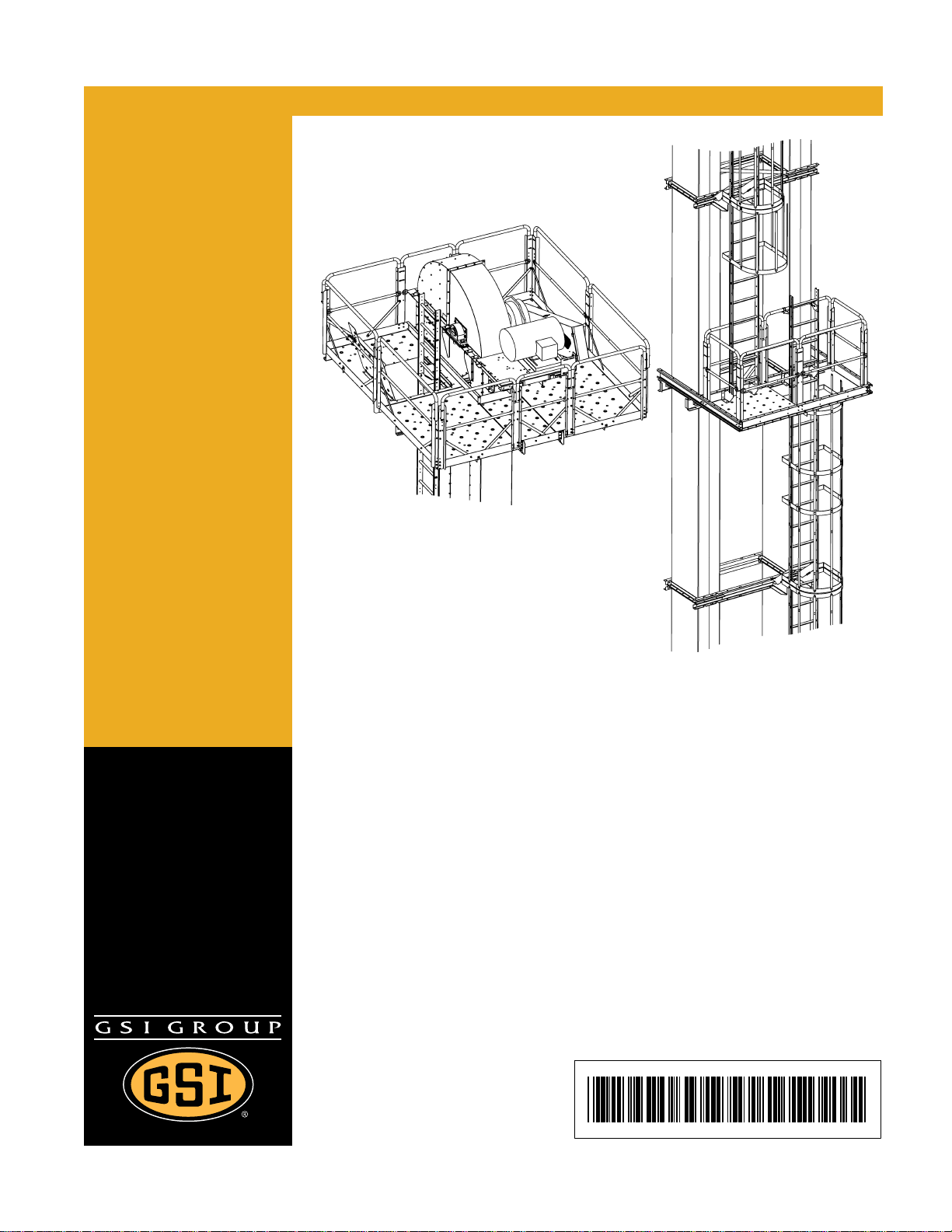
PNEG-1807CE CE Compliant 16"-24" Bucket Elevator Platform and Ladder “X” Series 3
Contents
Chapter 1 Introduction .......................................................................................................................................... 4
Chapter 2 Safety ..................................................................................................................................................... 5
Safety Guidelines .................................................................................................................................. 5
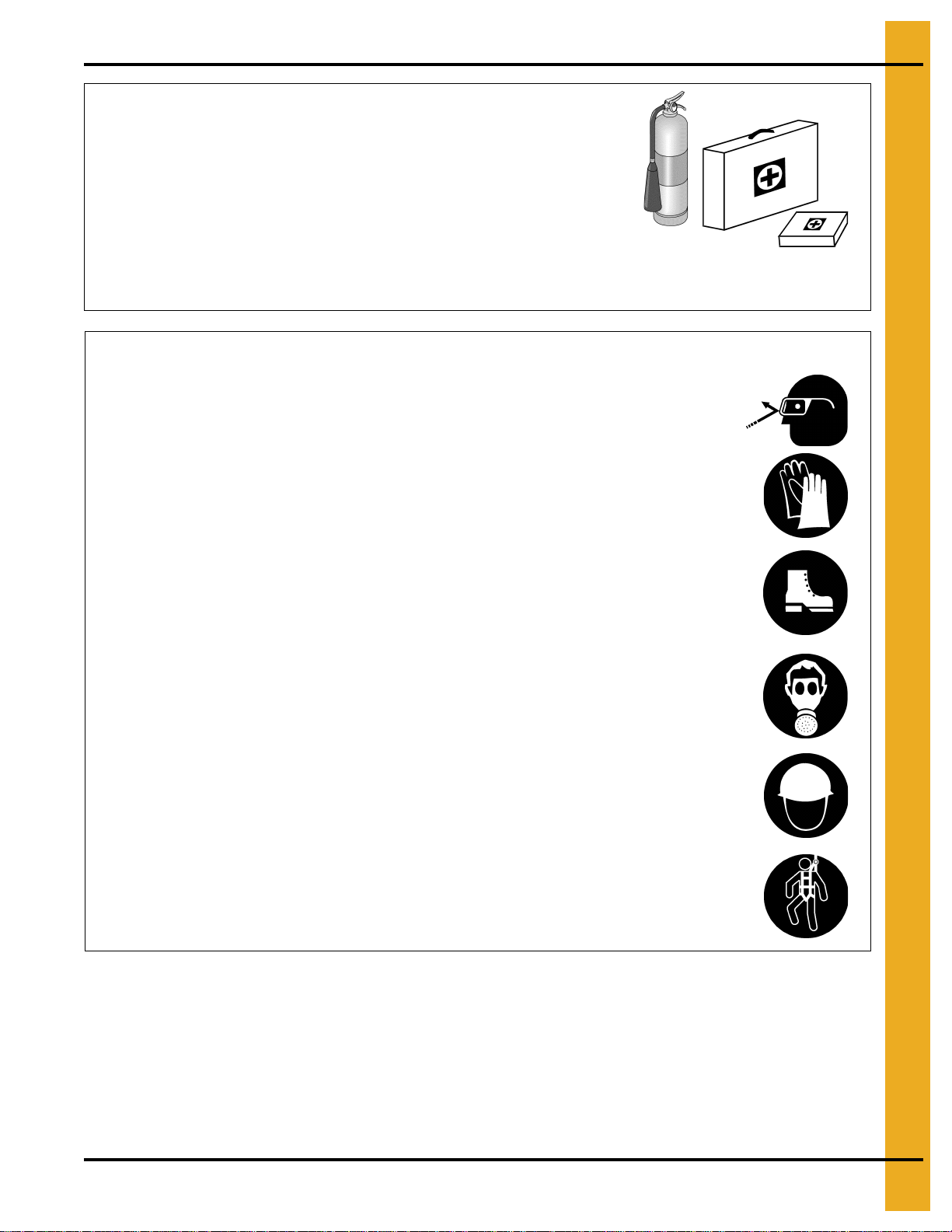
Safety Instructions ................................................................................................................................. 6
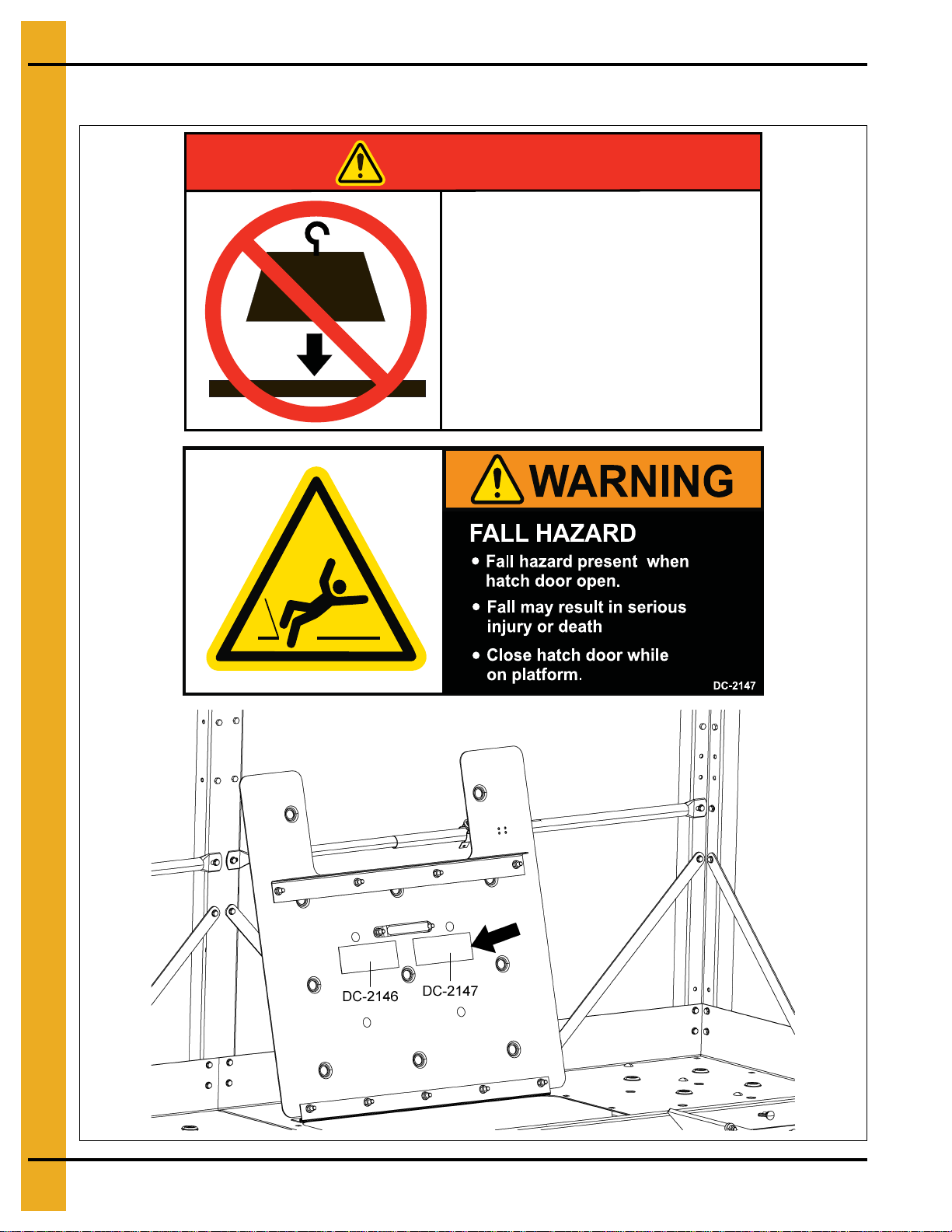
Chapter 3 Decal Location ...................................................................................................................................... 8
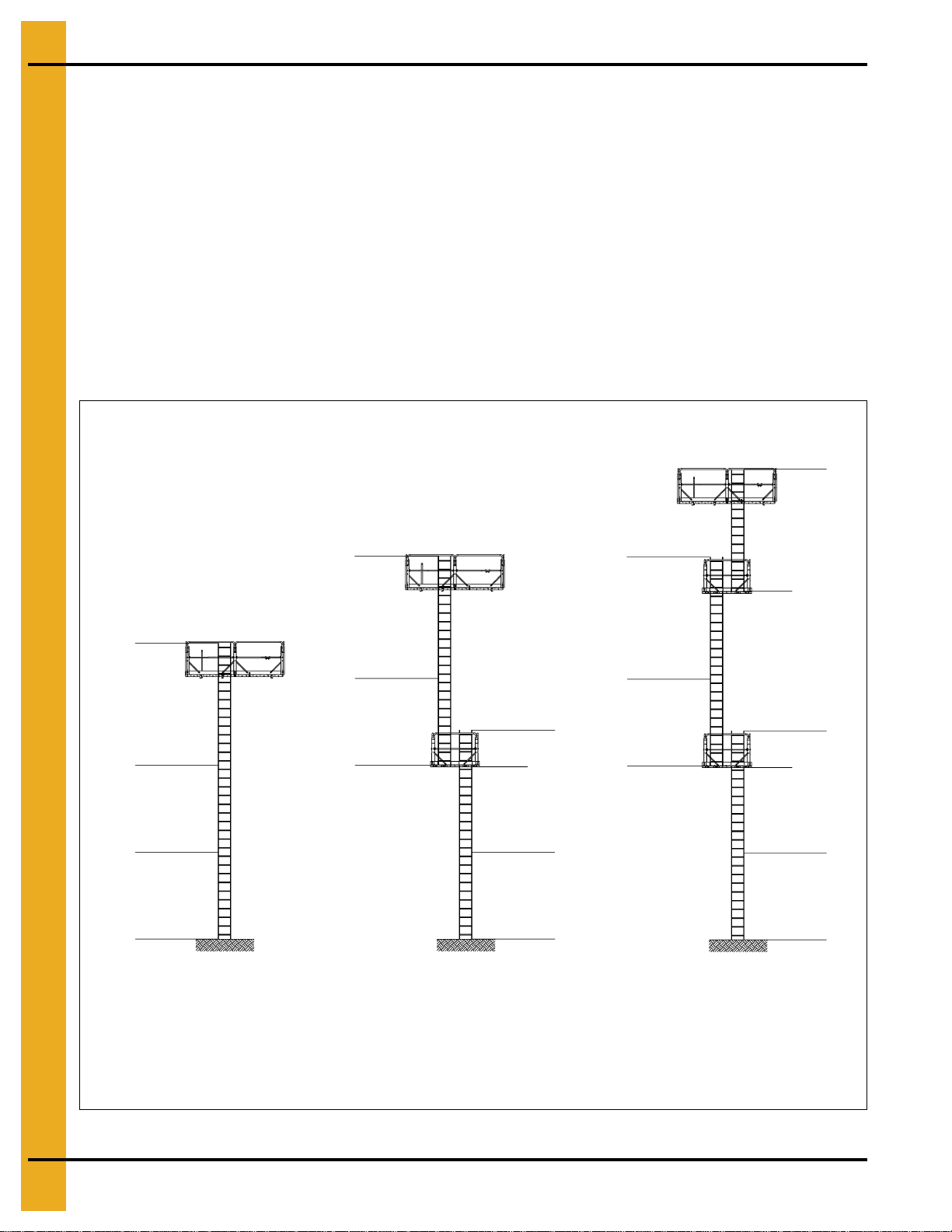
Chapter 4 Overview ............................................................................................................................................... 9
Chapter 5 Ladder Assembly ............................................................................................................................... 10
Typical Ladder/Cage Setup ................................................................................................................. 18
Chapter 6 Tie Angles, Ladder Brackets and Safety Cages .............................................................................. 19
Attach Tie Angle to Boot Trunking ...................................................................................................... 19
Attach Boot Ladder Support Brackets and Boot Ladder Section ........................................................ 20
Install Boot Ladder Section ................................................................................................................. 22
Tie Angles to Trunking ........................................................................................................................ 24
Ladder Support Brackets .................................................................................................................... 27
Attach Ladders to Ladder Brackets ..................................................................................................... 30
Safety Cage Installation ...................................................................................................................... 31
Install Safety Cage .............................................................................................................................. 32
Chapter 7 Rest Platform ...................................................................................................................................... 35
Rest Platform Tie Angles to Bucket Elevators .................................................................................... 35
Attach Rest Platform Channel to the Rest Platform Tie Angle ............................................................ 38
Rest Platform Cross Channel to Rest Platform Mounting Channels ................................................... 39
Ladder Support ................................................................................................................................... 44
Chapter 8 16"-24" Head Platform Assembly ..................................................................................................... 45
Attach Main Support Channels to Lower Head ................................................................................... 45
Install Deck A and Toe Board ............................................................................................................. 46
Install Deck A to Main Support Channels ............................................................................................ 47
Install Deck C and Toe Board ............................................................................................................. 49
Install Deck C to Main Support Channels ........................................................................................... 50
Install Deck E ...................................................................................................................................... 51
Install Adapter Bracket for 16" Platforms ............................................................................................ 53
Install Hatch Filler Plate ...................................................................................................................... 54
Install Rail Supports to Deck E ............................................................................................................ 54
Install “W” Posts (“Corner Posts” x 4) ................................................................................................. 55
Install Platform Posts .......................................................................................................................... 56
Install Intermediate Handrails .............................................................................................................. 58
Install Upper Handrails ........................................................................................................................ 60
Install Tie Braces (Safety Cage Bars) ................................................................................................. 61
Chapter 9 Install Hatch ........................................................................................................................................ 62
Chapter 10 4 x 5 Distributor Platform (Optional) .............................................................................................. 65
16"-24" Clamp Band Installation ........................................................................................................ 65
Assemble Supports (16"-24") ............................................................................................................ 69
Assemble Decking and “W” Corner Post ........................................................................................... 71
Install Handrail Posts - Non Entrance Side ....................................................................................... 73
Install Intermediate Handrails ............................................................................................................ 75
Install Safety Bar Cross Supports ...................................................................................................... 76
Install Top Handrails .......................................................................................................................... 77
Safety Gate Package (Optional) ........................................................................................................ 78
Chapter 11 Warranty ............................................................................................................................................ 79