ZHONGTIAN TDTG36/18 User manual

—1 —
BUCKET ELEVATOR
OPERATION MANUAL
江苏中天农牧机械有限公司
JIANHSU ZHONGTIAN AGRO MACHINERY CO.,LTD

—2 —
Important instruction:
1 This manual detailedly describes bucket elevator of each system structure,
function and use and maintenance method. Before installation and use of
the machine , customer should read the manual, and have a full
understanding of the ministries and its structure and function ,then have
operation and maintenance of the machine. Due to the continuous
improvement of product structure, after a certain time period, the manual of
narrative content and the actual situation of the products will have small
changes.Users should pay attention to it.
2 Please propose your advice to us for melioration when finding quality
problem or others.Thanks !

—3 —
1 GENERAL INTRODUCTION
TDTG Series Bucket Elevator is applicable for continuous and vertical elevating of
materials in shape of powder, granule and small piece. It can be widely used in the industries of
feed, cereal, oil, food, chemicals, building materials, grain depot, port and pier.
1.1 Main Performance Features
1.1.1 The structure is compact and overall dimension of cross section is small, thus floor
space can be saved remarkably;
1.1.2 Elevator foot can be fitted with direct and converse feeding hopper for users’
selection according to requirement;
1.1.3 Rubber-covering technology is used for head pulley and tail pulley so as to increase
the friction coefficient and improve the driving efficiency;
1.1.4 A transition section is added under the head pulley and fitted with outlet adjusting
plate and buffer chamber so as to reduce the return of materials and improve the capacity;
1.1.5 Elevator head is fitted with changeable wear proof plate;
1.1.6 Explosion-proof elevator housing is available and can effectively prevent the
explosion of dust;
1.1.7 Tensioner is fitted with spring buffer device so as to reduce the vibration and prevent
belt from breaking caused by sudden overload;
1.1.8 The tensioning plate is fitted with two layers of seal so as to overcome the leakage of
dust and materials from the adjusting plate;
1.1.9 Speed detector and offset alarm can be used according to users’ requirement so as
to ensure safe and normal production;
1.1.10 Anti-reverse device can be used to prevent the machine from being blocked due to
power failure;
1.1.11 The installation height is optional, but heights in Table 1 must not be exceeded.
1.2 Main Technical Parameters
Table 1 Main Technical Parameters
Parameters
Model
Head
Pulley Dia.
(mm)
Conveying capacity
Bucket
Number
(pc/m)
Rotational
Speed
(rpm)
Max. Elevating
Height
(m)
Granular
Materials(t/h)
Powder
Materials(t/h)
TDTG36/18
φ400
14.5
8
4
80
<25
TDTG36/23
φ400
26
11
4
80
<35
TDTG36/28
φ400
30
18
4
80
<35
TDTG50/28
φ500
76
30
5
84
<45
TDTG60/30
Φ600
108
62
5
84
<45
2 STRUCTURE FEATURES AND WORKING
PRINCIPLE

—4 —
2.1 General Structure
TDTG Series Bucket Elevator mainly consists of elevator head, elevator casing, bucket,
bucket belt, elevator foot and drive. Elevator head, elevator tail and elevator casing flanges
are connected with bolts and sealed with sealing gasket. Buckets are fixed to the bucket belt
with special-purpose bucket bolts.
Table 2 Overall Dimension of TDTG Series Elevator
Item
Model
Elevator Foot Size
Elevator Head Size
A1
A2
A3
B1
B2
B3
h
h1
h2
n1-g1
A4
B4
h3
TDTG40/18
3×224
798
1506
286
316
410
1150
388
188
8-φ16
1206
622
1126
TDTG40/23
3×235
850
1558
346
376
470
1150
388
188
8-φ16
1258
682
1126
TDTG40/28
3×235
850
1558
396
426
520
1150
388
188
8-φ16
1258
732
1126
TDTG50/18
2×396
900
1868
286
316
474
1300
375
200
6-φ16
1342
855
1186
TDTG50/23
2×422
952
1922
346
376
514
1300
375
200
6-φ16
1417
915
1186
TDTG50/28
2×422
952
1922
396
426
564
1300
375
200
6-φ16
1417
965
1186
Item
Model
Inlet Size
Inlet Size
a1
a2
a3
b1
b2
b3
n2-φg2
a4
a5
a6
b4
b5
b6
n3-φg3
TDTG40/18
255
354
2×147
250
2×143
316
8-φ9
280
319
2×159
250
2×143
316
8-φ9
TDTG40/23
255
354
2×147
310
3×115
376
9-φ9
280
319
2×159
310
3×115
376
10-φ9
TDTG40/28
255
354
2×147
360
3×132
426
9-φ9
280
319
2×159
360
3×132
426
10-φ9
TDTG50/18
380
545
3×135
250
2×143
316
9-φ9
300
339
2×174
250
2×143
316
8-φ9
TDTG50/23
380
545
3×135
310
3×115
376
10-φ9
300
339
2×174
310
3×115
376
10-φ9
TDTG50/28
380
545
3×135
360
3×132
426
10-φ9
300
339
2×174
360
3×132
426
10-φ9
2.2 Working Principle and Working Process
After being turned on, motor drives the head pulley through sprocket and chain and
transmits power to bucket belt. Buckets move from bottom to top circularly along the casing
together with bucket belt. When buckets full of materials pass the head pulley, materials, under
the action of centrifugal force and gravity, are thrown out of the buckets and discharged from
the outlet along the housing.
2.3 Structure of Main Parts and their Working Principle
2.3.1 Elevator Head
It consists of elevator head base, head pulley, head pulley shaft and elevator housing and
is fitted with adjustable materials-returning device and buffer chamber to reduce the return of
materials.
2.3.2 Casing
It consists of common casing, air pressure balance casing, maintenance cassing and
explosion proof casing. The standard length of common casing is 2m for each section. Air
pressure balance casing is mounted in the elevator casing through flanges (The installing

—5 —
position and quantity shall be determined according to requirement) so as to make air pressure
in two casings keep balanced and ensure that materials are fed to and discharged out of the
buckets smoothly. There is access door in the maintenance casing for observation and
replacement of buckets and bucket belt.
2.3.3 Elevator Foot
It consists of elevator foot housing, tail pulley, tail pulley shaft, tensioner and feeding
hopper. Elevator foot is fitted with direct and converse feeding hoppers which can meet the
different requirement of users. Tensioner is used to adjust the relative position of head pulley
and tail pulley and tension the bucket belt so as to prevent the offset and slipping. Elevator feet
are fitted with discharging flapper at both sides for removing the remaining materials and
impurities inside the machine.
2.3.4 Buckets and Bucket Belt
Bucket includes steel bucket and light high-strength plastic bucket. Users can make choice
according to the property of materials. Buckets are fixed to the bucket belt with special-purpose
bucket screws in certain spacing.
Bucket belt is the strengthened fabric rubber belt with low stretching rate, high strength,
wear proof quality, low weight and without toxicity and smell.
3 INSTALLATION, ADJUSTMENT AND COMMISSIONING
3.1 Installation Conditions
3.1.1 The foundation for elevator foot is poured with concrete and has a thickness not
lower than 300mm. It is required to be level and solid enough to bear the weight of the machine
and meet the requirement of load in the running process.
3.1.2 The foundation should have the embedded anchor bolts or steel plate with foot with
size larger than elevator foot.
3.1.3 When elevator housing need pass through the floors, floors should have the
reserved holes. Long hole is recommended for convenience of installation and adjustment. See
Figure 4 and Table 3 for sizes.
3.1.4 There should be sufficient space not smaller than 500mm between cover of elevator
head and building (or structural member).
3.1.5 The access door of the housing (central line) should be arranged in a position
about 1400mm away from the floor or ground for convenience of inspection and repair.
3.1.6 The working bench for installing the drive should be installed on the floor (or platform
of structural member) and fixed with anchor bolts.
3.1.7 It should be designed that a working platform is available at the part of head pulley
for convenience of operation and repair.
3.2 Installation
3.2.1 Position the elevator foot on the finished foundation, take the flange face of elevator
foot as datum for aligning (it is allowed to insert the leveling iron pad with thickness not larger
than 40mm) with deviation not higher than 1/1000, and fix the anchor bolts.
3.2.2 Mount the housings section by section from bottom to top according to the
requirement of technological design, and use seal for sealing.

—6 —
3.2.3 Mounting of Drive
Motor, reducer, coupling, drive bracket and guard have already been assembled before
the delivery. To mount the drive to the elevator body, the detailed requirement of Assembling
General Drawing should be followed and the drive should be fixed to drive platform or head
housing. The drive may become loose due to transportation or other factors, so check should
be made prior to installation and starting. After the drive is fixed, check to see if the connecting
bolts become loose and if coupling reach the requirement of installation.
3.2.4 When elevator has drive platform, the parallelism allowance of installation datum
plane of reducer on the platform to level should not be larger than 1mm.
3.2.5 When mounting bucket belt and buckets, firstly adjust the tail pulley base of elevator
foot to the top position, and then pull the pre-stretched bucket belt in from elevator head. One
end rounds the tail pulley and is pulled out of the access door, and is connected with another
end. Bucket belt adopts lap joint or angular joint. For lap joint, it would be better that length of
lap joint section equals the length of 3-5 buckets. See Figure 5 for lap joint and Figure 6 for
angular joint. Then mount the buckets one by one to the bucket belt at the access door of
bearing branch section. The central line of bucket should align the central line of bucket belt
with deviation not larger than 4mm. For users who have the inspecting and repairing motor,
after mounting the drive and connecting the power, they can start the inspecting and repairing
motor by touch to drive the belt and then mount buckets one by one.
3.2.6 After mounting the buckets, adjust the tensioner to make bucket belt be tensioned to
proper extent. Observe the position of tail shaft and take note that the remaining tension stroke
is not less than 50% of total stroke. If it is not qualified, connect the belt again until it is qualified.
3.2.7 Adjust the position of return retainer at elevator head to make the gap between it and
outer edge of bucket keep at 5mm-10mm.
3.2.8 The arrangement of position of elevator head should follow the requirement of
technological process. Its discharging outlet and feeding inlet of elevator foot can be arranged
in same side (The feeding type is direct feeding), also in opposite side (The feeding type is
converse feeding). The fill-up coefficient of bucket for converse feeding is higher than that of
bucket for direct feeding. Converse feeding type is recommended.
3.2.9 Quality Requirement and Inspection Method of Casing
After mounting of the casing is finished, the mounting quality should be checked by using
the following method. If there is anything not meeting the requirement, the casing cannot be
fixed until correction is made by means of adding the pad.
3.2.9.1 The parallelism allowance of upper plane of elevator foot to level is not larger than
1.2mm.
3.2.9.2 The parallelism allowance of head pulley shaft to level is not larger than 0.3/1000.
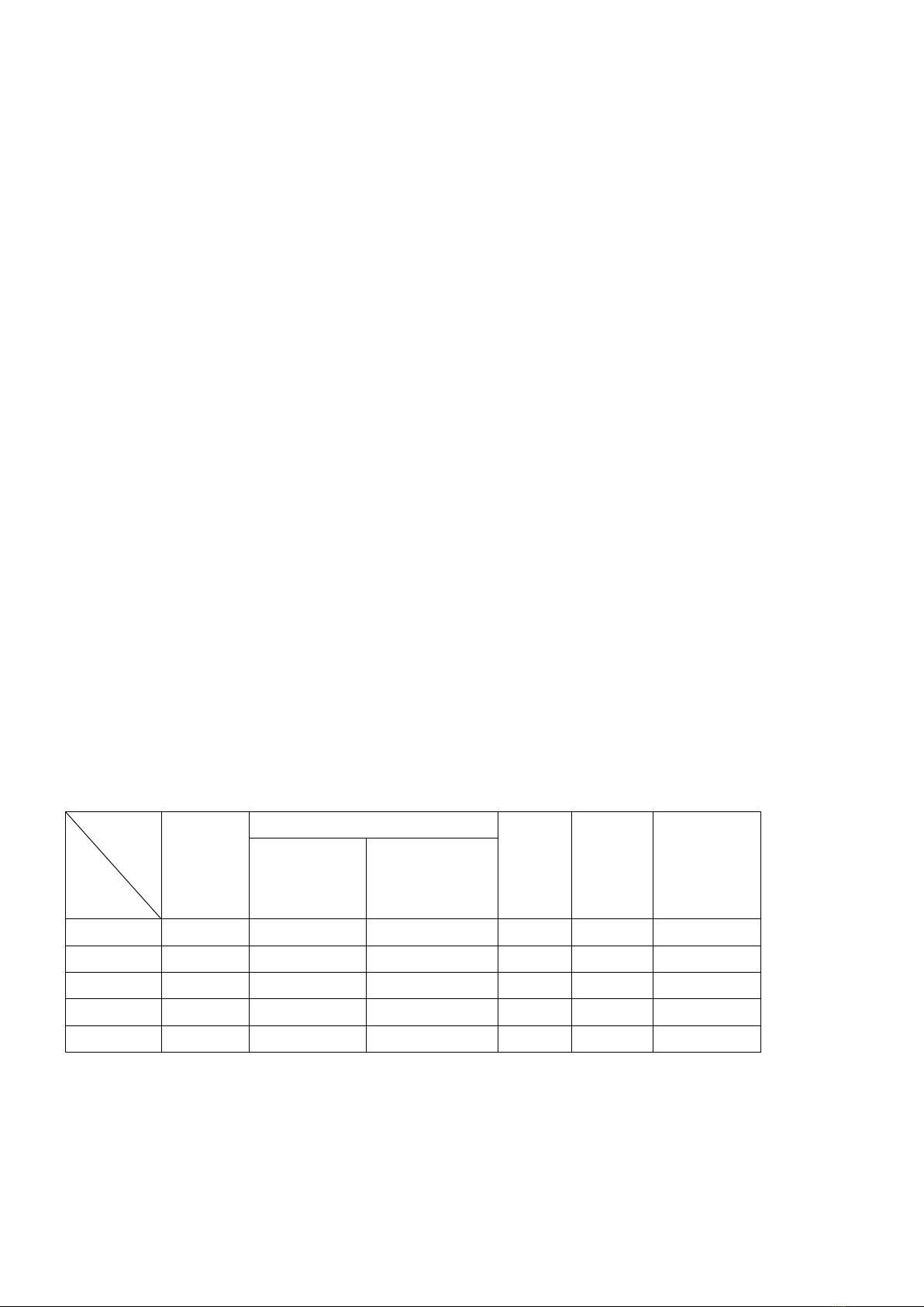
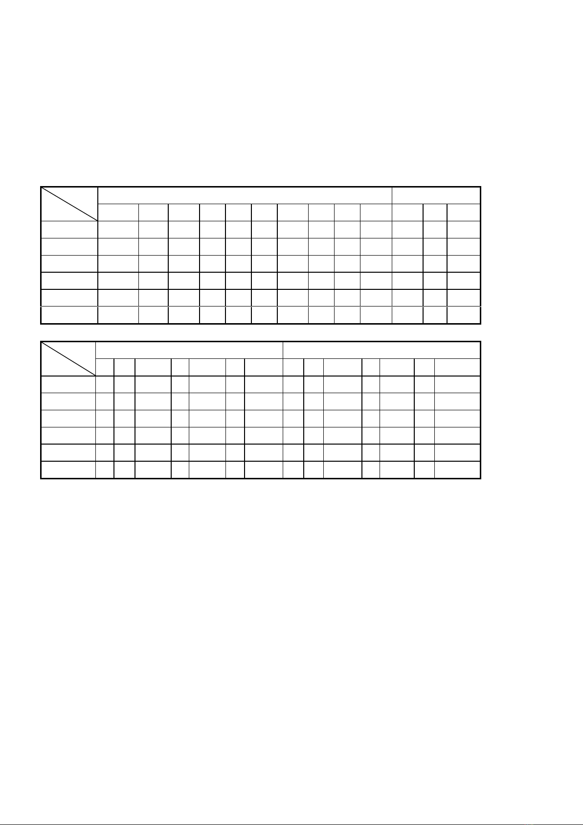
3.2.9.3 Check the perpendicularity and curvature and see Table 4 for requirement on
deviation.

—7 —
Table 4 Deviation of Perpendicularity and Curvature
Measuring
Position
Elevating Height H(m)
<7
7-30
>30
Deviation(mm)
|A1-A2|
4
6
8
|B1-B2|
3.2.9.4 See Figure 8 for mounting of tail pulley shaft and see Table 5 for requirement on
deviation.
Table 5 Installing Deviation of Tail Pulley Shaft
Measuring Position
Elevating Height H(m)
<7
7-30
>30
Deviation(mm)
|B1-B2|
5
7
9
|A0-A1|
3
5
7
3.3 Adjustment
3.3.1 Adjustment of Tensionness of Bucket Belt (Tensioner of Screw Rod)
3.3.1.1 Turn the screw rod with spanner and push the bearing housing of tail pulley
downwards to tension the bucket belt; if turning the screw rod conversely, the bearing housing
will be pushed upwards.
3.3.1.2 Adjust the tensioner at another side by using the same method. During the
adjustment, the height of bearings at two sides should be same.
3.3.1.3 After tensionness is adjusted, the fixing nuts must be fastened so as to prevent
elevator from becoming loose in the running process.
3.3.1.4 Gravity tensioner can be used to adjust the tensionness of bucket belt through
increasing or reducing the balance.
3.3.2 Adjustment of Return Retainer (See Figure 9)
3.3.2.1 Open the sight cover of the elevator head base.
3.3.2.2 Adjust the gap between return retainer and bucket and keep it at 5-10mm.
3.3.2.3 Fix the return retainer and close the sight cover.
3.4 Unloaded Trial Run
3.4.1 Preparation prior to Trial Run
3.4.1.1 Add the lubricator.
3.4.1.2 Open the discharging flapper of elevator foot and get rid of the impurities inside.
3.4.1.3 Check to see if bucket belt has proper tensionness, straight joint and correct lap
joint direction.

—8 —
3.4.1.4 Check to see if fasteners become loose.
3.4.1.5 Check to see if gap between return retainer and bucket is proper.
3.4.1.6 Remove the reverse stopper and adjust the rotation direction of motor. Mount the
reverse stopper after the rotation direction is correct.
3.4.1.7 Start the motor by touch and check to see if there is abnormal noise.
3.4.2 Unloaded Trial Run
3.4.2.1 Race the machine for 2 hours, meanwhile adjust the tensionness of bucket belt
and remove the offset and slipping of bucket belt.
3.4.2.2 Check to see if reducer leaks oil and produces abnormal noise.
3.4.2.3 The bearing should not have a rise of temperature exceeding 40℃and should
have good lubrication.
3.4.2.4 After racing the machine for 4 hours, stop the machine and check to see if bearings,
fasteners, buckets, connecting screws of bucket belt and lubricated parts are normal.
3.5 Points for Attention in Loaded Trial Run
3.5.1 After the machine is started, materials should be fed gradually, and the running with
full load is not allowed until all is normal. If return of materials is excessive, retainer can be
adjusted. It would be better that gap between bucket and retainer is about 5-10mm.
3.5.2 To elevate the powder materials, 2 rows of Φ6 hole can be made at the bottom of
bucket so as to reduce the negative pressure and make the feeding and discharging of powder
materials smooth.
3.5.3 The hopper should receive the materials smoothly, and feeding should be even at
the feeding inlet and excessive feeding is not allowed. If materials blockage occurs, stop the
machine in time and open the discharging flapper at the bottom of elevator foot to get rid of
materials. It is prohibited to stretch hands into the elevator foot for handling the materials in the
discharging process.
3.5.4 The reverse stopper should work reliably without reverse.
3.5.5 Bucket belt should not slip during the running with full load. If it slips, speed detector
(if any) should act and stop the machine.
3.6 Electric Control
3.6.1 See Figure 10 and Figure 11 for Diagram of Electric Control Principle.
3.6.2 The machine and electric control box should have good earthing.
3.6.3 The installation and operation of electric components should follow their operation
manuals. They are required to work safely and reliably.
4 OPERATIONS
4.1 Preparation and Check prior to Operation
4.1.1 Before operating the machine, please carefully read this operation manual and know
how to operate this machine correctly so as to avoid unnecessary loss;
4.1.2 Materials to be elevated should conform to the bucket type;
4.1.3 Before starting the machine, make regular check, that is, check the fasteners, safety
guard and lubrication.

—9 —
4.2 Operation
4.2.1 To use the machine, firstly start the follow-up equipment of the machine, then start
the elevator, and then start the preceding equipment from back to front in turn, finally feed the
materials.
4.2.2 The machine should be started without load. Materials cannot be fed until the
running without load is normal. Adjust the feeding slide properly and keep the coming flow rate
smooth and proper so as to prevent the blockage caused by excessive feeding. Once the
feeding slide is adjusted and positioned, careless action is not allowed.
4.2.3 Check to see if bucket belt has offset and slipping. Make adjustment in time.
4.2.4 In the normal running process, it is prohibited to open the guard of elevator head or
pull out the flapper of elevator foot.
4.2.5 The remaining materials in the feeding hopper should be removed in time.
4.2.6 If there is no special condition, stopping with load is not allowed. Generally
speaking, before stopping the machine, firstly stop the feeding, and then race the machine for
1-3 minutes. The machine cannot be turned off until the materials in the machine are
discharged.
4.2.7 The stopping sequence is opposite to the starting sequence.
5 TROUBLES AND TROUBLESHOOTING
Table 6 Trouble and Troubleshooting
Trouble
Cause
Troubleshooting Method
Materials
return.
(1)Follow-up equipments are in
trouble.
(2)Feeding amount increases
suddenly.
(3)Retainer is not adjusted properly
and gap between it and bucket is
excessive.
(1)Stop the machine and remove the trouble of
follow-up equipment.
(2)Adjust the feeding slide and control the feeding
amount of materials.
(3)Open the elevator head and adjust the retainer.
The machine
has
abnormal
noise.
(1)Foreign materials enter the
machine.
(2)Bucket bolts become loose and
buckets come off and are damaged.
(3)Gap between bucket and retainer is
too small and there is collision.
(4)Bucket belt becomes loose or
offsets and buckets touch the housing.
(1)Stop the machine and clear away the foreign
materials in the machine.
(2)Open the access door of repair housing, fix the
bucket bolts and replace the come-off and damaged
buckets.
(3)Open the access door of elevator head and
adjust the retainer.
(4)Adjust the tensioning bolts to tension the bucket
belt and eliminate the offset.
The machine
is blocked by
materials.
(1)The discharging outlet or slide pipe
is blocked by foreign materials.
(2)The feeding amount is excessive
(1)Remove the foreign materials at the discharging
outlet or in the slide pipe.
(2)Correct the flow rate of materials.

—10 —
and exceeds the technical
performance of the machine.
(3)Drive or electric control is in trouble
and cause sudden stoppage.
(3)Remove the trouble of drive or electric control.
6 MAINTENANCE
6.1 Buckets and bucket belts should be checked and repaired completely once every
month. If finding that they become loose or are damaged, fix or replace them in time. Complete
check should be made and parts should be fixed or replaced during the annual overhaul.
6.2 The rolling bearing should be lubricated with #2 lithium based lube once every month.
It should be disassembled for cleaning once and lube should be replaced during the annual
overhaul.
6.3 In the running process, iron, large-piece hard materials and impurities should be
prevented from entering the elevator so as to avoid the damage of the machine. The feeding
inlet and discharging outlet should be fitted with grids. Often check these two positions to see if
there are foreign materials and come-off buckets.
6.4 When bearing need be replaced, remove the mounting bolts of bearing (Driving parts
should be firstly removed from the driving end), then bearing can be removed and replaced.
6.5 Maintenance of motor, gearbox, hydraulic coupling should follow their operation
manuals.
6.6 Check the rise of bearing temperature. If exceeding 40℃, stop the machine for check
and removal of trouble.
6.7 When checking and repairing the elevator head, firstly remove the connecting bolts of
elevator head cover and use ears to remove the elevator head cover. It is prohibited to use
ears at the elevator head to lift the machine.
6.8 Generally speaking, the elevator should have a current once every quarter and an
overhaul once every year.
7 TRANSPORTATION AND STORAGE
7.1 Collision is prohibited during the transportation so as to prevent the machine housing
from deforming or prevent paint on the surface from being damaged, thus prevent appearance
quality from being influenced. And damp proof measures should be taken to prevent the
machine from becoming damp and rusting.
7.2 When the machine will be laid aside for a long time, it should be kept in a
well-ventilated, dry and cool place, and there should be damp proof facilities. The exposed
surface not coated with paint should be coated with antirusting oil.

—11 —
8 WEARING PARTS
Table 7 List of Easily-worn Parts
No
Model
Elevator
Head Bearing
Elevator
Tail Bearing
Bucket
Model
Bucket Belt
(width mm)
Remarks
1
TDTG40/18
UCP210
F90509
18/14
200
2
TDTG40/23
UCP210
F90509
23/14 19/14
250
3
TDTG40/28
UCP211
F90509
28/14
300
4
TDTG50/18
SN518
F90511
18/14
200
5
TDTG50/23
SN518
F90511
23/16
250
6
TDTG50/28
SN518
F90511
28/16
300
9 CAUTIONS
9.1 During the operation of equipment, any parts of human body must not touch the
rotating parts of equipment so as to avoid the human body injury accident.
9.2 To inspect or repair the equipment, equipment must be turned off.
9.3 When the machine is running, the discharging flapper at both ends of elevator foot
must not be opened. Cleaning must be done after the machine stops.

—12 —
江苏中天农牧机械有限公司
JIANGSU ZHONGTIAN AGRO MACHINERY CO.,LTD
ADD: No.7 ZhongDaLi Road,New industrial Park,
DaiBu Town,LiYang,JiangSu,China.
P C:213300
Tel:13814760009
Fax::0086-519-87256670
Http://www.jsztmt.com
E-mail:info@jsztmt.com
This manual suits for next models
4
Table of contents