OMS Hypodrive EC 2-25 Lift User manual
OMS Antriebstechnik
Bahnhofstraße 12
36219 Cornberg
Deutschland
elephone:
+49 (0) 5650 / 969-0
elefax: +49 (0) 5650 / 969-100
Translation from german original
Installation instructions
according to Annex VI of the EC Directive 2006/42/EC Mechanical Equi ment
and further roduct details
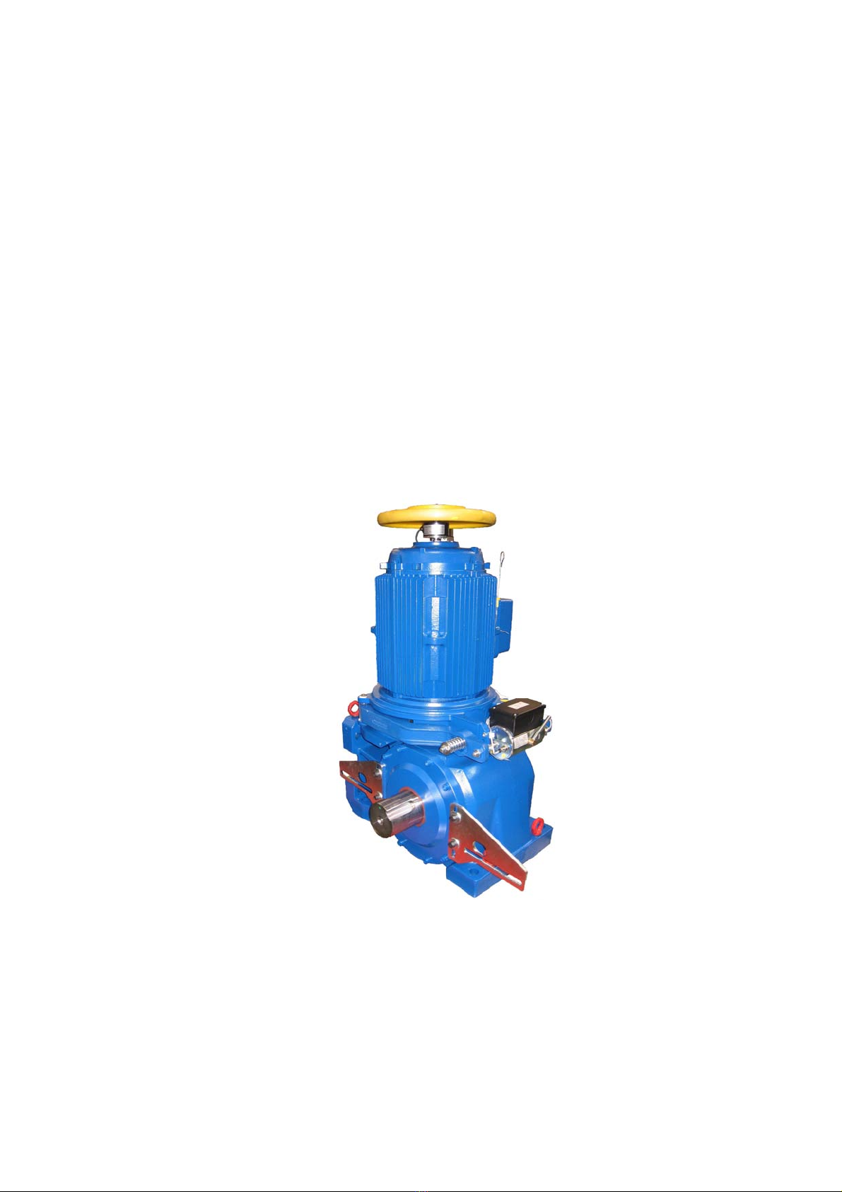
Elevator machine
MODEL:
oms
Hy odrive EC 2-25 Lift
Keep this document for future reference
OMS No. Date of manufacture
Month / Year


Installation Instructions EC 2-25 Lift
(Subject to technical alterations! - Status 09 2018)
This is a translation. The German original shall prevail.
Contents
Page
1
INTRODUCTION 1
2
SAFETY INSTRUCTIONS FOR OMS ELEVATOR DRIVES 2
2.1
Intended use 2
2.2
Im ro er use 3
2.3
Warranty and liability for the drive 5
2.4
Hazards associated with the elevator drive 5
2.5
Instructions for safe use 6
2.6
Installation and maintenance ersonnel requirements 6
2.7
General information 6
3
COMMISSIONING 7
3.1
Installation 7
3.1.1
Installation instructions 7
3.1.2
Mount and connect the complete elevator machine 8
3.1.3
Mount and adjust the safety device to prevent rope jumping 10
3.2
Installation and o eration of the emergency release 11
3.3
Install the ro e clam 12
4
CONSTRUCTION AND FUNCTION 13
4.1
Technical data 14
4.2
Noise emission information 14
4.3
Manufacturer’s data late 14
4.4
Com onents and add-on arts - s are arts 15
4.5
Alternative configurations 15
4.6
Gear variants and installation ositions 15
5
TRANSPORT AND STORAGE 18
5.1
Trans ort 18
5.1.1
Lifting the machine 19
5.2
Storage 20
6
OPERATION AND MAINTENANCE 22
6.1
Recommended routine maintenance 22
6.2
Errors – Troubleshooting 23
6.3
Gear oil 23
6.3.1
Checking the oil level 23
6.3.2
Checking the condition of the oil 23
6.3.3
Changing the oil 24
6.4
Re lacing the traction sheave 25
6.5
Brake maintenance 26

Installation Instructions EC 2-25 Lift
(Subject to technical alterations! - Status 09 2018)
This is a translation. The German original shall prevail.
6.5.1
Manual release lever 26
6.5.2
Check: Ensure the brake lever moves easily 27
6.5.3
Check: Clearance and lining wear 27
6.5.4
Replacing the brake lever 28
6.5.5
Adjusting the brake 28
6.5.6
Adjusting the braking torque, dual circuit braking system: 29
6.6
Adjusting the braking function sensor 30
6.7
Adjusting the break lining wear control 31
6.8
Re lacing the incremental encoder 32
6.9
Re lacing the motor 32
6.10
Re lacing the elastic cou ling ring 33
7
DISASSEMBLY 34
7.1
Drive unit disassembly 34
7.2
Drive unit dis osal 34
8
APPENDIX 35
A Technical data OMS - elevator machine EC 2-25 Lift 36
B Dimension drawing OMS - elevator machine EC 2-25 Lift 37
C Electrical connections 41
D Traction sheave 47
E Technical releases 48
F EU safety data sheet Klübersynth GH 6-220 49
Installation and Maintenance Manual EC 2-25 Lift
(Subject to technical alterations! - Status 06 2011)
This is a translation. The German original shall prevail.
Page 1 of 50
1Introduction
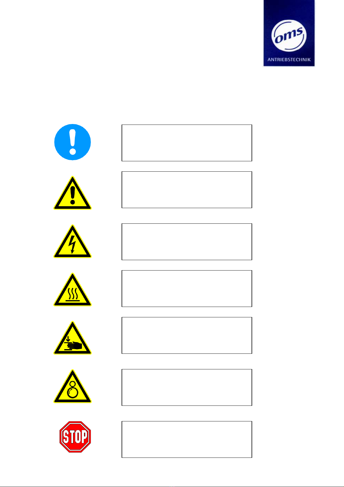
Warning and safety information in these instructions is presented as pictographs indicating haz-
ards and furnishing additional information.
Note on use:
Additional information and tips
No hazard
Warning:
General hazard
Potential damage to system and
injury to persons
Warning:
Hazardous voltage levels
Potential hazard
Serious or fatal injury to persons
Warning:
Hot surface
Potential hazard
Serious injury to persons or damage to equip-
ment
Warning:
Crush or pinch points
Potential hazard
Serious injury to persons
Warning:
Entanglement and entrapment
Potential hazard
Serious injury to persons or damage to equip-
ment
Warning:
Extreme danger
Potential injury to persons and damage to
equipment
Serious or fatal injury to persons

Installation Instructions EC 2-25 Lift
(Subject to technical alterations! - Status 09 2018)
This is a translation. The German original shall prevail.
Page 2 of 50
2Safety instructions for OMS elevator drives
2.1 Intended use
OMS elevator machines EC 2-25 Lift are designed and intended exclusively for installation and
use in electrically operated traction sheave elevators for the conveyance of persons or goods in
accordance with EN 81-1.
Use for any other purpose that the intended use as specified above is considered improper use.
OMS ANTRIEBSTECHNIK disclaims all liability for any damage or injury resulting from such im-
proper use or from errors of procedure or method.
All planning, installation and maintenance work must without exception be carried out by
qualified specialist personnel.
Qualified personnel is defined as persons who due to their education and training, special
training, instruction and experience as well as their knowledge of all pertinent norms and
standards and general and statutory specifications, requirements and regulations, accident
prevention regulations and operating conditions as authorised by those responsible for the
safety of the system to carry out the necessary work and thereby recognise and avoid potential
hazards. (Qualified personnel as defined in IEC 364).
This OMS elevator drive falls within the scope of application of the 9
th
Directive of the Ma-
chine and Product Safety Law (9. Verordnung zum Geräte- und Produktsicherheitsgesetz) and
the Machinery Directive 2006 42 EC and is a machine part to be subsequently installed for its
intended use in an elevator system and is thus without the CE mark.
Commissioning is prohibited until the installer (see Machine Directive 95 16 EC) has properly
installed the product in the designated elevator system and the CE mark has been affixed to
the elevator system to show that the safety requirements for the product as supplied by the
manufacturer are fulfilled.
All other applicable or pertinent regulations and legal requirements (e.g. on operation, mainte-
nance and inspection) remain in force.
OMS does not accept any responsibility, liability or warranty whatsoever for any damage what-
soever caused by improper, unprofessional or other actions which do not comply with these in-
stallation and maintenance instructions and or do not comply with the aforementioned norms
and standards and are thus detrimental to the product properties and characteristics.
The motors are designed exclusively for use with frequency converters. Customer supplied fre-
quency converters must be adjusted in accordance with the appropriate instruction sheets to
comply with OMS elevator machine characteristics, properties and requirements. Adjust the
frequency converter parameters to the motor output of the drive.
The drive is designed exclusively for use within an enclosed area (e.g. elevator shaft or machine
room).

Installation Instructions EC 2-25 Lift
(Subject to technical alterations! - Status 09 2018)
This is a translation. The German original shall prevail.
Page 3 of 50
The storage, installation and or operation areas for OMS drives must be closed and dry. The fi-
nal customer and the user must ensure that appropriate protective measures are implemented
to avoid any contamination whatsoever due to any building dust or dirt.
When running, the machine may only be stopped via the frequency converter and machine
brake.
OMS elevator machines may only be operated when in technically perfect condition and when
within the parameters as specified by OMS.
Intended use also includes:
•Compliance with the operating instructions
•Compliance with the statutory accident prevention and environmental regulations
•Compliance with and adherence to the elevator documentation elevator regulations and
specifications.
2.2 Im ro er use
OMS drives may not be operated in potentially explosive environments or corrosive atmos-
pheres.
The shoe brake with double circuit double acting expansion solenoid is designed for only a lim-
ited number of emergency stops. Using it as a working brake is deemed improper use.
Exceeding the permissible limits for use constitutes improper use.
Permissible limits:
•Max. motor speed: see technical documentation;
•Max. static load on the traction sheave, see technical documentation;
•Max. number of journeys hour = 240;
•Ambient temperatures during operation min.: 5° C, max.: 40° C;
•The technical data and specifications on the motor manufacturer’s data plate are only valid
for installation heights up to h ≤ 1000m above NN.
•Max. rel. humidity: 85% at 20°C (non-condensing)
•Operation under extreme climatic conditions must be clarified with OMS.
The following in particular also constitute improper use:
-Operation without oil or with oil other than that specified
-Securing the drive with bolts that are weaker than the specified bolts
-Opening the gear unit in situ after it has been installed
Installation Instructions EC 2-25 Lift
(Subject to technical alterations! - Status 09 2018)
This is a translation. The German original shall prevail.
Page 4 of 50
Important:
•All work connected with the transport, electrical connections, commissioning
and maintenance and servicing of the drive must only be carried out by quali-
fied specialist personnel. Improper actions can cause serious injuries and equip-
ment damage.
Caution!
Important note on elevator machine EC 2-25 Lift:
•The high efficiency of the elevator machine means the self-locking capacity is
negligible, i.e. the drive will start to move immediately as soon as the brake is
released.
•When installing the safety catching device, the brake system must be fully functional and
guarantee that the service brake is ready to be applied immediately at any times.
•Elevator machine operation without a fully functional safety catching device is prohibited.
The operator has sole liability for all and any injuries and damage.
•Recurring checks and tests may not lead to excessive wear, stresses or strains which could
impair the operational safety of the elevator.
Periodic tests can be done with test weights and nominal speed
Alternatively the tests can be done with an empty car and nominal speed ( up to v = 2ms
-1
).
•Releasing the elevator car from the safety catching device may only be done by moving the
elevator car in the opposite direction to the direction that caused the safety catching device
to activate. Under all operating conditions, the elevator drive may only be operated with the
max. permissible loads as specified by the elevator specifications. All and any procedures and
applications causing additional static and dynamic loads (torque, force, vibration etc.) on the
elevator drive e.g. on the traction sheave, motor, brake, housing, are prohibited. OMS refuses
all and any warranty and or liability claims if this is not complied with, irrespective of legal
basis.
•Ensure the motor does not rest on or against the mounting frame. Take appropriate measures
to ensure the above and check that this is done in each and every case. Record these
measures in a protocol as documentary proof.

Installation Instructions EC 2-25 Lift
(Subject to technical alterations! - Status 09 2018)
This is a translation. The German original shall prevail.
Page 5 of 50
2.3 Warranty and liability for the drive
•The manufacturer of the drive only guarantees proper and safe functionality of the drive if
the specifications provided with each drive are observed and if proper assembly (installation)
maintenance, testing and operation of the drive is in accordance with the maintenance in-
structions and the procedures stipulated here.
•The warranty is void if the permissible limits are exceeded during operation, maintenance or
testing.
•The customer is responsible and liable for the proper assembly (installation), maintenance,
testing and operation of the drive and must furnish proof that only trained and qualified
specialist personnel are employed.
•Should errors, defects or non-conformances be detected on the elevator system including the
drive, the system must be disabled immediately, otherwise the operator is solely liable for all
and any injuries to persons or damage to equipment irrespective of legal basis.
•Incorrect installation and or improper operation of the system, in particular with respect to
the aforementioned improper procedures or changes or modifications made to the drive or
its components irrespective of legal basis always lead to the complete and absolute non-
liability of the drive manufacturer and the invalidity of the guarantee and warranty.
•OMS refuses all and any warranty and or liability claims when the installer, operator and or
maintenance company does not furnish complete and continuous documentary proof that
the described permissible system and procedures and uses for the elevator system including
drive have been complied with (e.g. elevator book etc.).
2.4 Hazards associated with the elevator drive
The elevator drives are state of the art and are safe to operate at delivery. Any changes or
modifications, in particular when detrimental to operational safety, are prohibited.
The traction sheave and the handwheel of the elevator machine EC 2-25 Lift provided by OMS
do not have safety covers and may only be used in a locked machine room. When persons are
in the machine room, ensure adequate safety distance is kept to all moving and rotating parts
(marked in yellow).
The elevator manufacturer must provide safety protection equipment on and for each moving
or rotating part.

Installation Instructions EC 2-25 Lift
(Subject to technical alterations! - Status 09 2018)
This is a translation. The German original shall prevail.
Page 6 of 50
2.5 Instructions for safe use
Should changes be detected during the service life of the machine, e.g. due to wear, ageing
etc., remedy these immediately in accordance with these installation and maintenance instruc-
tions.
The gear unit may only be opened by OMS in the OMS factory, otherwise the warran-
ty guarantee is invalid and OMS refuses all and any warranty and or liability claims.
2.6 Installation and maintenance ersonnel requirements
Commissioning, maintenance and or repairs on the electrical parts of the machine may only be
carried out by trained and qualified personnel.
Qualified personnel:
Qualified personnel is defined as persons who due to their education and training, experience,
special training and instruction as well as their knowledge of all pertinent norms and standards
and general and statutory specifications, requirements and regulations, accident prevention
regulations and operating conditions as authorised by those responsible for the safety of the
system to carry out the necessary work and thereby recognise and avoid potential hazards.
(Qualified personnel are defined in IEC 364)
Please read these provided installation and maintenance instructions thoroughly and carefully.
They will help you to avoid potential errors or problems at commissioning and during machine
operation.
2.7 General information
Should damage occur during transport or should any errors, defects or non-conformances be
detected during machine commissioning, contact OMS immediately and report the error, de-
fect, non-conformance or damage.
In the case of water damage, contact OMS.
The decision as to whether repairs can be made on site and whether the elevator machine is
still operable can only be made after contacting OMS and gaining their approval. If necessary,
the machine must be returned to OMS in the original packaging.
The original packaging must therefore be kept until after commissioning.
OMS accepts no responsibility for any freedom from patent restrictions and or patent secure-
ment and or protection or similar regarding the arrangement and or the correct installation
and or function of the elevator machine in the shaft.
The manufacturer and or operator of the elevator has sole responsibility for freedom from pa-
tent restrictions and similar.
Table of contents
Popular Elevator manuals by other brands


Cambridge Elevating
Cambridge Elevating JOURNEY LU installation manual

Maxon
Maxon BMR-CS installation manual

Circor
Circor G3DB Series Instructions and parts list

Fox Valley Elevator
Fox Valley Elevator F114 owner's guide

Fantek
Fantek T-105 operating instructions

Skandia Elevator
Skandia Elevator SEH 50/18 Assembly instructions

Cibes Lift
Cibes Lift A4000 Operating and maintenance instructions

Waupaca
Waupaca Paca-Ryde installation instructions

ThyssenKrupp
ThyssenKrupp SC300 operating manual

ZIEHL-ABEGG
ZIEHL-ABEGG ZAS0 Amendment of the original operating instructions

Cambridge Elevating
Cambridge Elevating BES 3 Service guide

AGI
AGI Westeel Original instructions