Solar WATTROUTER M Series User manual

WATTrouter M - user manual
How to fit and setup the device
Page 1 from 79
WATTROUTER M - USER MANUAL
FOR MODELS:
WATTROUTER M SSR (WRM 01/06/12 AND WT 02/10)
WATTROUTER M MAX (WRM 01/06/12 AND WT 03/11)
HOW TO FIT AND SETUP THE DEVICE
Document version: 2.5
Last revision: 1. 8. 2022
Company: SOLAR controls s.r.o.

WATTrouter M - user manual
How to fit and setup the device
Page 2 from 79
TABLE OF CONTENTS
General information ......................................................................................................................................... 4
Description of basic function............................................................................................................................. 4
Packaging contents...........................................................................................................................................6
Safety warning.................................................................................................................................................. 7
Fitting the device .............................................................................................................................................. 8
Device configuration....................................................................................................................................... 16
USB driver installation................................................................................................................................. 16
WATTconfig M control software installation................................................................................................ 18
Setting up main function............................................................................................................................. 19
Setting up CombiWATT mode...................................................................................................................... 21
Setting up time schedules ........................................................................................................................... 23
FB input configuration................................................................................................................................. 23
S-Connect protocol settings ........................................................................................................................ 23
Description of the S-Connect protocol ..................................................................................................... 23
Pairing of stations to the access point...................................................................................................... 25
Cancel station pairing.............................................................................................................................. 26
Device pairing ......................................................................................................................................... 26
Protocol limitations in the WATTrouter M ............................................................................................... 27
Finishing the configuration.......................................................................................................................... 27
Description of WATTconfig M items ................................................................................................................ 29
Main window.............................................................................................................................................. 29
Measured parameters and statuses......................................................................................................... 30
Input settings tab .................................................................................................................................... 32
Output settings tab ................................................................................................................................. 34
Time schedules tab.................................................................................................................................. 39
Other settings tab ................................................................................................................................... 41
S-Connect tab.......................................................................................................................................... 46
Statistics tab............................................................................................................................................ 47
Log tab.................................................................................................................................................... 49
Options and buttons................................................................................................................................ 49
USB/COM driver configuration window....................................................................................................... 51
LAN/UDP driver configuration window........................................................................................................ 51
LED statuses ................................................................................................................................................... 51

WATTrouter M - user manual
How to fit and setup the device
Page 3 from 79
Configuration examples .................................................................................................................................. 52
Example No. 1 –one load only .................................................................................................................... 52
Example No. 2 –all 6 loads, control mode = sum of all phases ..................................................................... 55
Example No. 3 –all 6 loads, control mode = each phase independently ....................................................... 57
Example No. 4 –5 loads, control mode = each phase independently............................................................ 59
Ethernet network configuration...................................................................................................................... 61
The Local network connection settings........................................................................................................ 61
Setting up Internet access........................................................................................................................... 62
Description of web interface and XML communication.................................................................................... 63
Troubleshooting ............................................................................................................................................. 70
Maintenance and repairs................................................................................................................................ 75
Technical specifications................................................................................................................................... 76
Recycling ........................................................................................................................................................ 78
EU Declaration of conformity.......................................................................................................................... 79

WATTrouter M - user manual
How to fit and setup the device
Page 4 from 79
GENERAL INFORMATION
WATTrouter M is a programmable controller to optimize self-consumption of energy produced by photovoltaic
or wind power plant (hereinafter referred to as PV-plant). It is a smart home energy management system. After
correct installation and configuration, the controller perfectly optimizes self-consumption of energy produced
by your PV-plant. WATTrouter M consists of a current sensing module and the regulator itself.
WATTrouter M has the following features:
Three-phase indirect current measurement.
Single phase detection of voltage necessary to determine the power direction in phase L1, for other
phases it is determined by software.
Evaluation of active power outputs in individual phases, necessary to determine the surplus of
produced electric power.
Regulation based on the sum of power outputs (summary surplus) from all three phases or based on
surplus in each phase.
Switching for up to 6 outputs (2 triacs, 2 relays and 2 external solid state relays SSR) based on
configured priorities.
Optimal use of surplus energy produced by PV-plant on triac and SSR outputs through the application
of proportional synchronous regulation of resistive loads, compliant to European standards EN 61000-
3-2 and EN 61000-3-3. This regulation modulates connected load's power exactly according to the
available surplus energy.
Very short average dynamic response of the controller (up to 10 s)
Optional CombiWATT function used for switching loads under a combined mode where energy is
taken both from PV-plant and public grid (especially suitable for water heating and also for swimming
pool filtering system).
Input for low tariff signal (nightly low price electricity) for CombiWATT. This is for households where
double tariff rates will apply.
3 inputs for connection of impulse outputs of external energy meters, which may measure any power
outputs. Measured values are displayed in WATTconfig M application and also on web interface.
Separated current sensing module and regulator for easy installation into existing household wiring.
WATTconfig M software designed for Microsoft Windows, Linux and MAC OS X, provides comfortable
controller configuration and monitoring via USB and Ethernet.
Integrated web interface allows comfortable controller configuration and monitoring using regular
Internet browser.
Real-time module backed with a lithium battery for advanced management of outputs and
CombiWATT function.
S-Connect protocol for sharing devices over existing network or wireless infrastructure.
Daily, weekly, monthly and annual statistics.
Firmware update.
DESCRIPTION OF BASIC FUNCTION

WATTrouter M - user manual
How to fit and setup the device
Page 5 from 79
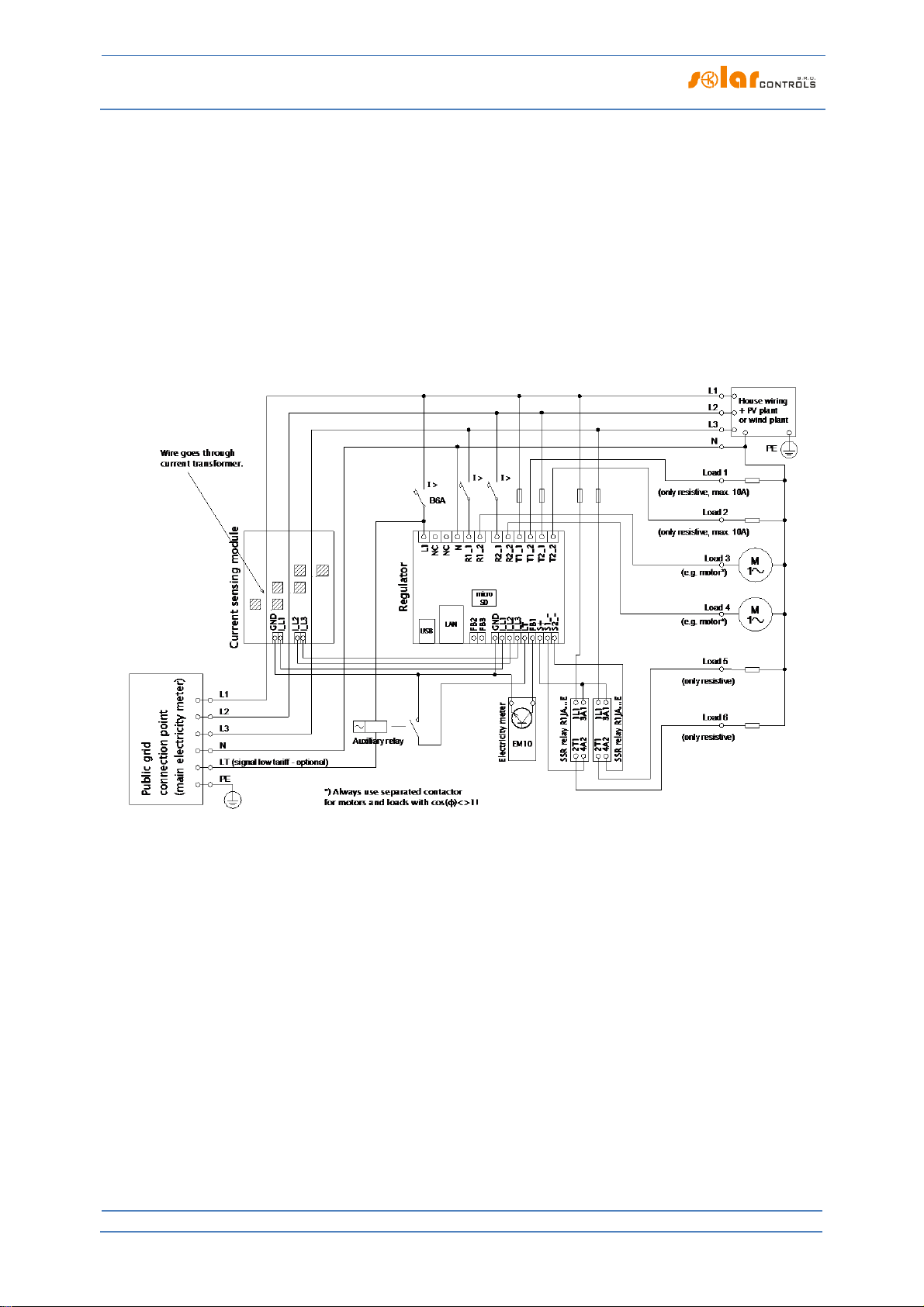
The current sensing module measures electric current in real time and on all phases. The regulator evaluates
the measured electric currents and if it determines the available surplus energy produced by the PV-plant, it
will switch on connected loads according to adjustable priorities, while constantly trying to maintain zero
energy flow through the current sensing module, the so called "virtual zero" (the sum of active power outputs
on all three phases = 0) or optionally, on each phase separately, so called "phase zero".
Switching according to priorities is done in the following way:
By default (during night), all loads are turned off. If surplus energy generated by PV-plant is determined in the
morning, the output with the first (highest) priority is switched on.
The switching time is different according to selected output function.
Triac/SSR/PWM outputs (proportional outputs) are switched on almost immediately after surplus
energy is detected and the controller is gradually (synchronous control or PWM modulation)
maintaining "virtual zero" or "phase zero", according to the control settings.
Relay outputs are switched on only if the surplus energy exceeds the preset load‘s nominal power.
Alternatively, relay outputs may be operated in "prepend" mode if there is sufficient power at any
proportional output with nearest higher priority. This allows for maximum utilization of the produced
surplus power even for relay outputs - refer to the "Prepend before triacs/SSRs" function.
When load with 1st priority is switched on (for proportional output it means switching on the maximum
power), the system waits until the power output of PV-plant increases again (beginning of dawn). If electric
production is determined even when this load is switched on, load with second priority in the same mode is
switched on as well.
If the power output of PV-plant is still increasing, additional connected loads are switched on in the same
mode.
If the power output of the PV-plant decreases, or if another load - not connected to the WATTrouter device is
switched on, the switched (active) outputs are disconnected - again according to preset priorities but in reverse
order (the load with lower priority is disconnected first).
For relay outputs there may be set a minimum switching time. If, simultaneously with a relay output the
proportional output with higher priority is switched on, and the available surplus energy is reduced, then this
proportional output will reduce the power output of the of the load (even down to zero) in order to maintain
virtual zero or phase zero on the current sensing module, if possible.
Except for the situation specified in the paragraph above, the controller never violates the established
priorities.
The above specified principle applies only to standard connection of the current sensing module, connected
right behind the facility’s main energy meter, so the WATTrouter device uses only the actual PV-plant surpluses
(recommended settings). However, WATTrouter controller is versatile device and can be connected according
to your needs. For example, you can place the current sensing module just next to the PV inverter and then you
can maintain the virtual or phase zero on that line.
The above specified basic control mode may be combined with another mode of output switching, provided
that low tariff signal (double tariff rate) is available (CombiWATT mode), or with switching based on preset time
conditions (time schedules).
This device is not designed for precise active power measurement (it is not a replacement for a
wattmeter or electricity meter). Active power is measured with sufficient precision in order to
maintain all control functions.

WATTrouter M - user manual
How to fit and setup the device
Page 6 from 79
PACKAGING CONTENTS
Contents of packaging:
1 WATTrouter M regulator
1 WATTrouter M current sensing module
1 USB cable
1 short manual with links to this manual, software and firmware updates.

WATTrouter M - user manual
How to fit and setup the device
Page 7 from 79
SAFETY WARNING
When you receive your package, inspect the packaging unit for damages. After opening
your package, inspect the regulator and the current sensing module for damages. Do not fit
the regulator or the current sensing module if you see signs of mechanical damages!
Always have the regulator and the current sensing module fitted by a person with the
necessary electrical qualification. It is necessary that you read this manual thoroughly and
observe all safety warnings and requirements specified herein.
The regulator and the current sensing module must be fitted in a dry room without
excessive dust level. The room must be protected from direct sunlight and the ambient
temperature must be maintained within the range mentioned in chapter Technical
specifications. Do not place the regulator or other electronic components of this system
near flammable objects!
When power SSRs are connected to SSR outputs or built-in triacs are used, it is absolutely
necessary to fit these into a distribution box equipped with adequate heat dissipation
system (with ventilation grid or vents)!
Make sure that unauthorized persons, mainly children, cannot access the location where
the controller is fitted. There is a serious risk of electric shock!
Only connect outputs of the controller to electrical loads which have been designed for this
operation mode and for which the manufacturer does not explicitly prohibit connection via
switching element!
The manufacturer is not liable for any damages occurred due to improper fitting or
operation of the device! The owner is fully responsible for operation of the entire system.

WATTrouter M - user manual
How to fit and setup the device
Page 8 from 79
FITTING THE DEVICE
WATTrouter M regulator may be fitted in a regular distribution board onto a 35 mm DIN rail or attached to a
wall using 2 screws with round or countersink head and with diameter up to 6 mm.
WATTrouter M current sensing module may be fitted in a regular distribution board onto a 35 mm DIN rail.
Measuring inputs of the current sensing module may be connected as single, double, or triple-phase
connections.
The recommended maximum distance of the current sensing module and the regulator is 2 meters. Bigger
distance is acceptable, but it will slightly affect the measuring accuracy.
If CYKY or other thick and hard cables cannot pass through current transformers easily, use flexible cables to
extend the existing connections. When fitting the current sensing module do not press hard on it. You may
damage the module.
Tip: Individual phase wires may pass through the current sensing module from either direction. The direction of
currents may be configured in the control software.
To connect power supply to the regulator (L1 and N) use wires with a minimum cross-section of 0.5 mm2, for
example CYKY 1.5.
To connect loads to the relay outputs use wires with adequate cross-section corresponding with the power
ratings of the connected loads.
To connect loads to the power triacs or SSRs again use wires with adequate cross-section corresponding with
the power ratings of the connected loads.
To interconnect the current sensing module and regulator (inputs GND and ILx) use 4-wire cable with cross-
section from 0.5 to 1.5 mm2. If these wires are longer than 2m or are placed in a cable tray together with other
power cables/wires, we recommend using a shielded cable.
To interconnect power SSR control inputs and/or PWM control signals with SSR outputs use wires with cross-
section from 0.5 to 1.5 mm2. If these wires are longer than 2m or are placed in a cable tray together with other
power cables/wires, we recommend using a shielded cable.
To interconnect S0 impulse signals from external energy meters with FB inputs use 2-wire cable with cross-
section from 0.5 to 1.5 mm2, connected between GND and respective FB terminal. If these wires are longer
than 2m or are placed in a cable tray together with other power cables/wires, we recommend using a shielded
cable.
Connect shielding of all shielded cables to the GND terminal as close as possible to the regulator.
Figure 1: Connector and LED description (top view). Connection is the same for the WATTrouter M MAX device.
Regulator terminals - description:

WATTrouter M - user manual
How to fit and setup the device
Page 9 from 79
Top left terminal block (this only accepts voltage from public grid!):
L1 –regulator power supply and voltage detection L1, 230VAC/50Hz (must always be connected)
N –neutral wire (must always be connected)
R1_1 –relay output 1 –terminal 1
R1_2 –relay output 1 –terminal 2
R2_1 –relay output 2 –terminal 1
R2_2 –relay output 2 –terminal 2
T1_1 –triac output 1 –anode A1
T1_2 –triac output 1 –anode A2
T2_1 –triac output 2 –anode A1
T2_2 –triac output 2 –anode A2
Left bottom terminal block
FB2 –input for connection of impulse output of external energy meter (0V or +5V)
FB3 –input for connection of impulse output of external energy meter (0V or +5V)
Right bottom terminal block
GND –common wire coming from the current sensing module (must always be connected)
I_L1 –electric current measuring input L1 from the current sensing module (must always be
connected)
I_L2 –electric current measuring input L2 from the current sensing module
I_L3 –electric current measuring input L3 from the current sensing module
LT –low tariff signal detection (0V or +5V)
FB1 –input for connection of impulse output of external energy meter (0V or +5V)
S+ –external SSR outputs –common positive electrode (+5V)
S1-–external output for SSR 1 –negative electrode (open collector)
S2-–external output for SSR 2 –negative electrode (open collector)
Left bottom communication connectors
USB –USB interface connector (USB B)
LAN –Ethernet interface connector (RJ45, 10/100 Mbit/s)
LED description:
PWR –regulator power on light (green)
USB –communication light - USB interface (yellow)
ERR –error status light (red)
T1 –triac output No. 1 - activity indication light
T2 –triac output No. 2 - activity indication light
R1–relay output No. 1 - activity indication light
R2–relay output No. 2 - activity indication light
S1–external output for SSR 1 - activity indication light
S2–external output for SSR 2 - activity indication light
RJ45 connector –Ethernet connection indication light (left green LED –carrier frequency, right green
LED - connection speed)
GND I_L1 I_L2 I_L3

WATTrouter M - user manual
How to fit and setup the device
Page 10 from 79
Figure 2: Connection terminals of current sensing module WT 02/10 for WATTrouter M SSR and WT 03/11 for WATTrouter M
MAX.
Current sensing module terminal description (the terminals are described directly on the motherboard of the
M MAX module):
GND –common wire (must always be connected)
I_L1 –current measuring output L1 (must be always connected)
I_L2 –current measuring output L2
I_L3 –current measuring output L3
Connect the controller according to sample connection diagrams shown on figures below. If you observe basic
principles, connections may be combined in various ways. You may connect any number of loads to any
outputs; in certain cases you may remove certain phase cable from the measuring, etc.
Figure 3: Three-phase connection with low tariff signal circuit for CombiWATT mode. Current sensing module is placed at the facility’s
supply cable coming from the distribution box where main energy meter is located. The connected loads use only real surpluses
produced by PV-plant. All 6 loads are connected, 2 of them through the recommended SSR, line RJ1A - manufactured by Carlo Gavazzi.
One energy meter type EM10 manufactured by Carlo Gavazzi with pulse output (open collector) is connected to input FB1. The electric
meter can measure any flow of energy, for example net production of the PV-plant.

WATTrouter M - user manual
How to fit and setup the device
Page 11 from 79
Figure 4: Three-phase connection with 2 current sensing modules and with low tariff signal circuit for CombiWATT mode. This
connection is necessary if the PV-plant output is connected directly to a sealed distribution box, accessible only to the electricity
provider. This may be the case for PV-plants made originally only for feed-in tariff, without self-consumption possibility. Current sensing
module 1 is connected to the household wiring branch; current sensing module 2 is connected to PV-plant branch. The accuracy of
measurement is reduced down to ± 10% in this connection because of the finite impedance of current transformer secondary winding.
Caution: Current flow through current sensing modules must always be subtracted in this connection (marked with arrows on the
picture). The same phase sequence must be observed in the regulator and in both current sensing modules!
Figure 5: Three-phase connection of WATTrouter M with 2 regulators and without low tariff signal circuit (CombiWATT mode cannot be
used). Connection of other models is similar. Using this connection you may extend the number of outputs up to 12. Current sensing
module is placed at the facility’s supply cable coming from the distribution box where main energy meter is located. Connected loads

WATTrouter M - user manual
How to fit and setup the device
Page 12 from 79
use only the actual surpluses produced by PV-plant. To make things simple, only 3 resistive (heating) loads are connected, but you may
use all 12 outputs. Similarly, you may also connect 3 regulators to 1 current sensing module. In such scenario, each regulator works on
one phase and you will get 18 outputs.
Figure 6: Solid state connection of the entire RGS1A line, manufactured by Carlo Gavazzi. Relays RGS1A are replacements for older
types R1JA. You may also use other SSR with similar parameters (see chapter Technical specifications).
Figure 7: Increasing of current measurement range of the device for facilities where main circuit breaker is larger than 3x125A.
Transformers 200/5A, or even 400/5A may be used, based on the main circuit breaker value. Secondary coil of current transformers is
shorted through the current sensing module (the secondary circuit passes through measuring transformers in the current sensing
module). Increasing of current measurement range may be done in both SSR and MAX models, but we recommend WATTrouter M SSR
model due to higher resolution of A/D converter when current transformers with nominal secondary current of 5A are used. Additional
increase of current measurement range may be done if you take the secondary circuit of the current transformer and make several turns
through the measuring transformer in the current sensing module (for transformers 200/5A, the best option is to make 4 turns in order
to reach optimum transfer ratio 200/20A). For this purpose we recommend using lines, which are not overrated for the nominal
secondary current, just to be able to make more turns through the hole of measuring transformer. When connected through external
current transformers, the conversion ratio must be set correctly in the control software - see the item Conversion ratio of external CT‘s
in the main window of the WATTconfig M software.
Load
(only resistive)
L1
T1
A1+ A2-
RGS1A23D..
L1
N
to current sensing module
I >
Regulator
I_L1
I_L2
I_L3
FB2
FB3
GND
S2_-
S+
S1_-
FB1
R2_1
R2_2
L1
N
NC
LT T1_1
T1_2
T2_1
T2_2
R1_1
R1_2
NC
USB
LAN
micro
SD

WATTrouter M - user manual
How to fit and setup the device
Page 13 from 79
Figure 8: Single-phase connection with optional low tariff signal circuit for CombiWATT mode. Current sensing module is placed at the
facility’s supply cable coming from the distribution box where main energy meter is located. The connected loads use only real surpluses
produced by PV-plant. All 6 loads are connected, 2 of them through the recommended SSR, line RJ1A - manufactured by Carlo Gavazzi
(now superseded by RGS1A or RGC1A series). One optional energy meter type EM10 manufactured by Carlo Gavazzi with pulse output
(open collector) is connected to input FB1. The electric meter can measure any flow of energy, for example net production of the PV-
plant.
The controller may be connected only to 230VAC, 50 Hz public electric grids.
Regulator must be protected with a circuit breaker - recommended rating is B6A -
and connected loads must also be adequately protected! Installation may only be
done when the facility’s main circuit breaker is turned off!
Upon completion of the installation process make sure to check thoroughly the connection of the
regulator and the current sensing module. Also check connection of all terminals at the bottom,
where NO power grid voltage or voltage outside of tolerances specified in the chapter Technical
specifications may be connected! NO other than resistive (heating) loads may be connected to
built-in triacs or power SSRs! Regular relays CANNOT be connected to SSR outputs! It is
prohibited to connect loads with higher than the maximum allowed nominal power! If you fail to
observe these rules it is almost guaranteed that you will damage the regulator and lose your
warranty!
For the correct operation of the controller, it is absolutely necessary to ensure proper phasing of
the measured currents with the internal voltage detector. This can be done by selecting the
appropriate phase in the Input Settings tab. It is strongly recommended to connect the controller
so that the phase conductor fed to terminal L1 corresponds to the phase conductor
wired through the measuring transformer corresponding to the IL1 input, which
will allow the measurement to match the default settings of the controller (and

WATTrouter M - user manual
How to fit and setup the device
Page 14 from 79
therefore the same as required for older models or older firmware versions). The IL2 and IL3
current inputs can be connected arbitrarily, the respective phases for these inputs must be set up
correctly in the WATTconfig control software.
We strongly advise you to protect your loads connected to the built-in triacs or power SSRs with
fuses suitable for protection of semiconductors, rather than regular circuit breakers. Please note
that SSRs damaged by overcurrent or short-circuit most likely cannot be claimed under warranty.
Make sure that solid state relays are correctly connected, as required by their user manual.
No electronic devices (various measuring and protective elements, such as sub-meters and
residual current circuit breakers) may be installed between the SSRs and the appliance, since
they may be damaged by impulse power! Always install these devices on the line between the
fuse and the solid-state relay where constant power is available.
If your facility is located in an area with higher risk of overvoltage spikes due to atmospheric
discharge (lightning), we strongly recommend fitting a suitable overvoltage/lightning protection
between the distribution box with the main energy meter and the current sensing module!
The current sensing module supplied with the WATTrouter M SSR controller is fully compatible
with the current sensing module supplied with older types, such as WATTrouter CWx,
WATTrouter CWx SSR and vice versa. The current sensing module installed with these controllers
can be used with the WATTrouter M controller (and vice versa)
If your computer is connected via USB cable ALWAYS USE ONLY ONE USB port on the regulator. If
you fail to do so, you may damage the USB interface of the regulator.
If the regulator is constantly connected to PC via USB interface (mostly if long cable is used), we
strongly recommend using an USB isolator!
Note: It is allowed to connect only pure resistive loads to triacs and power SSRs. These loads cannot be fitted
with own electronic control system nor with built-in motors (e.g. fans - see the note below). These loads may
only have regular mechanically controlled thermostats and indication LEDs or neon lamps. Almost any regularly
produced boilers, immersion heaters, infra radiators, heating floor pads, motor-free dryers (infra dryer), oil
heaters, cartridge heaters in a solar tanks, etc. may be used.
Note: Each triac or SSR output is capable of providing power to heating loads with built-in fan for longer time
(such as hair dryer, heat radiator). These loads are fitted with a built-in thermal protection, which, if
synchronous triac or SSR control mode is used for that load, will disconnect the load for low power of triac/SSR
output (in this scenario, the built-in fan’s power is not sufficient to cool down the heating element of the load).
Therefore, consider fitting these loads to triac/SSR outputs carefully.
Note: Heating loads connected via residual-current circuit breaker may be connected to triac/SSR outputs.
Note: Heating loads with nominal power up to 2 kW may be connected to relay outputs directly, without using
external contactor.
Carefully examine connection of the controller and then turn off all circuit breakers and deactivate fuse
switches for connected loads. Then turn on the main circuit breaker and the regulator circuit breaker (L1 power
supply). The LED PWR lights up (power on indication). If the light is off, or if it does not shine permanently, or if
the LED ERR starts to flash (error status), proceed according to instructions specified in the Troubleshooting
chapter. In default status no output is active and therefore, no load will be turned on.

WATTrouter M - user manual
How to fit and setup the device
Page 15 from 79
Now the controller is fitted and ready for configuration.

WATTrouter M - user manual
How to fit and setup the device
Page 16 from 79
DEVICE CONFIGURATION
You will need notebook or regular PC (placed closely enough to the regulator) with USB interface (hereinafter
referred to as a computer only). The controller is configured using the WATTconfig M control software. The
installation package for this software is available on manufacturer’s web pages. Before installing the
WATTconfig M control software you need to install the driver for USB interface.
In order to connect to the USB interface using the USB port accessible from the top of the device,
turn off the regulator circuit breaker and remove the semi-transparent regulator cover. If you
want to connect using the USB port accessible from the bottom side, it is necessary - due to
safety reasons - to turn off the entire distribution box before manipulation.
Tip: After you configure Ethernet network connection you may perform all settings including firmware update
over the Ethernet interface. You do not need to use the USB interface at all, provided that the parameters of the
connected LAN are the same as the default controller parameters (see below), and if there is no conflict
between IP addresses or conflict between physical MAC addresses.
If you cannot continue with the settings (due to any reasons), proceed according to instructions specified in the
Troubleshooting chapter.
USB DRIVER INSTALLATION
The installation procedure is described for Windows XP, English locale. The procedure is similar for newer
systems, or it is much simpler. Newer operating systems (Windows, Linux, MAC OS) usually have these drivers
pre-installed, hence you can skip following sections.
1. Insert the attached USB cable to the USB connector of the regulator and then to the computer.
2. Turn on the controller. The green LED PWR must light up (power on indication). Also the yellow LED
USB light will or should flash briefly (communication process indication) as the USB device will start to
register in your computer.
3. After a moment, following window must appear confirming that a new device was found:

WATTrouter M - user manual
How to fit and setup the device
Page 17 from 79
4. Select: No, not this time. In the following window select: Install from a list or specific location
(Advanced).
5. Select the path to the driver file:

WATTrouter M - user manual
How to fit and setup the device
Page 18 from 79
6. The driver has been installed successfully, if this window appears:
7. During the installation there might appear a warning about an invalid digital driver signature. Just
ignore it. The device is registered in your system device manager as USB serial converter (menu
Universal Serial Bus Controllers)
8. You must perform the same installation process for the second USB serial port device.
WATTCONFIG M CONTROL SOFTWARE INSTALLATION

WATTrouter M - user manual
How to fit and setup the device
Page 19 from 79
1. Turn on the PC.
2. Run WATTconfig_M_Setup_x86_64.exe.
3. Follow the on-screen instructions.
SETTING UP MAIN FUNCTION
1. Click on START button in your PC and run the WATTconfig M control software. The system will display
the main software window.
2. Make sure that the controller is turned on and connected to your computer. Make sure that USB
interface driver is correctly installed.
3. Select USB interface connection mode (field next to the "Connect" button).
4. Select correct port for connection. This can be done in the dropdown menu Port in USB/COM driver
configuration window, which will show up by clicking on button Configure connection.
Note: Unlike WATTrouter CWx devices or older firmware versions the WATTrouter M uses a serial port
connection (COMx). This port is always virtual port because the controller is connected via USB. Once more
ports are displayed, it is necessary to check in Windows device manager, which port is assigned to USB
Serial Port.
5. Click the "Connect" button. The controller should be now connected and the connection indicator (a
stripe) should be displayed in green. If it is not, and the system displays an error message, wait until
the USB driver is ready for use in your PC, or inspect the settings in the USB driver configuration
window. You may display the window by pressing the Configure button.
6. After establishing successful communication, you should be able to see the current measured values
(power outputs on individual phases, etc.). No outputs should be active ("unused" priority). Also no
time schedules should be used.
7. Now you can configure measuring inputs. This can be done on the "Input settings" tab. First, you set
the phase sequence and then the direction of current flows through the current sensing module.
a. Setting up phase sequence: Turn off the PV-plant and turn on a resistive load on each phase
which will be involved in the measuring process. The system will display measured active
power on each individual phase. For now, you may ignore the signs of the measured power
values. Now, in the Phase field select corresponding phase, based on the actual status
recognized by the controller, and press Write button. The configuration will be saved in the
controller. If the output values measured on individual phases differ too much from the
reality, change the phase for given input and again press the Write button. Repeat these
steps for all 3 inputs IL1, IL2 and IL3 until all measured powers are displayed correctly.
b. Setting up the direction of current flows through the current sensing module: As specified in
the previous steps, leave loads on measured phases switched on. When the PV-plant is
turned off, all measured power output values must be smaller than 0 or equal to 0. If any of
the measured power outputs is positive it means that the phase wire is passing through the
current sensing module in a reverse direction. Use the Current orientation field for the
relevant phase, select the reversed option and press the Write button. The configuration will
be saved in the controller. Now, all measured power outputs must be <= 0. Turn the PV-plant
on and turn off all loads. Now, measured outputs must be positive (>=0). If they are not, or if
the measured values do not correspond with nominal power ratings of the connected loads,
or if they do not correspond with the power output of the PV-plant, you have either still
connected another loads (which you don‘t know about, such as various loads in stand-by

WATTrouter M - user manual
How to fit and setup the device
Page 20 from 79
mode, etc.), or the phase sequence in voltage or in current inputs does not match, or you may
have a defect in household wiring. In any case, make sure to inspect the entire electric
wiring.
c. You can verify the correctness of measurement input configuration by using the chart "Input
checking oscilloscope". This chart shows measured current waveforms in selected phase,
values are given in units of the built-in A/D-converter (digits), these are not normalized to
amps due to performance. This feature should only aid the fitter when configuring the
measuring inputs. Always verify with a resistive (heat) load only, so that the phase shift
between voltage and current is zero (𝒄𝒐𝒔(𝝋)= 𝟏)! Moreover, in order to verify the
measuring inputs the amplitude of current half-wave should always be greater than 1000
digits (to be sure about the correctness of the settings).
Note: During normal operation there may be shown even "exotic" waveforms. Be sure this is
the real current flowing through the phase wire, a superposition of currents flowing through
the connected appliances which are not always sinusoidal or their power factor varies from
one.
Figure9: Input is fitted correctly - sine wave of the current flowing through a resistive (heat) load is in phase with the voltage.
WATTconfig shows negative values on selected phase (consumption). Left image appears when there is normal (default) current flow
direction, right image appears for opposite direction. Note: The PV-inverter throughput appears exactly as the opposite, because the
current is anti-phased with the voltage. If the inverter performs power factor compensation you can observe corresponding phase
shifts.
Figure 10: Input is fitted incorrectly - sine wave of the current flowing through a resistive (heat) load is not in phase with the voltage and
either precedes (image left) or lags behind (image right) the voltage by 1/3 of mains half-wave. Measuring inputs are fitted incorrectly
and you need to select correct option in the Phase field for respective input.
8. After a successful setup of measuring inputs you may begin to test outputs. This can be done on the
"Output settings" tab. Each connected load must be tested separately. Turn on circuit breaker or
activate fuse switch for the first output, and press the TEST button for the corresponding output. The
load should switch on. When you switch on triac output, the built-in fan in the regulator is
automatically turned on. Further, when the load is switched on, the active power drawn by connected
load must be detected by the current sensing module on the relevant phase.
9. After you have successfully tested all outputs, you may begin to configure the control mode in the
Control settings field. This can be done on the "Other settings" tab. Set this mode either to "sum of all
phases" or to "each phase independently", based on the configuration of your 4-quadrant energy
meter. If you are not sure how your energy meter is configured, please contact your electricity
This manual suits for next models
10
Table of contents
Other Solar Test Equipment manuals
Popular Test Equipment manuals by other brands

Alcohol Countermeasure Systems
Alcohol Countermeasure Systems DRIVESAFE instruction manual

multicomp pro
multicomp pro MP740890 user manual

Precision
Precision 660 operating instructions

urmet domus
urmet domus 3000 quick guide

Seaward
Seaward PrimeTest 300 Quick reference guide

Mastech
Mastech MS5902RTB instructions