CPS AC-PLC KIT-800V/US User manual

Installation and Operation Manual
for CPS AC-PLC KIT-800V/US
CHINT POWER SYSTEMS AMERICA CO., LTD.
Rev 1.1 Apr. 14, 2022 Doc. No.: 9.0020.0629A0

Table of Contents
2 / 32
Table of Contents
0Preface .............................................................................................. 4
1IMPORTANT SAFETY PRECAUTIONS ........................................... 5
Symbols and meanings in this document ......................................................5
Markings and meanings on the device ..........................................................5
Safety precautions of operating the AC-PLC KIT ..........................................6
2General Introduction........................................................................ 8
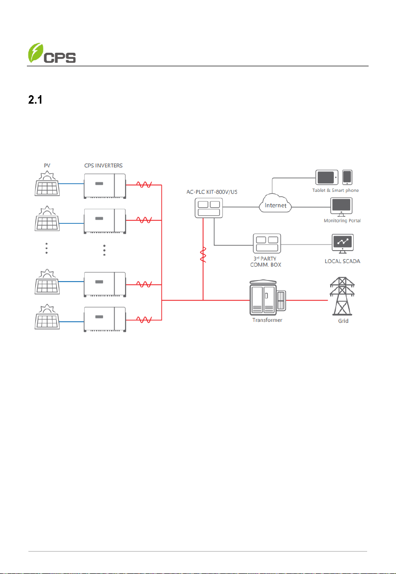
Overview of AC-PLC KIT-800V/US................................................................8
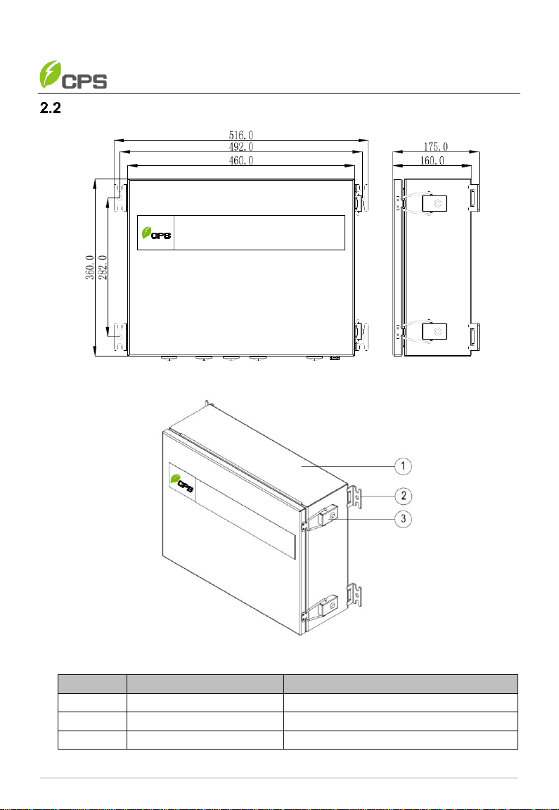
Appearance and dimension...........................................................................9
Features of AC-PLC KIT..............................................................................10
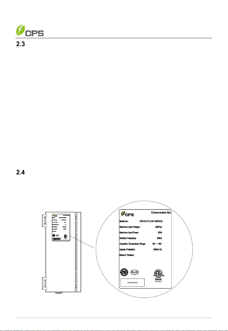
Nameplate ...................................................................................................10
Storage requirements..................................................................................11
Schematic Diagram and Circuit Design.......................................................11
3Mechanical Installation ................................................................. 12
Unpacking for Inspection .............................................................................12
Installation requirements .............................................................................12
3.2.1 Environment requirements ..................................................................12
3.2.2 Installation requirements .....................................................................13
Installation procedures ................................................................................13
4Electrical Connection .................................................................... 16
External Connection interfaces....................................................................16
Internal wiring terminals...............................................................................17
4.2.1 Appearance of PLC module ................................................................18
4.2.2 Indicator description............................................................................19
Recommended tools and torque .................................................................19
Cable connection.........................................................................................19
4.4.1 Copper bar grounding .........................................................................21
4.4.2 RS485 Communication Terminal Connection......................................21
4.4.3 Antenna Connection ...........................................................................21
4.4.4 AC Input Power Connection................................................................21
Cable Connection Notices for Joints and Seals...........................................21
5Commissioning and Maintenance ............................................... 25
Commissioning............................................................................................25
5.1.1 Inspection before Commissioning .......................................................25

Table of Contents
3 / 32
5.1.2 Commissioning steps..........................................................................25
Regular Maintenance ..................................................................................25
6Troubleshooting............................................................................. 26
Power-on faults ...........................................................................................26
Communication faults..................................................................................26
Data collection failures ................................................................................27
7Technical Data................................................................................ 28
8Limited Warranty............................................................................ 30
Warranty period ...........................................................................................30
9Contact Information....................................................................... 31
10 Appendix......................................................................................... 32
Appendix A: Figure list.................................................................................32
Appendix B: Table list ..................................................................................32

Preface
4 / 32
0 Preface
Thank you for choosing CPS AC-PLC KIT-800V/US (hereinafter referred to as "AC-
PLC KIT") developed by CHINT POWER SYSTEMS AMERICA CO., LTD (hereinafter
referred to as "CPS").
IMPORTANT!
Please read this manual carefully and make sure that you have
understood all the contents thoroughly before you start any operation.
Main Contents
Safety precautions, device overview, installation, operation and maintenance,
technical data as well as quality assurance are mainly introduced in this manual.
Target Reader
This manual is applicable to the work staff of wiring, installation, maintenance and daily
management of the AC-PLC KIT.
Manual Management
Please store this manual together with related documents of other device components,
and make sure keep it at hand for quick reference and easy use.
Copyrights
CPS reserves all rights in this manual. Any reproduction, disclosure or copy in whole
or in part is forbidden without prior written authorization. CPS doesn’t accept any
responsibilities whatsoever for potential errors or possible lack of information in this
document.
Version
This manual is subject to technical change or contents modification without prior notice.
The actually purchased device shall prevail. Users can get the latest manual from our
sales channel or our official website: www.chintpowersystems.com.

IMPORTANT SAFETY PRECAUTIONS
5 / 32
1 IMPORTANT SAFETY PRECAUTIONS
Please read this user manual carefully before the installation and operation of this AC-
PLC KIT. CPS reserves the right to refuse warranty claims for equipment damage if
users fail to install the equipment according to the instructions in this manual.
Symbols and meanings in this document
Markings and meanings on the device
Symbol
Meanings
HIGH VOLTAGE!
Danger to life due to high voltage!
All work on the device must only be performed by qualified personal as
described in this document.
HOT!
The equipment is designed according to international safety standards,
but surfaces can become hot during operation. DO NOT touch the
peripheral surfaces during or shortly after operation.
Symbol
Meanings
DANGER!
DANGER indicates a hazardous situation with high level of risk which, if not
avoided, will result in death or serious injury.
WARNING!
WARNING indicates a hazardous situation with medium level of risk which,
if not avoided, could result in death or serious injury.
CAUTION!
CAUTION indicates a hazardous situation with low level of risk which, if not
avoided, could result in minor or moderate injury.
NOTICE!
NOTICE indicates a hazardous situation which, if not avoided, could result
in equipment working abnormally or property loss.
IMPORTANT!
IMPORTANT indicates important supplementary information or provides
skills or tips that can be used to help you solve a problem or save you time.

IMPORTANT SAFETY PRECAUTIONS
6 / 32
EARTH GROUND!
This symbol marks the location of grounding terminal, which must be
securely connected to the earth through the PE (protective earth) cable
to ensure operational safety.
RoHS SYMBOL
In accordance with 2011/65/EU regulations, the product imposes
restrictions on the use of specific hazardous substances in electrical and
electronic equipment.
ETL Certification
This product has passed certification of ETL organization.
Safety precautions of operating the AC-PLC KIT
Symbol
Meanings
DANGER!
Touching the wiring terminals inside the device may result in death by
electric shock!
DO NOT touch the terminals or conductors connected with PV
modules or PV inverters, which may result in death by electric shock!
WARNING!
All the installation and wiring connections should be performed only by
qualified technical personnel.
Make sure both the AC and DC sources are disconnected, and the
shell of device is securely grounded to avoid electric shock during
maintenance or installation.
DO NOT touch live or exposed parts of the input and output sides to
avoid electric shock when checking or maintaining the device.
CAUTION!
Handle the AC-PLC KIT carefully to prevent falling off due to its weight.
Check the device and make sure there is no problem with the
installation before putting it into operation.
Connect the wires of the device to avoid short circuit hazard, to ensure
personal safety and the normal operation of the device.
Although the AC-PLC KIT is certified to international safety standards,
it will become hot during operation. DO NOT touch the hot parts of the
device during operation.
NOTICE!
Follow all the wiring and safety instructions of the AC-PLC KIT.

IMPORTANT SAFETY PRECAUTIONS
7 / 32
All the wiring and operation must conform to the related local standard
requirements of the device.
IMPORTANT!
The device nameplate contains important information of the device,
such as model, serial number and detailed parameters.
If there is any problem or malfunction of the device during operation,
please contact our after-sales center and provide the serial number.
Our service personnel can provide timely service for you.
Please keep the nameplate intact.

General Introduction
8 / 32
2 General Introduction
Overview of AC-PLC KIT-800V/US
The AC-PLC KIT is widely applied in residential electricity information
collection, photovoltaic, smart home, industrial control and other fields.
The Grid-tied PV system is generally made up of PV modules, string PV
inverters, AC-PLC system, etc. as shown below.
Figure 2-1 The diagram of Grid-tied PV system
The AC-PLC KIT includes an outdoor cabinet, with RS485 signal lightning
arrester, PLC master module, intelligent communication gateway and relevant
power supplies and overcurrent protection devices. Together, they implement
and achieve the communication control function of the PV power station arrays,
collect the operating data of the inverters and other equipment in the system and
upload it to the remote monitoring system. Via the remote monitoring system,
users can access the WEB interface to view operation information and set
parameters.

General Introduction
9 / 32
Appearance and dimension
Figure 2-2 Product Dimensions
Figure 2-3 Product Appearance
Item No.
Component Name
Marks
1
Main enclosure
Main body
2
Fixing bracket
Install enclosure to wall or bracket
3
Lock (with keys)
Lock the enclosure
Table 2-1 Component Name

General Introduction
10 / 32
Features of AC-PLC KIT
Safe and reliable
- NEMA 4X rated enclosures for exterior mounting
- Enclosure made of DC51D+ZM180 with high corrosion resistance
Compatibility
- Compatible with CPS 250/275kW inverters
- Capability with CPS O&M platform
Powerful protection performance
- Equipped with high-current, high-breaking and high-voltage AC fuse
- It is also possible to lock with keys to protect from accidentally turning
on
Convenient installation and maintenance
- Preconfigured for plug-and-play
- Hardware mounted and pre-wired
- Mounting brackets included
- No locking screws are required
- Convenient cable connections and maintenance
Nameplate
The nameplate contains important information of the device, such as model number,
serial number and electrical parameters, certification information, etc.
You can find the nameplate on the right side of its enclosure, as shown below.
Figure 2-4 Nameplate

General Introduction
11 / 32
IMPORTANT!
If there is any problem or malfunction of the device during operation,
you can contact after-sales service center and provide the device serial
number.
Our service personnel can find out the date of production and other
necessary information quickly and provide service for you. Therefore,
please keep the nameplate complete and intact.
Storage requirements
Close the front door tightly to avoid from opening accidentally.
Storage space shall be clean and dried and be free from dust or moisture.
The temperature of the storage space shall be kept between -25℃ and +70℃
as shown below.
The relative humidity of the storage space shall be kept between 5% and
95%.
Schematic Diagram and Circuit Design
The basic electrical schematic diagram of CPS AC-PLC KIT-800V/US is shown in
Figure 2-5 below.
Figure 2-5 schematic diagram of CPS AC-PLC KIT-800V/US
The transformer low voltage side inputs shall be connected to the fuses in the AC-PLC
Kit. The fuses shall then be connected to the Power Line Communication (PLC)
transmitter, which can transfer the PLC signal to Modbus-RTU through which the signal
can be further sent to the FlexOM Gateway. Meanwhile, the transformer in the AC-PLC
Kit provides 110Vac and an AC-DC power supply provides 12Vdc to power the PLC
transmitter and FlexOM Gateway.

Mechanical Installation
12 / 32
3 Mechanical Installation
Unpacking for Inspection
Check the product for any obvious damage or if the items in the delivery list are
complete before performing installation. Contact CPS immediately if any problem is
found.
The delivery list of the AC-PLC KIT is below:
No.
Images
Accessories
QTY (pcs)
1
AC-PLC KIT
1
2
Fixing bracket
4
3
M6x14 screw
8
4
M8x25 screw
4
5
M8 Flange nut
4
6
Set of door keys
1
7
One manual and one warranty card,
one certification
3
Table 3-1 Delivery list
Installation requirements
3.2.1 Environment requirements
Inflammable and explosive materials inside and around the device are
strictly prohibited.
Good ventilation around the equipment shall be kept.
Ambient temperature range: -25°C ~ +60°C.
Ambient humidity range:≤95%, non-condensing.
High altitude:≤4000m.

Mechanical Installation
13 / 32
3.2.2 Installation requirements
Make sure the device is not electrically connected or energized before
installing.
Never install, use or maintain the device in lightning, rain, snow, wind and
other severe weather.
Do not wear conductive objects such as watches, bracelets, rings, and
necklaces when installing, operating, or maintaining the device.
After installing the equipment, remove empty packing materials such as
cartons, foams, plastics, and cable ties.
Paint scratches on the cabinet body caused in the process of transportation
and installation must be repaired. It is strictly prohibited to expose scratched
parts to the outdoor environment for long periods of time.
Installation procedures
The AC-PLC KIT can be installed on a wall or rack. Since the installation procedures
are similar, rack installation procedures are shown in this manual for reference.
WARNING!
All the installation and wiring connections should be performed by qualified
technical personnel only.
CAUTION!
Heavy device, move it carefully to avoid falling.
The installation procedures and installation illustrations are as follows:
1. Fasten four fixing brackets (2) into the pre-drilled mounting holes on the
backside of the enclosure (1) with eight M6X14 screws(3)in sequence.
Tool: 10# socket wrench, torque value:6 Nm.

Mechanical Installation
14 / 32
Figure 3-1 Position one fixed bracket
2. Mark mounting holes on the mounting bracket according to the distance of
the fixing brackets of the enclosure.
Figure 3-2 Distance of the fixing brackets of the enclosure

Mechanical Installation
15 / 32
3. Drill four holes with a Ф10mm drill at the marked position as shown below.
Figure 3-3 Drill holes at the marked position
4. Lift the AC-PLC KIT to make it aligned with above mentioned drilled holes
and fasten four fixing bracket (2) of the enclosure into the drilled holes of the
mounting bracket (3) with four M8x25 screws (1) and M8 flange nuts included
in the accessory bag.
Tools required: 14# socket wrench, torque: 12.5N.m.
Figure 3-4 Fasten fixing bracket of the enclosure into drilled holes
WARNING!
The installation surface shall be kept smooth and flat whether it is installed
on a wall or rack. Otherwise, the enclosure may be deformed or damaged,
thus developing a risk of water entering the product.

Electrical Connection
16 / 32 Doc. No.: 9.0020.0589B0
4 Electrical Connection
WARNING!
Be careful of high AC voltage. Check all the input and output cables or
terminals to ensure there is no voltage before electrical connection to avoid
electric shock.
CAUTION!
Connect the cables following strictly the polarities marked on the device to
avoid short circuit hazards.
External Connection interfaces
Before connecting cables, please note the external connection interfaces on the
bottom of enclosure, as shown below.
Figure 4-1 External connection interfaces
Item No.
Name
Meanings
1
AC
AC power input interface
2
Antenna
Wireless antenna output interface
3
COM1
RS485 bus signal access for AC-PLC
4
COM2
RS485 bus signal access for third party or other devices
5
Ground cable inlet
6
/
Vent valve
Table 4-1 External connection interfaces

Electrical Connection
17 / 32
Internal wiring terminals
Before connecting cables, please note the internal wiring terminals inside the
enclosure, as shown below.
Figure 4-2 Internal wiring terminals
NOTICE!
The stoppers reserved in items 1-5 are designed with a protection
class of IP65. They will be delivered with the AC-PLC product.
Engineers shall unplug corresponding stoppers before connecting
cables according to the project demands.
Reserve unused stoppers in their original positions to maintain the
protection class of the enclosure.

Electrical Connection
18 / 32
No.
Name
Specifications
1
Transformer
ES-10060.861
AC800,600,480V/AC110V 60VA
2
SPD
PE760-25M2-31
3
AC-DC Power
HDR-30-12
4
AC Receptacle
VGF15 125V
5
Fuse
HC101D 1000V 30A
HC10aR16UO 16A
6
Intelligent gateway
FlexOM 4G KIT CPS US.
7
PLC module
PLC-M/800Vac 12Vdc
8
Communication terminal
303901
9
Ground copper bar
/
Table 4-2 Main components in enclosure
4.2.1 Appearance of PLC module
The appearance of the PLC-M and PLC-S modules are exactly the same except for
the label. The PLC-S module is described in this section.
Figure 4-3 Appearance of PLC module
No.
Name
1
Inverters connect pins
2
Fixing holes
3
Indicators
4
AC terminal
Table 4-3 Components of PLC module

Electrical Connection
19 / 32
4.2.2 Indicator description
Icon
indicator name
Color
Function
PWR
Power indicator
Green
Flashes after power-on, flashing interval is
1s, and flashing time is 100ms.
PLC
Communication
indicator
Red
Flashes after PLC networking is
completed, the interval is 1s, and the
flashing mode is alternately on and off.
TX
RS485 port
sending indicator
Green
Flashes when sending data.
RX
RS485 port
receiving indicator
Red
Flashes when data is received.
Table 4-4 Indicator description
Recommended tools and torque
Name
Cable specifications
Tool
Torques
AC Input
#14AWG
Screwdriver
2.8N·m
Antenna
Comes with device
0.5N·m ~ 0.6 N·m
COM1/COM2
shielded cables
0.5N·m ~ 0.6 N·m
Grounding
#6AWG
2±0.2 N·m
Table 4-5 Recommended tools
Cable connection
WARNING!
This device is designed as a communication product, only qualified
personnel who are granted relevant access can implement the installation,
wiring, operation and maintenance work.
Please open the front door of the main enclosure according to the following steps
described below.
1. Insert your keys into the lock hole (3) and turn it to the ON position.
2. Pull the lock handle (1) outward till separating it from the lock bar (2).

Electrical Connection
20 / 32
Figure 4-4 open the front door
Now you can connect cables according to the following wiring illustrations.
WARNING!
Before wiring, ensure that upstream AC switches are all disconnected.
Figure 4-5 Wiring illustrations
Table of contents
Other CPS Test Equipment manuals

CPS
CPS Pro-Set TR21C User manual

CPS
CPS BlackMax TR700 Series User manual

CPS
CPS Pro-Set TR600 Series User manual

CPS
CPS CR500 Series User manual

CPS
CPS Pro-Set TR600A Series User manual

CPS
CPS Pro-Set TRA21 Series User manual

CPS
CPS BlackMax TR700C User manual

CPS
CPS AR2700 Series User manual

CPS
CPS FA1000 SERIES User manual