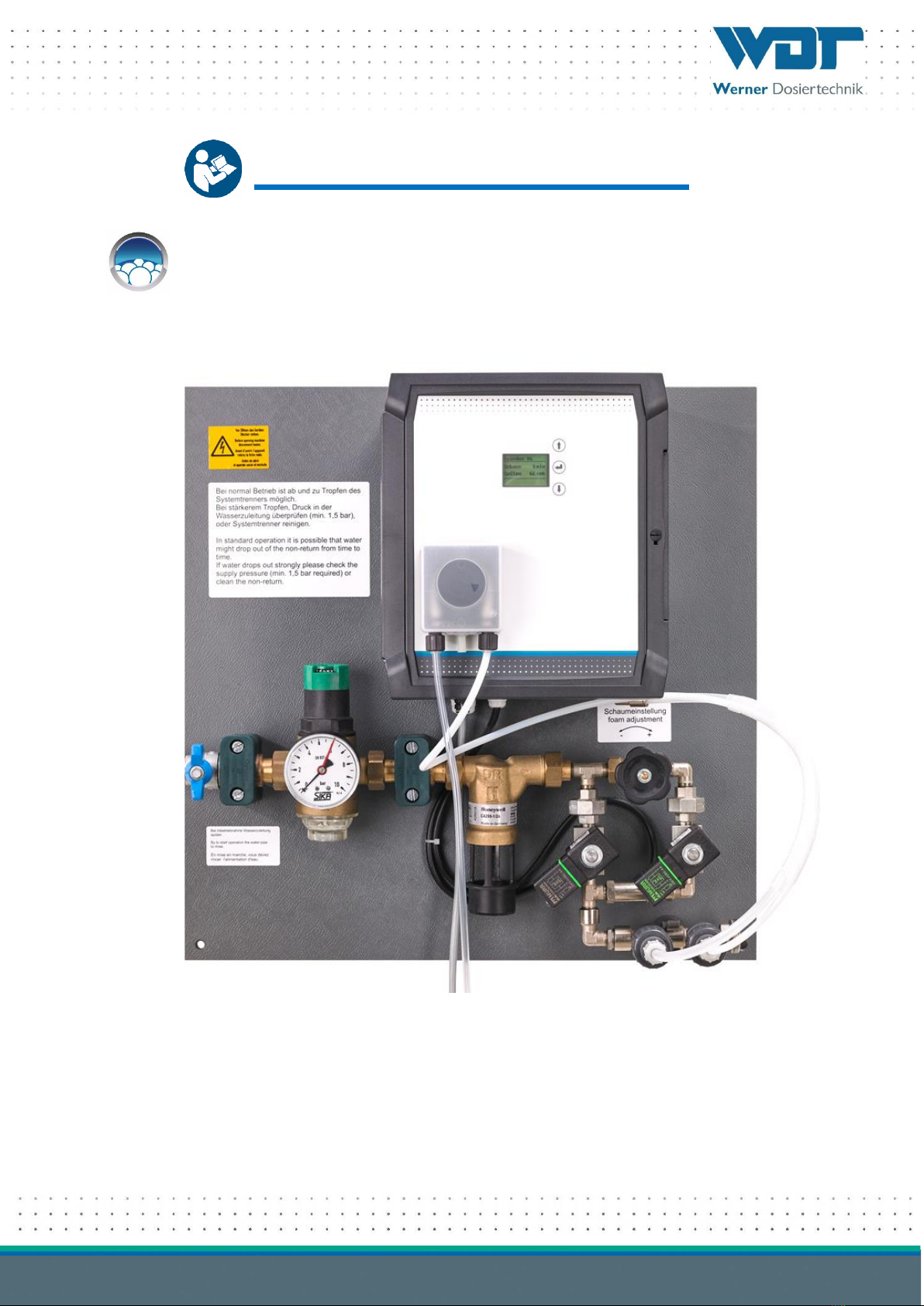
Dosing Device Foamdos V6
Index: 00 Date modified: 18/05/2021 OI No.: BA DW 025-00 Foamdos V6 EN.DOCX Page 2 of 37
Table of contents
1About these instructions / general...........................................................................................................4
1.1 Scope of applicability...................................................................................................................................4
1.2 Target group...............................................................................................................................................4
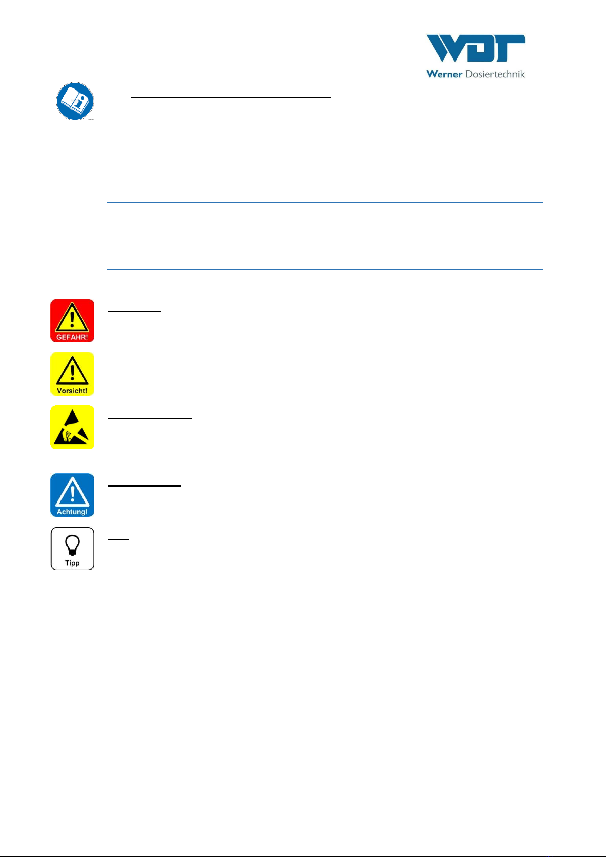
1.3 Symbols used ..............................................................................................................................................4
1.4 Warranty....................................................................................................................................................5
1.5 Further information ....................................................................................................................................5
2Safety.......................................................................................................................................................6
2.1 Intended use ...............................................................................................................................................6
2.2 Safety notices..............................................................................................................................................6
2.2.1 Handling of chemicals, risks to humans and the environment .....................................................................6
2.2.2 Protective measures and rules of conduct...................................................................................................6
3Product description - scope of delivery....................................................................................................7
3.1 Scope of delivery / accessories ...................................................................................................................7
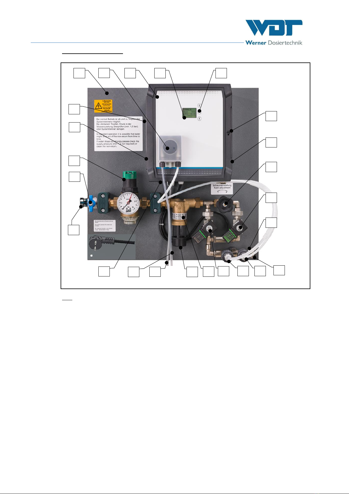
3.2 Product description.....................................................................................................................................7
3.2.1 Dosing Unit.................................................................................................................................................9
3.2.2 Control unit ................................................................................................................................................9
3.2.3 Compressor................................................................................................................................................9
3.2.4 System separator ........................................................................................................................................9
3.2.5 Button plate ................................................................................................................................................9
3.2.6 Suction lance.............................................................................................................................................10
3.2.7 Drain valve (accessory) .............................................................................................................................10
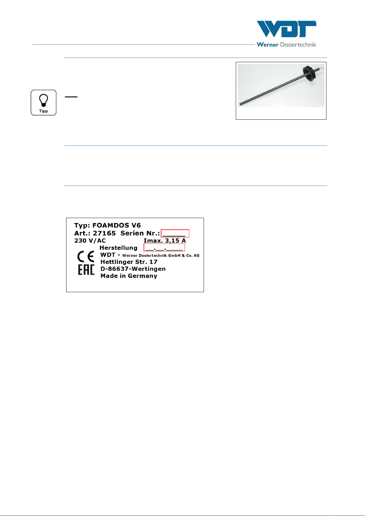
3.3 Device identification / identification plate .................................................................................................10
3.4 Technical data ...........................................................................................................................................11
3.5 Transport / storage ..................................................................................................................................12
3.5.1 Storage of foam concentrate.....................................................................................................................12
4Installation..............................................................................................................................................13
4.1 Select the installation site ..........................................................................................................................13
4.2 Installation instructions (suggested installation) .........................................................................................13
4.3 Mechanical installation...............................................................................................................................13
4.3.1 Install mounting plate with control unit .....................................................................................................13
4.3.2 Install the button plate ..............................................................................................................................13
4.4 Hydraulic installation.................................................................................................................................14
4.5 Electrical installation..................................................................................................................................16
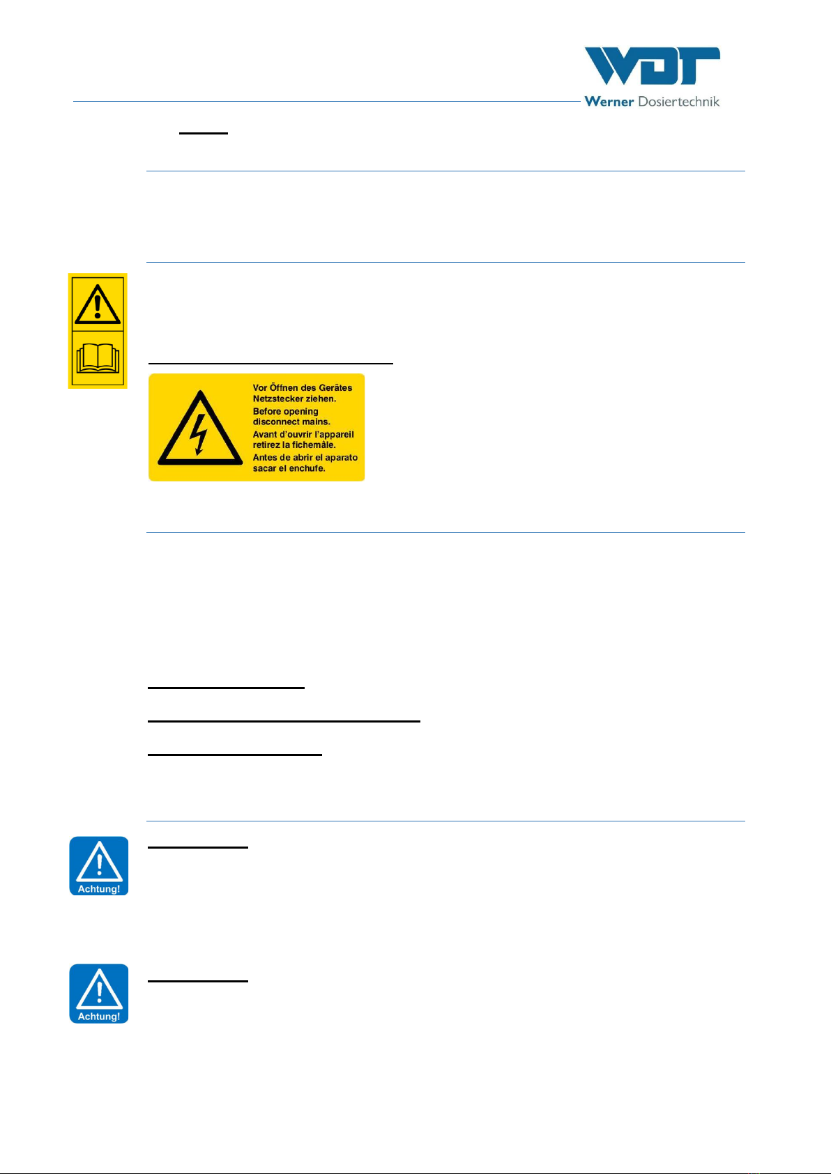
4.5.1 Open/ close the housing...........................................................................................................................16
4.5.2 Establish electrical connection ...................................................................................................................16
5Commissioning.......................................................................................................................................17
5.1 Commissioning - remarks .........................................................................................................................17
5.2 Commissioning works...............................................................................................................................17
5.2.1 Prepare the foam concentrate ..................................................................................................................17
5.2.2 Insert the roller carrier at the fragrance pump..........................................................................................17
5.2.3 Establish power supply..............................................................................................................................18
6Operation / service ...............................................................................................................................19
6.1 General.....................................................................................................................................................19
6.2 Control unit - Software .............................................................................................................................19
6.3 Switch on Foamdos V6 .............................................................................................................................20
6.4 Button plate function ................................................................................................................................20
6.5 Control unit menus ...................................................................................................................................21
6.5.1 Foam time.................................................................................................................................................21
6.5.2 Flush time .................................................................................................................................................21
6.5.3 Pressure reduction....................................................................................................................................21
6.5.4 Test foam..................................................................................................................................................22
6.5.5 Test compressor .......................................................................................................................................22
6.5.6 Test SV flush .............................................................................................................................................22
6.5.7 Test SV foam ............................................................................................................................................22
6.5.8 Test emptying (accessory drain valve).......................................................................................................22
6.5.9 Test pump.................................................................................................................................................22
6.5.10 Test fault (not conducted by the factory) ..................................................................................................23
6.5.11 Emptying foam line (accessory) .................................................................................................................23
6.5.12 Emptying time (accessory emptying foam line)..........................................................................................23
6.5.13 Emptying type (accessory emptying foam line)..........................................................................................23