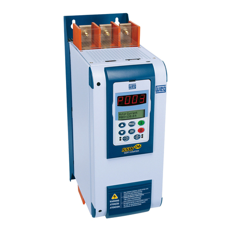
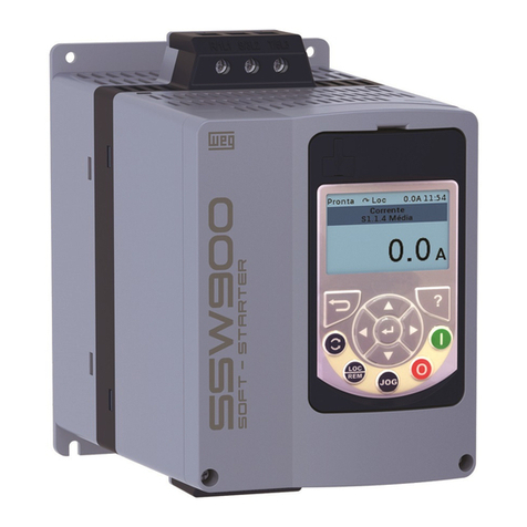
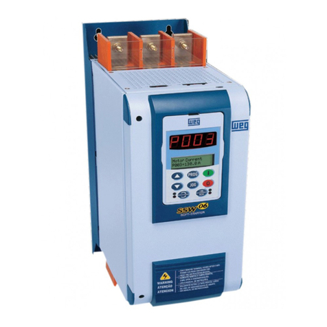
WEG SSW-06.0205 User manual


Serie: SSW-06
Software: version1.3X
0899.5579 E/6
SOFT-STARTER
MANUALSSW-06
ATTENTION!
It is very important to check if the
Soft-Starter Software is the same as
mentioned above.
12/2006

SummaryofRevisions
The table belowdescribes the revisions made to this manual.
Revision Description Section
1 FirstEdition -
2 General Revision -
3 General Revision -
4 New Software Version -
5 Implementation of the following current: 412A, Chap 3
480A, 604A, 670A, 820A, 950A, 1100A and 1400A. and 10
New software version with: braking methods 3, 4, 6
FWD/REVandJog. and 8
P140 was changed. E73 was eliminated.
E71 and E76 were changed.
6 General Revision -

Summary
Quick Parameter Reference,
Fault and Status Messages
I Parameters..................................................................................... 09
II Fault Messages.............................................................................. 17
III OtherMessages............................................................................. 17
CHAPTER 1
Safety Notices
1.1 Safety Notices in the Manual.......................................................... 18
1.2 Safety Notice on the Product.......................................................... 18
1.3 PreliminaryRecommendations....................................................... 19
CHAPTER 2
General Information
2.1 About this Manual .......................................................................... 20
2.2 SoftwareVersion............................................................................. 20
2.3 About the Soft-Starter SSW-06....................................................... 20
2.4 Soft-Starter SSW-06Identification .................................................. 23
2.5 ReceivingandStorage .................................................................... 25
CHAPTER 3
Installation and Connection
3.1 Mechanical Installation ..................................................................... 26
3.1.1EnvironmentConditions .............................................................. 26
3.1.2Dimensionsof theSoft-StarterSSW-06...................................... 26
3.1.3Mounting Specifications.............................................................. 27
3.1.3.1 Mounting inside a Panel .................................................... 28
3.1.3.2 Mounting on a surface ....................................................... 30
3.2 Electrical Installation......................................................................... 31
3.2.1 PowerTerminals ......................................................................... 32
3.2.2Locationof the Power/ Grounding,Control Connections and
Fan Voltage Selection ................................................................ 36
3.2.3RecommendedPower/GroundingCables ................................... 38
3.2.4AC Input Connection ................................................................... 39
3.2.4.1 Power Supply Capacity ..................................................... 40
3.2.4.2Recommended Fuses ....................................................... 40
3.2.5OutputConnection...................................................................... 41
3.2.5.1StandardThree-WireConnection(P150=0=Inactive).......... 41
3.2.5.2Inside DeltaMotorConnection (P150=1=Active) ............... 42
3.2.6GroundingConnections .............................................................. 43
3.2.7 Fan Connection and Selection of Fan Voltage ............................ 44
3.2.8SignalandControConnections .................................................. 45
3.2.9 RS-232,X2 SerialCommunicationConnection ........................... 48

Summary
3.2.10RS-485,XC8IsolatedSerialCommunication
Board Connection .................................................................... 48
3.2.11 XC6Fieldbus CommunicationBoardConnection ...................... 48
3.3RecommendedSet-Ups.................................................................... 48
3.3.1RecommendedSet-upsbyKeypad (HMI)Command
with Isolating Contactor. Notes in 3 .3. ....................................... 50
3.3.2RecommendedSet-upsbyKeypad (HMI)Command
with Circuit-breaker. Notes in 3.3................................................ 50
3.3.3Recommended Set-ups withCommandviaTwo-wire
Digital Inputs. Notes in 3.3. ........................................................ 51
3.3.4RecommendedSet-upswithCommandviaThree-wire
Digital Inputs. Notes in 3.3. ........................................................ 51
3.3.5RecommendedSet-upswithCommandviaThree-wire
Digital Input and Inside Delta Motor Connection. Notes in 3.3
and3.2.5.2. ................................................................................ 52
3.3.6RecommendedSet-upswithCommandviaThree-wire
Digital Inputor Serial Communication. Notes in 3.3. .................. 52
3.3.7RecommendedSet-upswithCommandviaThree-wire
DigitalInput or Fieldbus Communication.Notes in 3.3. .............. 53
3.3.8 RecommendedSetupwithCommandvia DigitalInputsand
direction of rotation ..................................................................... 53
3.3.9 RecommendedSetupwithCommandvia DigitalInputsand
ReverseBraking ......................................................................... 54
3.3.10Recommended Setup withCommand via Digital Inputs and
Optimal Braking ....................................................................... 54
3.3.11 RecommendedSetupwithCommand via DigitalInputsand
DC-Braking............................................................................... 55
3.3.12Recommended Setup withCommand viaDigital Inputsand
External By-pass Contactor ..................................................... 55
3.3.13 Symbols ................................................................................... 56
3.4 EuropeanDirectivesfor ElectromagneticCompatibility
Requirementsforinstallation .......................................................... 57
3.4.1Installation .................................................................................. 57
CHAPTER 4
Keypad (HMI) Operation
4.1 Descriptionofthe Keypad (HMI-SSW-06) ..................................... 59
4.2 Use of the Keypad (HMI) ................................................................ 61
4.2.1Keypad Use forSoft-Starter SSW-06 Operation ......................... 61
4.2.2HMI Display-Signalingindications............................................... 62
4.2.3 ParameterViewingandProgramming......................................... 63
CHAPTER 5
Start-up
5.1 Power-upPreparation ..................................................................... 65
5.2 InitialPower-up ............................................................................... 66
5.3 Start-up........................................................................................... 73
5.3.1 Start-upOperationviaKeypad(HMI)-
Summary
Typeof Control: VoltageRamp .................................................. 74
CHAPTER 6
Detailed Parameter Description
6.1 Access and Read-OnlyParameters - P000 to P099 ...................... 77
6.2 RegulationParameters - P100to P199 .......................................... 82
6.3 ConfigurationParameters- P200toP299....................................... 91
6.4 CommunicationParameters - P300toP399 .................................. 104
6.5 Motor Parameters - P400 toP499 .................................................. 106
6.6 Special Function Parameters - P500 to P599................................. 107
6.7 Protection Parameters - P600 to P699 ........................................... 113
CHAPTER 7
Applications and Programming
7.1Applications andProgramming ......................................................... 121
7.1.1 Starting byVoltage Ramp (P202=0)............................................ 123
7.1.2 Starting byCurrent Limit (P202=1).............................................. 124
7.1.3StartingbyCurrent Ramp (P202=4) ............................................ 125
7.1.4StartingbyCurrent Ramp (P202=4) ............................................ 126
7.1.5 Starting withPump Control (P202=2).......................................... 127
7.1.6StartingwithTorqueControl(P202=3)......................................... 129
7.1.6.1 Loads with constant torque (P202=3 and P120=1 point) .... 130
7.1.6.2 Loads with high initial torque (P202=3 and P120=3 points) 130
7.1.6.3 Loads with constant torque and S speed curve
(P202=3 and P120=3 points) ............................................. 131
7.1.6.4 Loads with quadratic torqueand S speed curve
(P202=3 and P120=2 points) ............................................. 131
7.1.6.5Loadswithquadratictorqueandlinear speedcurve
(P202=3 and P120=3 points) ............................................. 132
7.1.6.6 Loads with quadratic torque and higher initial torque
(P202=3 and P120=3 points) ............................................. 132
7.1.6.7 Hydraulic pump load type (P202=3).................................... 133
7.2Protections and Programming .......................................................... 136
7.2.1 ThermalClasses......................................................................... 136
7.2.1.1 Suggestions about thermal class setting............................ 136
7.2.1.2Exampleof howto program theThermal Class .................. 137
7.2.1.3Time reduction when changing from cold starting
to hot starting ..................................................................... 138
7.2.1.4 Service Factor .................................................................... 138
CHAPTER 8
Diagnosis and Troubleshooting
8.1 Faults and Possible Causes ............................................................. 139
8.2Troubleshooting ................................................................................ 143

Summary
8.3Contacting WEGTelephone/Fax/E-mail forContact (Servicing) ........ 143
8.4PreventiveMaintenance .................................................................... 144
8.4.1Cleaning Instructions .................................................................. 145
8.5 Spare Parts List................................................................................ 145
CHAPTER 9
Options and Accessories
9.1Remote Keypad (HMI) and Cables.................................................... 146
9.2RS-485for theSoft-StarterSSW-06 ................................................. 148
9.2.1 RS-485 Communication Kitfor the SSW-06 ............................... 148
9.2.2OptionalMIW-02Module ............................................................ 149
9.3 Fieldbus Communication Kits ........................................................... 149
9.3.1Fieldbus DeviceNet Communication Kit for the SSW-06............. 149
9.3.2 Fieldbus Profibus DP Communication kit for the SSW-06 .......... 150
CHAPTER 10
Technical Specifications
10.1 Currentsand RatingsAccordingtoUl508 ....................................... 151
10.2 Currents and Ratings for IP55, IV PoleWeg Motor......................... 152
10.3 PowerData..................................................................................... 153
10.4 Electronics/ProgrammingData....................................................... 153
10.5 MechanicalData............................................................................. 155

9
SSW-06 - QUICK PARAMETER REFERENCE
QUICK PARAMETER REFERENCE, FAULT AND STATUS MESSAGES
Software:V1.3X
Application:
Model:
SerialNumber:
PersonResponsible:
Date: / / .
I.Parameters
Parameter Description Adjustable Range Factory Unit User´s Page
Setting Setting
P000 Access Parameter 0 to 999 0 - 77
READ ONLY PARAMETERS P001 to P099
P001 Soft-Starter Current 0 to 999.9 - % 78
(%In of the Soft-Starter)
P002 Motor Current (%In of the Motor) 0 to 999.9 -% 78
P003 Motor Current 0 to 9999.9 -A 78
P004 Power Supply Voltage 0 to 999 -V 78
P005 Network Frequency 0 to 99.9 - Hz 78
P006 Soft-Starter Status 0=rdy - ready - - 78
1=Sub - Sub
2=Exx - Error
3=ruP - Run Up
4=FuLL - Full Volt.
5=PASS - By-pass
6=ECO - Reserved
7=rdo - Run Down
8=br - Braking
9=rE- FWD/REV
10=JOG- JOG
11=dly - Delay P630
12=G.di - Gen. Disable
P007 Output Voltage 0 to 999 - V 79
P008 Power Factor 0 to 1.00 - - 79
P009 Motor Torque (% Tn of the Motor) 0 to 999.9 - % 79
P010 Output Power 0 to 6553.5 - kW 79
P011 Apparent Output Power 0 to 6553.5 - kVA 79
P012 Digital Input Status Dl1 to Dl6 0 = Inactive - - 80
1 = Active
P013 Status RL1, RL2 and RL3 0 = Inactive - - 80
1 = Active
P014 Last Fault 03 to 77 - - 81
P015 Second Previous Fault 03 to 77 - - 81
P016 Third Previous Fault 03 to 77 - - 81
P017 Fourth Previous Fault 03 to 77 - - 81
P023 Software Version X.XX - - 81
P030 Current of Phase R 0 to 9999.9 -A 81
P031 Current of Phase S 0 to 9999.9 -A 81
P032 Current of Phase T 0 to 9999.9 -A 81
P033 R-S Line Voltage 0 to 999 -V 81
P034 S-T Line Voltage 0 to 999 -V 81
P035 T-R Line Voltage 0 to 999 -V 81

SSW-06 - QUICK PARAMETER REFERENCE
10
Parameter Description Adjustable Range Factory Unit User´s Page
Setting Setting
P042 Time Powered 0 to 65530 -h 81
P043 TimeEnabled 0 to 6553 - h 82
P050 Motor Thermal Protection Status 0 to 250 - % 82
P085 Fieldbus Communication Board Status 0=Off - - 82
1=Board Inactive
2=Board Active and Offline
3=Board Active and Online
REGULATION PARAMETERS P100 TO P199
Voltage Ramp
P101 Initial Voltage (% Un of the motor) 25 to 90 30 % 82
P102 AccelerationRamp Time 1 to 999 20 s 83
P103 Deceleration Voltage Step 100=Inactive 100=Inactive % 84
(% Un of the motor) 99 to 60
P104 DecelerationRampTime 0=Inactive 0=Inactive s 84
1 to 299
P105 End Deceleration Voltage 30 to 55 30 % 84
(% Un of the Motor)
Current Limit
P110 Current Limit 150 to 500 300 % 84
(%In of the Motor current)
P111 Initial Current for the Current Ramp 150 to 500 150 % 85
(% In of the Motor)
P112 Time for the Current Ramp 1 to 99 20 % 85
(% of P102)
Torque Control
P120 (1) Starting Torque Characteristics 1=Constant 1=Constant - 86
2=Linear
3=Quadratic
P121 Initial Starting Torque (% Tn of Motor) 10 to 400 30 % 87
P122 End Starting Torque (% Tn of Motor) 10 to 400 110 % 87
P123 Minimum StartingTorque 10 to 400 27 % 87
(% Tn of the Motor)
P124 Time for the Minimum Start Torque 1 to 99 20 % 87
(% of P102)
P125 (1) Stopping Torque Characteristics 1=Constant 1=Constant - 88
2=Linear
3=Quadratic
P126 End Stop Torque (% Tn of the Motor) 10 to 100 20 % 88
P127 MinimumStopTorque 10 to 100 50 % 89
(% Tn of the Motor)
P128 Time forthe Minimum Stop Torque 1 to 99 50 % 89
(% of P104)
Pump Control
P130 (1) PumpControl 0=PumpI 0=PumpI - 89
1=PumpII
By-pass
P140 (1) External By-pass Contactor 0=Inactive 0=Inactive - 89
1=Active

11
SSW-06 - QUICK PARAMETER REFERENCE
Parameter Description Adjustable Range Factory Unit User´s Page
Setting Setting
Inside Delta
P150 (1) (2) Inside Delta Motor Connection 0=Inactive 0=Inactive - 90
1=Active
CONFIGURATION PARAMETERS P200 to P399
P200 Password 0=Inactive 1=Active - 91
1=Active
P201 (2) Language Selection 0=Portuguese To be defined - 91
1=English by the user
2=Spanish
3=German
P202 (1) Type of the Control 0=VoltageRamp 0=VoltageRamp - 91
1=Currentlimiting
2=PumpControl
3=Torque Control
4=Current Ramp
P204 (1) Load/Save Parameters 0=Not use 0=Not use - 94
1=Not use
2=Not use
3=Reset P043
4=Not use
5=Loads Factory Default
6=Not use
7=Loads User Default 1
8=Loads User Default 2
9=Not use
10=Saves User Default 1
11=Saves User Default 2
P205 Display Default Selection 0=P001 2=P003 - 95
1=P002
2=P003
3=P004
4=P005
5=P006
6=P007
7=P008
P206 Auto-Reset Time 0=Inactive 0=Inactive s 95
1 to 600
P215(1) Keypad Copy Function 0=Inactive 0=Inactive - 96
1=SSW HMI
2=HMISSW
P218 LCD Display Contrast Adjust. 0 to 150 127 - 97
Local/Remote Definition
P220 (1) Local/Remote Source Selection 0=Always Local 2=HMI(L) - 97
1=Always Remote
2=HMI(L)
3=HMI(R)
4=DI4toDI6
5=Serial(L)
6=Serial(R)
7=Fieldbus(L)
8=Fieldbus(R)

SSW-06 - QUICK PARAMETER REFERENCE
12
Parameter Description Adjustable Range Factory Unit User´s Page
Setting Setting
P229 (1) Local StatusCommand Selection 0=KeysHMI 0=Keys HMI - 97
1= Digital Inputs DIx
2=Serial
3=Fieldbus
P230 (1) RemoteStatusCommandSelection 0=KeysHMI 1=DIxTerminals - 97
1= Digital Inputs DIx
2=Serial
3=Fieldbus
P231 (1) FWD/REVSelection 0=Not used 0=Not used - 98
1=By Contactor
2=JOGOnly
Analog Outputs
P251 AO1 (0 to 10)V Output Function 0=Not used 0=Not used - 99
1= Current (%In of the SSW)
2=Input Voltage
(%Un of the SSW)
3=Output voltage
(%Un of the SSW)
4=Power Factor
5=Thermal Protection
6=Power (in W)
7=Power (in VA)
8=Torque (%Tn of Motor)
9=Fieldbus
10=Serial
P252 AO1 Analog Output Gain 0.000 to 9.999 1.000 - 99
P253 AO2 (0 to 20)mA or (4 to 20)mA 0=Not used 0= Not used - 99
Output Function 1= Current (%In of the SSW)
2=Input Voltage
(%Un of the SSW)
3=Output voltage
(%Un of the SSW)
4=Power Factor
5=Thermal Protection
6=Power (in W)
7=Power (in VA)
8=Torque (%Tn of the Motor)
9=Fieldbus
10=Serial
P254 AO2 Analog Output Gain 0.000 to 9.999 1.000 - 99
P255 AO2 Analog Output Selection 0=0 to 20 0=0 to 20 mA 99
1=4 to 20
Digital Inputs
P264 (1) DI2Digital Input Function 0=Not Used 2= Reset - 100
1=Stop (Three-Wire)
2=Reset
P265 (1) DI3Digital Input Function 0=Not Used 0=Not used - 100
1=GeneralEnable
2=Reset

13
SSW-06 - QUICK PARAMETER REFERENCE
Parameter Description Adjustable Range Factory Unit User´s Page
Setting Setting
P266 (1) DI4Digital Input Function 0=Not Used 0=Not Used - 100
1=FWD/REV
2=Local/Remote
3=NoExternalFault
4=JOG
5=Brake Off
6=Reset
P267 (1) DI5Digital Input Function 0=Not Used 0=Not used - 101
1=FWD/REV
2=Local/Remote
3=NoExternalFault
4=JOG
5=Brake Off
6=Reset
P268 (1) DI6Digital Input Function 0=Not used 0=Not used - 101
1=FWD/REV
2=Local/Remote
3=No external Fault
4=JOG
5=Brake Off
6=Reset
7=MotorThermistor
Digital Outputs
P277 (1) RL1 Relay Function 0=Not used 1=Running - 102
1=Running
2=Fullvoltage
3=External By-pass
4=FWD/REV-K1
5=DC-Brake
6=No Fault
7=Fault
8=Fieldbus
9=Serial
P278 (1) RL2 Relay Function 0=Not used 2=FullVoltage - 102
1=Running
2=Fullvoltage
3=External By-pass
4=FWD/REV-K2
5=DC-Brake
6=No Fault
7=Fault
8=Fieldbus
9=Serial
P279 (1) RL3 Relay Function 0=Inactive 6=No Fault - 102
1=Running
2=Fullvoltage
3=External By-pass
4= Not used
5=DC-Brake
6=No Fault

SSW-06 - QUICK PARAMETER REFERENCE
14
Parameter Description Adjustable Range Factory Unit User´s Page
Setting Setting
7=Fault
8=Fieldbus
9=Serial
Soft-Starter Data
P295 (1)(2) SSW Rated Current 0=10A 11=312A According to A 103
1=16A 12=365A Soft-Starter
2=23A 13=412A Rated Current
3=30A 14=480A
4=45A 15=604A
5=60A 16=670A
6=85A 17=820A
7=130A 18=954A
8=170A 19=1100A
9=205A 20=1411A
10=255A
P296 (1) (2) Rated Voltage 0=220/575V According to V 103
1=575/690V Soft-Starter
Voltage
PARÂMETROS DE COMUNICAÇÃO SERIAL P300 a P399
P308 (1)(2) Soft-Starter Address on the Serial 1 to 247 1 - 104
Communication Network
P309 (1)(2) FieldbusCommunication 0=Inactive 0=Inactive - 104
BoardEnabling 1=Profibus-DP
(1 Inputs and 1 Outputs)
2=Profibus-DP
(4 Inputs and 4 Outputs)
3=Profibus-DP
(7 Inputs and 7 Outputs)
4=DeviceNet
(1 Inputs and 1 Outputs)
5=DeviceNet
(4 Inputs and 4 Outputs)
6=DeviceNet
(7 Inputs and 7 Outputs)
P312 (1)(2) Protocol Type and Serial 1=Modbus-RTU 1=Modbus-RTU 104
Communication Transfer Rate (9600bps, no parity) (9600bps,
2=Modbus-RTU no parity)
(9600bps, odd)
3=Modbus-RTU
(9600bps, even)
4=Modbus-RTU
(19200bps, no parity)
5=Modbus-RTU
(19200bps, odd)
6=Modbus-RTU
(19200bps, even)
7=Modbus-RTU
(38400bps, no parity)
8=Modbus-RTU
(38400bps, odd)

15
SSW-06 - QUICK PARAMETER REFERENCE
Parameter Description Adjustable Range Factory Unit User´s Page
Setting Setting
9=Modbus-RTU
(38400bps, even)
P313 Serialand Fieldbus Communication 0=Inactive 0=Inactive 104
ErrorActions (E28, E29 and E30) 1=Disable
2=GeneralEnable
3=Changes to Local
P314(1) Timeout Time forSerial 0 to 999 0= Inactive s 105
CommunicationTelegram Reception
P315 (1) Read Parameter via Fieldbus 1 0 to 999 0 - 105
P316 (1) Read Parameter via Fieldbus 2 0 to 999 0 - 105
P317 (1) Read Parameter via Fieldbus 3 0 to 999 0 - 105
MOTOR PARAMETERS P400 to P499
P400 (1) Rated Motor Voltage 0 to 999 380 V 106
P401 (1) Rated Motor Current 0.0 to 1500 20 A 106
P403 (1) Rated Motor Speed 400 to 3600 1780 rpm 106
P404 (1) Rated Motor Power 0.1 to 2650 75 kW 106
P405 (1) Motor Power Factor 0 to 1.00 0.89 - 106
P406 (1) Service Factor 0 to 1.50 1.00 - 106
SPECIAL PARAMETERS P500 to P599
Braking
P500 (1) Braking Methods 0=Inactive 0=Inactive - 107
1=Reverse Braking
2=OptimalBraking
3=DC-Braking
P501 BrakingTime 1 to 299 10 s 110
P502 Braking Voltage Level 30 to 70 30 % 110
P503 Braking End Detection 0=Inactive 0=Inactive - 110
1=Automatic
JOG
P510 (1) Jog 0=Inactive 0=Inactive - 111
1=Active
P511 Jog Level 10 to 100 30 % 111
Kick Start
P520 (1) Kick Start Torque Pulse 0=Inactive 0=Inactive - 112
(according to P202) 1=Active
P521 Kick Start PulseTime 0.1 to 2 0.1 s 112
P522 Kick Start Voltage Pulse Level 70 to 90 70 % 112
(% Un of the Motor)
P523 Kick Start Current Pulse Level 300 to 700 500 % 112
(% In of the Motor)
PROTECTION PARAMETERS P600 to P699
Voltage Protection
P600 (1) Undervoltage (% Un of the motor) 0 to 30 20 % 113
P601 (1) ImmediateUndervoltageTime 0=Inactive 1 s 113
1 to 99
P602 (1) Overvoltage (% Un of the motor) 0 to 20 15 % 113
P603 (1) Immediate OvervoltageTime 0=Inactive 1 s 113
1 to 99
P604 (1) Voltage Imbalance Between Phases 0 to 30 15 % 114
(% Un of the motor)

SSW-06 - QUICK PARAMETER REFERENCE
16
Parameter Description Adjustable Range Factory Unit User´s Page
Setting Setting
Notes presented on quick parameter description:
(1) This parameter can only be changed with the motor stopped.
(2) This parameter does not change when factory defaults are loaded (P204=5).
P605 (1) Phase Voltage Imbalance Time 0=Inactive 1 s 114
1 to 99
Current Protection
P610 (1) Immediate Undercurrent 0 to 99 20 % 114
(% In of the motor)
P611 (1) ImmediateUndercurrent Time 0=Inactive 0=Inactive s 114
1 to 99
P612 (1) ImmediateOvercurrent 0 to 99 20 % 114
(% In of the motor)
P613 (1) Immediate Overcurrent Time 0=Inactive 0=Inactive s 114
1 to 99
P614 (1) Current Imbalance between Phases 0 to 30 15 % 115
(% In of the motor)
P615 (1) Current Imbalance Between 0=Inactive 1 s 115
Phase Times 1 to 99
P616 (1) Undercurrent before Closing 0=Inactive 1=Active - 115
of Internal By-pass 1=Active
P617 Motor Overcurrent before By-pass 0=Inactive 1=Active - 115
1=Active
Phase Sequence
P620 (1) RST Phase Current Sequence 0=Inactive 0=Inactive - 115
1=Active
Interval between Starts
P630 Interval of Time after Stop 2 to 999 2 s 115
Motor Thermal Protection
P640 (1) Motor Protection Thermal Class 0=Inactive 5=25 6=30 - 117
of Motor Protection 1=5 6=30
2=10 7=35
3=15 8=40
4=20 9=45
P641 (1) Auto-Reset of thermal Memory 0=Inactive 0=Inactive s 120
1 to 600

17
SSW-06 - QUICK PARAMETER REFERENCE
II.FaultMessages
III.OtherMessages
Display Description Page
E03 Undervoltage, Phase Fault or Phase 139
Unbalancing
E04 Overtemperature at the Power Assembly 139
E05 Motor Overload 139
E06 External Fault (DI) 139
E10 Copy Function Fault 139
E15 Motor is not Connected or SCRs in Short-circuit 139
E16 Overvoltage 139
E24 ProgrammingError 140
E28 Timeout in theTelegram Reception 140
E29 Fieldbus Communication is Inactive 140
E30 Fieldbus Board is Inactive 140
E31 HMIConnectionFault 140
E32 Motor Overtemperature (DI) 140
E41 Self-Diagnosis Fault 140
E62 StartLimitingTime 140
E63 Locked Rotor 140
E65 Undercurrent 141
E66 Overcurrent 141
E67 Inverted Phase Sequence 141
E70 Undervoltage at the Electronics 141
E71 Bypass Contact is Open 141
E72 Overcurrent before By-pass Contact 141
E74 Current Imbalance 141
E75 Frequency of Supply Line 141
out of Permitted Range
E76 Undercurrent before By-pass 141
E77 Bypass Contact is closed or SCRs in Short-circuit 141
For more details see table 8.1 in chapter 8.
Display Description
rdy Soft-Starter is ready to be enabled
ruP Soft-Starter is enabled according to “ramp up”
FuLL Soft-Starter is enabled at “full voltage”
PASS Soft-Starter is enabled with “By-pass”
rdo Soft-Starter is enabled according to “ramp down”
br Soft-Starter is enabled according to “braking”
rE Soft-Starter is enabled according to “reversing”
JOG Soft-Starter is enabled according to “jog”
Sub Soft-Starter under voltage fault
Exx Soft-Starter fault
dly Soft-Starter esperando o tempo após parada "delay"
G.di Soft-Starter com desabilita geral "general disable"
ECO Reserved

18
SAFETY NOTICES
ThisManualcontainsallnecessaryinformationforthecorrectinstallation
andoperation of the SSW-06 Soft-Starter.
TheSSW-06InstructionManualhasbeenwrittenforqualifiedpersonnel
with suitable training or technical qualifications to operate this type of
equipment.
The following SafetyNotices will be used in this Manual:
DANGER!
IftherecommendedSafetyInstructionsarenotstrictlyobserved,serious
or fatal injuries of personnel and/or equipment damage can occur.
ATTENTION!
Failure to observe the recommended Safety Procedures can lead to
materialdamage.
NOTE!
ThecontentofthisManualsuppliesimportantinformationforthecorrect
understandingofoperationandproper performanceof theequipment.
1.1 SAFETYNOTICES
INTHEMANUAL
1.2 SAFETYNOTICESON
THEPRODUCT Thefollowingsymbolsmaybeattachedtotheproduct,servingasSafety
Notices:
High Voltages
Componentsaresensitivetoelectrostatic discharge.Donottouch
them without following proper grounding procedures.
Mandatoryconnection to ground protection (PE)
Shield connection to ground
CHAPTER 1

CHAPTER 1 - SAFETY NOTICES
19
NOTE!
In this Manual, qualified personnel are defined as peoplethat are trained to:
1. Install, ground, power-up and operate theSSW-06 accordingto this
Manualand the local required safetyprocedures;
2. Use of safety equipment according to the local regulations;
3. Administer FirstAid Treatment.
DANGER!
Always disconnect the main power supply before touching any electrical
component associated tothe SSW-06 Soft-Starter.
High voltages and spinning parts (fans) may be present even after switching
offthepower supply. Waitatleast3minutesforthecompletedischargeofthe
capacitors.
Always connect the equipment frame to the protection earth (PE) in the
appropriate place forthis.
ATTENTION!
All electronic boards have components that are sensitive to electrostatic
discharges.Nevertouchanyoftheelectricalcomponentsorconnectorswithout
followingpropergroundingprocedures.Ifnecessarytodoso,touchtheproperly
grounded metallic frame or use a suitableground strap.
NOTE!
Soft-StarterSSW-06caninterferewithother electronic equipment.Inorderto
reduce this interference, adopt the measures recommended in Section 3
“Installation”.
NOTE!
Readthisentiremanualcarefullyandcompletelybeforeinstallingoroperating
theSoft-Starter SSW-06.
Do not apply high voltage (High Pot) test on Soft-Starter SSW-06!
If this test is necessary, contact the manufacturer
DANGER!
Only qualified personnel should plan or implement the installation, start-up,
operationandmaintenanceofthisequipment.Personnelmustreviewthisentire
Manual before attempting to install, operate or troubleshootthe SSW-06.
These personnel must follow all safety instructions included in this Manual
and/ordefinedbylocalregulations.
Failure to complywith these instructions mayresult inpersonnel injuryand/or
equipmentdamage.
1.3 PRELIMINARY
RECOMMENDATIONS

20
GENERAL INFORMATION
This chapter defines the contents and purpose of this manual and
describes the main characteristics of the SSW-06 Soft-Starter.
Identification of the SSW-06, receiving and storage requirements are
alsoprovided.
This Manual is divided into 10 Chapters, providing information to the
user on how to receive, install, start-up and operate the Soft-Starter
SSW-06.
Chapter 1- Safety Notices;
Chapter 2- GeneralInformation;ReceivingandStoringoftheSSW-06;
Chapter 3 - Information about InstallationandConnection ofthe
Soft-Starter SSW-06 power and controlcircuit), how to
installoptionsandrecommendeddrives;
Chapter 4 - Using the Keypad (HumanMachineInterface - HMI);
Chapter 5- Informationaboutrunningandstepsto befollowed;
Chapter 6 - Detailed description of all Soft-Starter SSW-06
programmingparameters;
Chapter7- Informationand suggestions on how to program the
types of control and protections
Chapter 8- InformationaboutDiagnosticsandTroubleshooting,
cleaninginstructionsand preventivemaintenance;
Chapter 9- SW-06Soft-Starteroptionaldevices;
Chapter 10- Tablesand technicalinformation aboutthe power lines
of the Soft-Starter SSW-06;
ThisManualprovidesinformation forthecorrectuseof theSoft-Starter
SSW-06.DuetothevariousfunctionsoftheSoft-Starter SSW-06many
different modes of operation arepossible.
As the Soft-Starter SSW-06 can be applied in several ways, it is
impossible to describe here all application possibilities, neither can
WEG assume any responsibility when the Soft-Starter SSW-06 is not
used according to this Manual.
No part of this Manual maybe reproduced in anyform, without written
permissionfrom WEG.
It is important to note the Software Version installed in the Soft-Starter
SSW-06,sinceitdefinesthefunctionsandtheprogrammingparameters
oftheSoft-Starter.ThisManualreferstotheSoftwareversionindicated
on the inside cover. For example, the Version 1.0X appliesto versions
1.00to1.09,where“X”isavariablethatwillchangeduetominorsoftware
revisions.
The Software Version can be read the Parameter P023.
The Soft-Starter SSW-06is ahigh performance Drivethat permitsthe
start Control of three-phase AC induction motors. The Soft-Starter
SSW-06 prevents mechanical shocks on the load and current peaks
in the supply line.
Amongthemaincharacteristicsofthisproductisitslineandconnection
fault detection capacity thus enabling the customer to chose the best
way of protecting his the motor, such as:
2.1 ABOUTTHISMANUAL
2.2 SOFTWARE VERSION
2.3 ABOUTTHE
SOFT-STARTER
SSW-06
CHAPTER 2
This manual suits for next models
14
Table of contents
Other WEG Controllers manuals

WEG
WEG SSW7000 User manual

WEG
WEG PLC300 User manual

WEG
WEG SSW900 Series User manual

WEG
WEG AVR-A-OPT-04E Installation and operating instructions

WEG
WEG SSW7000 User manual

WEG
WEG GRT7-TR1 User manual

WEG
WEG PDWCA User manual

WEG
WEG SSW900 Series User manual

WEG
WEG SSW-05 Plus Series User manual

WEG
WEG SSW06 Use and care manual
Popular Controllers manuals by other brands

National Instruments
National Instruments GPIB-110 user manual

Meinberg
Meinberg TCR511PCI manual

Harpo
Harpo BraillePen 12 quick start

Norac
Norac UC5 Topcon X30 installation manual

dixell
dixell XW35VS Installing and operating instructions

Bettis
Bettis TorqPlus EM Series Installation and operating instructions