WeiderPro 5000 User manual

Part No. 227654 R0805A Printed in China © 2005 ICON IP, Inc.
CAUTION
Read all precautions and instruc-
tions in this manual before using
this equipment. Save this manual
for future reference.
Model No. WEEVSY2985.0
Serial No.
Write the serial number in the
space above for future reference.
Serial Number Decal (Under Seat)
QUESTIONS?
As a manufacturer, we are com-
mitted to providing complete
customer satisfaction. If you
have questions, or if there are
missing parts, please call:
Or write:
ICON Health & Fitness, Ltd.
Unit 4
Revie Road Industrial Estate
Revie Road
Beeston
Leeds, LS118JG
UK
email: [email protected]
USER’S MANUAL
08457 089 009
ORDERING REPLACEMENT PARTS
To order replacement parts, contact the ICON Health & Fitness, Ltd. office, or write:
ICON Health & Fitness, Ltd.
Unit 4
Revie Road Industrial Estate
Revie Road
Beeston
Leeds, LS118JG
UK
Tel:
Outside the UK: (44) 113 387 7133
Fax: (44) 113 387 7125
Please provide the following information when ordering replacement parts:
• the MODEL NUMBER of the product (WEEVSY2985.0)
• the NAME of the product (WEIDER PRO 5000 weight system)
• the SERIAL NUMBER of the product (see the front cover of this manual)
• the KEY NUMBER and DESCRIPTION of the part(s) (see the PART LIST and EXPLODED DRAWING in the
centre of this manual)
08457 089 009

19
Rest for a short period of time after each set. The
ideal resting periods are:
• Rest for three minutes after each set for a muscle
building workout.
• Rest for one minute after each set for a toning work-
out.
• Rest for 30 seconds after each set for a weight loss
workout.
Plan to spend the first couple of weeks familiarising
yourself with the equipment and learning the proper
form for each exercise.
COOLING DOWN
End each workout with 5 to 10 minutes of stretching.
Include stretches for both your arms and legs. Move
slowly as you stretch and do not bounce. Ease into
each stretch gradually and go only as far as you can
without strain. Stretching at the end of each workout
is an effective way to increase flexibility.
STAYING MOTIVATED
For motivation, keep a record of each workout. List the
date, the exercises performed, the resistance used,
and the numbers of sets and repetitions completed.
Record your weight and key body measurements at
the end of every month. Remember, the key to achiev-
ing the greatest results is to make exercise a regular
and enjoyable part of your everyday life.
O
P
Q
R
S
T
U
V
X
W
N
M
J
G
F
H
I
K
E
C
D
B
A
L
MUSCLE CHART
A. Sternomastoid (neck)
B. Pectoralis Major (chest)
C. Biceps (front of arm)
D. Obliques (waist)
E. Brachioradials (forearm)
F. Hip Flexors (upper thigh)
G. Abductor (outer thigh)
H. Quadriceps (front of thigh)
I. Sartorius (front of thigh)
J. Tibialis Anterior (front of calf)
K. Soleus (front of calf)
L. Anterior Deltoid (shoulder)
M. Rectus Abdominus (stomach)
N. Adductor (inner thigh)
O. Trapezius (upper back)
P. Rhomboideus (upper back)
Q. Posterior Deltoid (shoulder)
R. Triceps (back of arm)
S. Latissimus Dorsi (mid back)
T. Spinae Erectors (lower back)
U. Gluteus Medius (hip)
V. Gluteus Maximus (buttocks)
W. Hamstring (back of leg)
X. Gastrocnemius (back of calf)
2
WARNING DECAL PLACEMENT
WARNING DECAL PLACEMENT . . . . . . . . . . . . . . . . . . . . . . . . . . . . . . . . . . . . . . . . . . . . . . . . . . . . . . . . . . . . . 2
IMPORTANT PRECAUTIONS . . . . . . . . . . . . . . . . . . . . . . . . . . . . . . . . . . . . . . . . . . . . . . . . . . . . . . . . . . . . . . . . 3
BEFORE YOU BEGIN . . . . . . . . . . . . . . . . . . . . . . . . . . . . . . . . . . . . . . . . . . . . . . . . . . . . . . . . . . . . . . . . . . . . . . 4
ASSEMBLY . . . . . . . . . . . . . . . . . . . . . . . . . . . . . . . . . . . . . . . . . . . . . . . . . . . . . . . . . . . . . . . . . . . . . . . . . . . . . . 5
ADJUSTMENTS . . . . . . . . . . . . . . . . . . . . . . . . . . . . . . . . . . . . . . . . . . . . . . . . . . . . . . . . . . . . . . . . . . . . . . . . . . 14
CABLE DIAGRAM . . . . . . . . . . . . . . . . . . . . . . . . . . . . . . . . . . . . . . . . . . . . . . . . . . . . . . . . . . . . . . . . . . . . . . . . .16
WEIGHT RESISTANCE CHART . . . . . . . . . . . . . . . . . . . . . . . . . . . . . . . . . . . . . . . . . . . . . . . . . . . . . . . . . . . . . .17
EXERCISE GUIDELINES . . . . . . . . . . . . . . . . . . . . . . . . . . . . . . . . . . . . . . . . . . . . . . . . . . . . . . . . . . . . . . . . . . 18
ORDERING REPLACEMENT PARTS . . . . . . . . . . . . . . . . . . . . . . . . . . . . . . . . . . . . . . . . . . . . . . . . . .Back Cover
Note: A PART IDENTIFICATION CHART and a PART LIST/EXPLODED DRAWING is attached in the centre of
this manual. Remove the PART IDENTIFICATION CHART and PART LIST/EXPLODED DRAWING before begin-
ning assembly.
WEIDER is a registered trademark of ICON IP, Inc.
TABLE OF CONTENTS
The decal shown here has been placed on the
weight system in the indicated location. If the
decal is missing or illegible, please call the tele-
phone number on the front cover of this manual
and order a free replacement decal.

18
EXERCISE GUIDELINES
THE FOUR BASIC TYPES OF WORKOUTS
Muscle Building
To increase the size and strength of your muscles,
push them to a high percentage of their maximum
capacity. Your muscles will adapt and grow as you pro-
gressively increase the intensity of your exercise. You
can adjust the intensity level of an individual exercise
in two ways:
• by changing the amount of weight used
• by changing the number of repetitions or sets per-
formed. (A “repetition” is one complete cycle of an
exercise, such as one sit-up. A “set” is a series of
repetitions.)
The proper amount of weight for each exercise
depends upon the individual user. You must gauge
your limits and select the amount of weight that is right
for you. Begin with 3 sets of 8 repetitions for each
exercise you perform. Rest for 3 minutes after each
set. When you can complete 3 sets of 12 repetitions
without difficulty, increase the amount of weight.
Toning
You can tone your muscles by pushing them to a mod-
erate percentage of their capacity. Select a moderate
amount of weight and increase the number of repeti-
tions in each set. Complete as many sets of 15 to 20
repetitions as possible without discomfort. Rest for 1
minute after each set. Work your muscles by complet-
ing more sets rather than by using high amounts of
weight.
Weight Loss
To lose weight, use a low amount of weight and
increase the number of repetitions in each set.
Exercise for 20 to 30 minutes, resting for a maximum
of 30 seconds between sets.
Cross Training
Cross training is an efficient way to get a complete and
well-balanced fitness program. An example of a bal-
anced program is:
• Plan strength training workouts on Monday,
Wednesday, and Friday.
• Plan 20 to 30 minutes of aerobic exercise, such as
running on a treadmill or riding an elliptical or an
exercise cycle, on Tuesday and Thursday.
• Rest from both strength training and aerobic exercise
for at least one full day each week to give your body
time to regenerate.
The combination of strength training and aerobic exer-
cise will reshape and strengthen your body, plus devel-
op your heart and lungs.
PERSONALISING YOUR EXERCISE PROGRAM
Determining the exact length of time for each workout,
as well as the number of repetitions or sets completed,
is an individual matter. It is important to avoid overdo-
ing it during the first few months of your exercise pro-
gram. You should progress at your own pace and be
sensitive to your body’s signals. If you experience pain
or dizziness at any time while exercising, stop immedi-
ately and begin cooling down. Find out what is wrong
before continuing. Remember that adequate rest and a
proper diet are important factors in any exercise pro-
gram.
WARMING UP
Begin each workout with 5 to 10 minutes of stretching
and light exercise to warm up. Warming up prepares
your body for more strenuous exercise by increasing
circulation, raising your body temperature and deliver-
ing more oxygen to your muscles.
WORKING OUT
Each workout should include 6 to 10 different exercis-
es. Select exercises for every major muscle group,
emphasising areas that you want to develop most. To
give balance and variety to your workouts, vary the
exercises from session to session.
Schedule your workouts for the time of day when your
energy level is the highest. Each workout should be
followed by at least one day of rest. Once you find the
schedule that is right for you, stick with it.
EXERCISE FORM
Maintaining proper form is an essential part of an
effective exercise program. This requires moving
through the full range of motion for each exercise, and
moving only the appropriate parts of the body.
Exercising in an uncontrolled manner will leave you
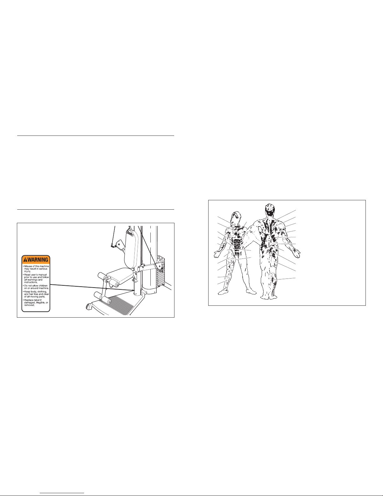
feeling exhausted. On the exercise guide accompany-
ing this manual you will find photographs showing the
correct form for several exercises, and a list of the
muscles affected. Refer to the muscle chart on the
next page to find the names of the muscles.
The repetitions in each set should be performed
smoothly and without pausing. The exertion stage of
each repetition should last about half as long as the
return stage. Proper breathing is important. Exhale
during the exertion stage of each repetition and inhale
during the return stroke. Never hold your breath.
1. Read all instructions in this manual and all
warnings on the weight system before using
the weight system. Use the weight system
only as described in this manual.
2. It is the responsibility of the owner to ensure
that all users of the weight system are ade-
quately informed of all precautions.
3. The weight system is intended for home use
only. Do not use the weight system in any
commercial, rental, or institutional setting.
4. Keep the weight system indoors, away from
moisture and dust. Place the weight system
on a level surface, with a mat beneath it to
protect the floor or carpet. Make sure that
there is enough clearance around the weight
system to mount, dismount, and use the
weight system.
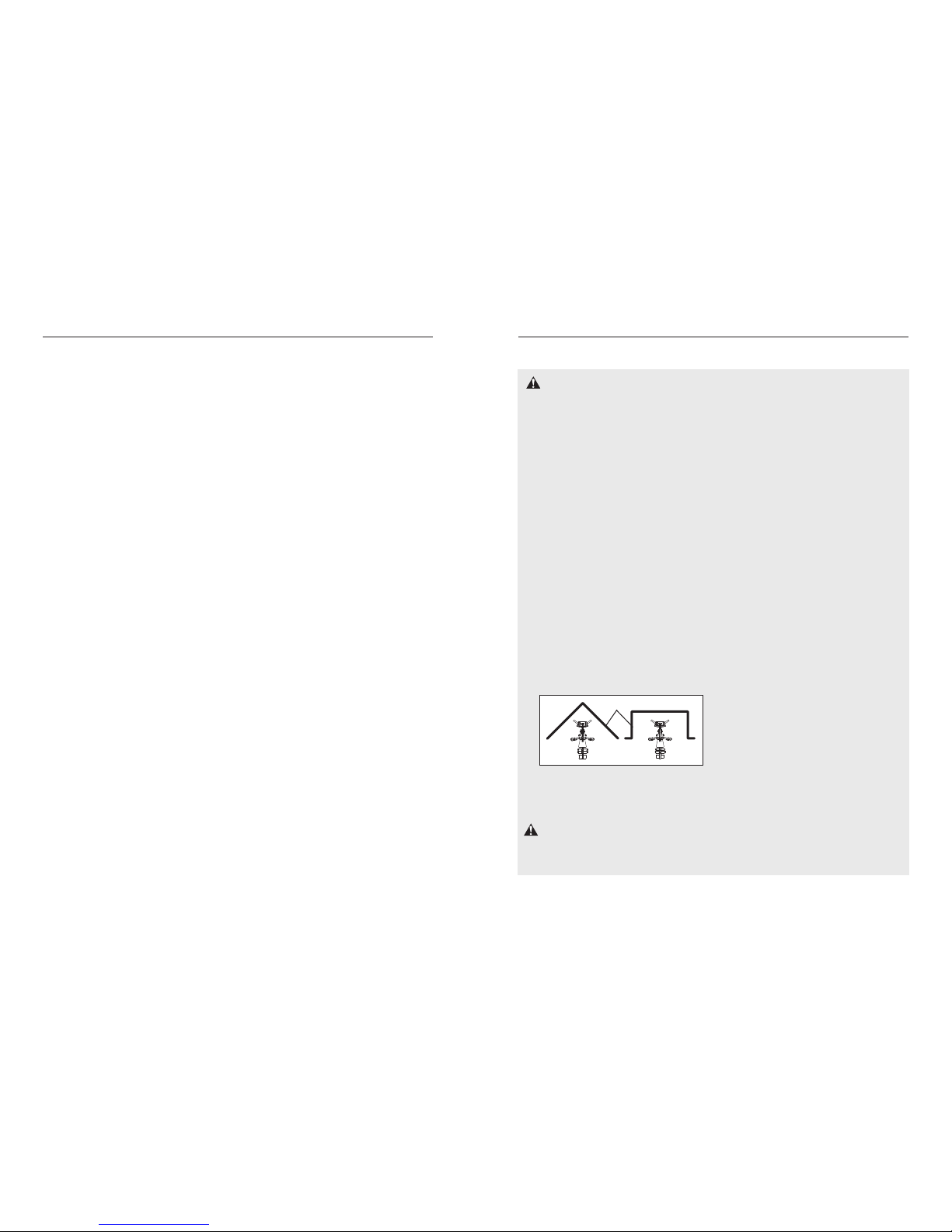
5. This weight system has an open weight
stack; the weight stack must not be access-
able from any point outside of the user’s field
of view. To prevent access to the weight
stack, place the weight system in a corner or
bay of a room, as shown in the drawing
below. There must be no more than 1 meter
(3 ft. 4 in.) of clearance between the weight
system and the adjacent walls.
6. Keep children under 12 and pets away from
the weight system at all times.
7. Keep hands and feet away from moving parts.
8. Inspect and properly tighten all parts regular-
ly. Replace any worn parts immediately.
9. Make sure that the cables remain on the pul-
leys at all times. If the cables bind as you are
exercising, stop immediately and make sure
that the cables are on the pulleys. Replace all
cables at least every two years.
10. Always wear athletic shoes for foot protec-
tion while exercising.
11. Always stand on the foot plate when per-
forming an exercise that could cause the
weight system to tip.
12. The weight system is designed to support a
maximum user weight of 135 kg (300 lbs.).
13. The weight system is designed to be used
only with the included weight. Do not use the
weight system with dumbbells or any other
type of weight to increase the resistance.
14. Always move the seat frame out of the way
when performing squat exercises.
15. Never release the ankle strap, leg lever,
squat bar, leg press, or handles while
weights are raised; the weights will fall with
great force.
16. Do not use the weight system with the top
weight pinned in an elevated position.
17. Always secure the weight stack with the lock
pin and lock after exercising to prevent
unauthorised use of the weight system (see
LOCKING THE WEIGHT STACK on page 15).
18. If you feel pain or dizziness at any time while
exercising, stop immediately and begin cool-
ing down.
WARNING: Before beginning this or any exercise program, consult your physician. This
is especially important for persons over the age of 35 or persons with pre-existing health problems.
Read all instructions before using. ICON assumes no responsibility for personal injury or property
damage sustained by or through the use of this product.
WARNING: To reduce the risk of serious injury, read the following important precautions
before using the weight system.
IMPORTANT PRECAUTIONS
3
Wall

17
WEIGHT RESISTANCE CHART
The chart below shows the approximate weight resistance for the 12.5 lb. (5.67 kg.) weights. Weight resistance
shown is for each arm. Note: The actual resistance at each station may vary due to differences in individ-
ual weight plates as well as friction between the cables, pulleys, and weight guides.
(Note: 1 lb. = 0.454 kg.)
WEIGHT 12345678910 11 12
RESISTANCE 14 23 32 41 50 59 68 77 86 95 102 110
4
Pulley Housing
Shroud
Handle
Weight Pin
Weight Stack
Right Side
Left Side
Note: The terms “right side” and “left side”
are determined relative to a person sitting on
the bench; they do not correspond to right
and left on the drawings in the manual.
Backrest
Swivel Arm
Anchor Hole*
Base
Leg Lever
Seat
BEFORE YOU BEGIN
Thank you for selecting the versatile WEIDER®PRO
5000 weight system. The weight system offers a selec-
tion of weight stations designed to develop every
major muscle group of the body. Whether your goal is
to tone your body, build dramatic muscle size and
strength, or improve your cardiovascular system, the
weight system will help you to achieve the specific
results you want.
For your benefit, read this manual carefully before
using the weight system. If you have questions after
reading this manual, see the front cover of this manu-
al. To help us assist you, please note the product
model number and serial number before calling. The
model number is WEEVSY2985.0. The serial number
can be found on a decal attached to the weight system
(see the front cover of this manual).
Before reading further, please review the drawing
below and familiarise yourself with the parts that are
labelled.
ASSEMBLED DIMENSIONS:
Height: 82 in. / 208 cm
Width: 105 in. / 267 cm
Depth: 94 in. / 239 cm
*Use the anchor holes
to secure the weight
bench in a fixed posi-
tion, if desired.

16
The cable diagram shows the proper routing of
the Press Arm Cable (30). Use the diagram to
make sure that the Cable has been assembled
correctly. If the Cable has not been correctly
routed, the weight system will not function prop-
erly and damage may occur. The numbers show
the correct route for the Cable.
CABLE DIAGRAM
1
2
3
Press Arm Cable (30)
4
6
5
7
8
9
5
ASSEMBLY
Before beginning assembly, carefully read the
following information and instructions:
•Assembly requires two people.
•Because of its weight and size, the weight sys-
tem should be assembled in the location where it
will be used. Make sure that there is enough
clearance to walk around the weight system as
you assemble it.
•Place all parts in a cleared area and remove the
packing materials. Do not dispose of the packing
materials until assembly is completed.
•Tighten all parts as you assemble them, unless
instructed to do otherwise.
•As you assemble the weight system, make sure
all parts are oriented as shown in the drawings.
• For help identifying small parts, use the PART
IDENTIFICATION CHART.
Assembly may be require the included grease
and hex key , and the following tools
(not included):
•Two adjustable spanners
• One rubber mallet
• One standard screwdriver
• One Phillips screwdriver
• Clear tape or masking tape, and soapy water.
Assembly will be more convenient if you have a
socket set, a set of open-end or closed-end span-
ners, or a set of ratchet spanners.
Make Things Easier for Yourself
Everything in this manual is designed to ensure
that the weight system can be assembled suc-
cessfully by almost anyone. However, the weight
system has many parts and the assembly
process will take time. By setting aside plenty of
time, assembly will go smoothly.
1.
Attach the Rear Stabiliser (5) to the Base (1) with
the two M8 x 76mm Carriage Bolts (59) and two
M8 Nylon Locknuts (74).
See the inset drawing. Press the two Base Caps
(38) onto the Base (1).
1
1
1
559
74
38
38
74
Before beginning assembly, make sure you
understand the information in the box
above. For help identifying small parts, use
the PART IDENTIFICATION CHART in the
centre of this manual.
34 37
37
37
731
31
ATTACHING THE LEG LEVER
To use the Leg Lever (7), first attach the seat to the
resistance system (see ADJUSTING THE SEAT
FRAME HEIGHT on page 15). Then, attach the pulley
housings to the low pulley station (see ATTACHING
THE PULLEY HOUSINGS on page 14). Finally, attach
the Extension Cables (31) to an Extension Strap (34)
with two Cable Clips (37) and attach the Extension
Strap to the Leg Lever with another Cable Clip. Adjust
the Extension Strap to the correct length. Note: For
less resistance, the Leg Lever can be used with
only one Extension Cable attached to it.

15
ADJUSTING THE SEAT FRAME HEIGHT
To adjust the height of the Seat Frame (6), or to
remove it for exercising with the squat bar, unhook
the Seat Frame from the indicated brackets on the
Upright (3). Hook it onto the other bracket or set it
aside.
CHANGING THE WEIGHT SETTING
To change the setting of a weight stack, insert the
Weight Pin (55) under the desired Weight (17). Insert
the Weight Pin so that the bent end touches the
weight stack. Turn the bent end down.
See the WEIGHT RESISTANCE CHART on page 17
for the resistance for each station.
LOCKING THE WEIGHT STACK
To lock the weight stack, insert the Lock Pin (53) into
the indicated hole in a Weight Guide (10). Insert the
Lock (52) through the hole in the Weight Pin and
close the Lock.
6
3
55
17
Brackets
53
52
10
Hole
6
2. Press the 110mm Round Inner Cap (42) into the
Upright (3).
Set the Upright (3) onto the Base (1). Have a sec-
ond person hold the Upright until this step is com-
pleted.
Attach the Upright (3) to the Base (1) with the
three M8 x 45mm Bolts (57), three M8 Nylon
Locknuts (74), and four M10 x 25mm Screws (58).
3. Attach the Base Plate (2) to the Base (1) with the
four M4 x 40mm Screws (46), and two M4 x
64mm Screws (81).
2
3
42
58
58
57
57
74
74 1
3
1
81
81
46
2
46
46

This section explains how to adjust the weight system. See the EXERCISE GUIDELINES on page 18 for impor-
tant information about how to get the most benefit from your exercise program. Also, refer to the accompanying
exercise guide to see the correct form for each exercise.
Make sure all parts are properly tightened each time the weight system is used. Replace any worn parts immedi-
ately. The weight system can be cleaned with a damp cloth and a mild, non-abrasive detergent. Do not use sol-
vents.
14
ATTACHING THE PULLEY HOUSINGS
To use a high pulley, slide the hook on the Pulley
Housing (32) onto an Eyehook (66) on the Top Frame
(4). Attach the end of the Extension Cable (31) with-
out the ball to the end of the Press Arm Cable (30)
with a Cable Clip (37). Attach the other Pulley
Housing (32) in the same manner.
See the inset drawing A. To use the leg lever (not
shown), hook the Pulley Housings (32) to the hooks
on the Upright (3).
See the inset drawing B. To use the squat bar (not
shown), hook the Pulley Housings (32) to the hooks
on the sides of the Base (1). Note: To use the squat
bar, you must first remove the Seat Frame from
the Upright (See ADJUSTING THE SEAT FRAME
HEIGHT on the next page).
Remove the Pulley Housings (32) when not in use.
37
37
To attach a Handle (33), first attach the pulley housings
to the weight system (see ATTACHING THE PULLEY
HOUSINGS above). Then, attach the Handle to an
Extension Cable (31) with a Cable Clip (37).
The Ankle Strap (not shown) can be attached to an
Extension Cable (31) or the Press Arm Cable (30) with
a Cable Clip (37).
33
31
30
ADJUSTMENTS
7
4. Insert the Weight Tube (11) into a Weight (17).
Make sure the indicated slot in the Weight is
oriented as shown. Centre the Roll Pin (54) into
the indicated hole in the Weight Tube. Note: The
Roll Pin must be below the Weight.
4
11
54
17
Slot
5. Orient the two Weight Guides (10) with the indi-
cated hole closer to the bottom (see the inset
drawing).
Insert the two Weight Guides (10) into the indicat-
ed holes in the Base (1). Attach the Weight
Guides with two M8 x 115mm Bolts (76), four M8
Washers (72), two 38mm Spacers (48), and two
M8 Nylon Locknuts (74).
Slide the two Weight Bumpers (50) onto the
Weight Guides (10). Next, slide eleven Weights
(17) onto the Weight Guides one at a time. Make
sure the indicated slot in each Weight is ori-
ented as shown. Then, slide the Weight Tube
(11) and Weight (17) onto the Weight Guides.
510
10
17
Slot
Hole
17
50
74
72
1
48
72
76
11
32 66 4
32
31
37
30
32
B
1
32
A3

13
20. Attach the Seat (19) to the Seat Frame (6) with
two M6 x 16mm Screws (60), an M6 x 77mm
Screw (68), and an M6 Washer (78).
Hook the Seat Frame (6) onto the Upright (3) at
the indicated location.
22. Slide two Foam Pads (21) onto the Seat Frame
(6).
Slide a Pad Tube (20) through a hole in the Leg
Lever (7). Slide two Foam Pads (21) onto the Pad
Tube.
23. Make sure that all parts have been properly
tightened before the resistance system is
used.
21. Attach the Bumper (49) to the Leg Lever (7) with
the M4 x 16mm Screw (70).
Apply grease to an M10 x 71mm Bolt (67). Attach
the Leg Lever (7) to the Seat Frame (6) with the
Bolt and an M10 Nylon Locknut (73). Do not
overtighten the Bolt; the Leg Lever must be
able to pivot easily.
20
21
22
19
6
68
6
73
67
Grease
7
70
49
21
20
21
21
21
7
6
78 60
3
8
6. Slide an M6 Washer (78) onto the M6 x 127mm
Screw (79) and insert the Screw into the Upright
(3) through the indicated hole.
Set the Shroud (13) onto the Base (1). Attach the
Bottom Cover (14) and the Shroud to the Base
with two M4 x 16mm Screws (70).
7. Slide the Top Frame (4) onto the Weight Guides
(10). Attach the Top Frame to the Weight Guides
with two M8 x 89mm Bolts (64), four M8 Washers
(72), two 25mm Spacers (47), and two M8 Nylon
Locknuts (74). Do not tighten the Locknuts.
Attach the Top Frame (4) to the Upright (3) with
four M10 x 25mm Screws (58). Do not tighten
the Screws.
Attach the Top Cover (15) to the Shroud (13) and
Top Frame (4) with two M4 x 16mm Screws (70).
Tighten the two M8 Nylon Locknuts (74) and
the four M10 x 25mm Screws (58).
Attach the two Eyehooks (66) to the Top Frame
(4) with two M8 Washers (72) and two M8 Nylon
Locknuts (74). Do not overtighten the
Locknuts; the Eyehooks must rotate freely.
6
79
313
14 70
1
70
78
764
72
47
72
74
4
58
66
66
72
72
74
74
13
10
58
3
70
70
15

12
17. Attach a 2 3/4” Pulley (23) to the right Press Arm
(8) with an M10 x 53mm Button Bolt (61), two
M10 Washers (71), two 5mm Spacers (25), two
Finger Guards (27), and an M10 Nylon Locknut
(73). See the inset drawing. Orient the finger
guards and pulley as shown. Make sure the
Press Arm Cable (30) is in the groove of the
Pulley.
19. Attach the Backrest (18) to the Upright (3) with
the two M6 x 16mm Screws (60) and the M6 x
127mm Screw (79).
18. Make sure the Press Arm Cable (30) is routed
under the indicated welded rods.
Attach a “V”-pulley (22) to the Swivel Arm (16)
with an M10 x 64mm Button Bolt (75), two M10
Washers (71), two 5mm Spacers (25), and an
M10 Nylon Locknut (73).
17
18
73
30
71
71
61
8
75
71
16
71
73
25
25
30
22
25
27
23 27
25
19
79
60
60
18
3
Welded
Rods
27 27
25
9
8. Attach the Press Arm (8) without the wire to the
Upright (3) with four M10 x 25mm Screws (58).
Remove the M4 x 5mm Screw (69) and the
Swivel Arm (16). Route the Press Arm Cable (30)
through the Swivel Arm and the Press Arm (8) as
shown.
Reattach the Swivel Arm (16) to the Press Arm
(8) with the M4 x 5mm Screw (69).
10. Attach a 2 3/4” Pulley (23) to the left Press Arm
(8) with an M10 x 53mm Button Bolt (61), two
M10 Washers (71), two 5mm Spacers (25), two
Finger Guards (27), and an M10 Nylon Locknut
(73). See the inset drawing. Orient the finger
guards and pulley as shown. Make sure the
Press Arm Cable (30) is in the groove of the
Pulley.
9. Attach a “V”-pulley (22) to a Swivel Arm (16) with
an M10 x 64mm Button Bolt (75), two M10
Washers (71), two 5mm Spacers (25), and an
M10 Nylon Locknut (73). Make sure the Press
Arm Cable (30) is routed under the indicated
welded rods.
8
9
10
8
3
30
25
25
75
16
71
71
Welded
Rod
Welded
Rod
73
22
58
58
69
30
16
30
27
27
25
25
8
23
73
71
71
61
27 27
23

11
14. Wrap the Press Arm Cable (30) over a 3 1/2”
Pulley (24). Attach the Pulley and a Cable Trap
(28) to the Top Frame (4) with an M10 x 45mm
Bolt (65) and an M10 Nylon Locknut (73). Make
sure the Cable Trap is oriented to hold the
Cable in the groove of the Pulley.
16. Attach the Press Arm (8) with the wire to the
Upright (3) with four M10 x 25mm Screws (58).
Remove the M4 x 5mm Screw (69) and the
Swivel Arm (16).
Using the wire that is inserted into the Press Arm
(8), route the Press Arm Cable (30) through the
Press Arm as shown. Route the Cable through
the Swivel Arm (16).
Attach the Swivel Arm (16) to the Press Arm (8)
with the M4 x 5mm Screw (69).
15. Route the Press Arm Cable (30) through the Top
Cover (15).
Wrap the Press Arm Cable (30) over a 3 1/2”
Pulley (24). Attach the Pulley and a Cable Trap
(28) to the Top Frame (4) with an M10 x 45mm
Bolt (65) and an M10 Nylon Locknut (73). Make
sure the Cable Trap is oriented to hold the
Cable in the groove of the Pulley.
14
15
16
65
73
24 4
4
28
30
73
24 30 15
58
69
16
8
3
58
30
28
65
10
11. Wrap the Press Arm Cable (30) around a 3 1/2”
Pulley (24) and route the Cable through the Top
Cover (15) as shown.
Attach the 3 1/2” Pulley (24) and a Cable Trap
(28) to the Top Frame (4) with an M10 x 45mm
Bolt (65) and an M10 Nylon Locknut (73). Make
sure the Cable Trap is oriented to hold the
Press Arm Cable (30) in the groove of the
Pulley.
13. Wrap the Press Arm Cable (30) under a 3 1/2”
Pulley (24). Attach the Pulley, a Cable Trap (28),
and two Half Finger Guards (26) to the Weight
Tube (11) with an M10 x 48mm Bolt (62) and an
M10 Nylon Locknut (73) at the indicated hole.
Make sure the Finger Guards are oriented as
shown and are on the outside of the Weight
Tube. Make sure the Cable Trap is oriented to
hold the Cable in the groove of the Pulley.
12. Wrap the Press Arm Cable (30) over a 3 1/2”
Pulley (24). Attach the Pulley and a Cable Trap
(28) to the Top Frame (4) with an M10 x 45mm
Bolt (65) and an M10 Nylon Locknut (73). Make
sure the Cable Trap is oriented to hold the
Cable in the groove of the Pulley.
11
12
13
28
24
30
73 65
65
30
4
28
24
73
15
4
30
26
28
73
11
62
26 24

PART LIST—Model No. WEEVSY2985.0 R0805A
Key No. Qty. Description Key No. Qty. Description
1 1 Base
2 1 Base Plate
3 1 Upright
4 1 Top Frame
5 1 Rear Stabiliser
6 1 Seat Frame
7 1 Leg Lever
8 2 Press Arm
9 1 Squat Bar
10 2 Weight Guide
11 1 Weight Tube
12 1 Weight Tube Bumper
13 1 Shroud
14 1 Bottom Cover
15 1 Top Cover
16 2 Swivel Arm
17 12 Weight
18 1 Backrest
19 1 Seat
20 1Pad Tube
21 4Foam Pad
22 2 “V”-pulley
23 42 3/4” Pulley
24 5 3 1/2” Pulley
25 8 5mm Spacer
26 2Half Finger Guard
27 4 Finger Guard
28 5 Cable Trap
29 4 Pulley Cover
30 1 Press Arm Cable
31 2 Extension Cable
32 2Pulley Housing
33 2Handle
34 2 Extension Strap
35 1 Squat Bar Pad
36 1 Ankle Strap
37 6 Cable Clip
38 2Base Cap
39 4 64mm Round Outer Cap
40 4 19mm Round Inner Cap
41 2 51mm Round Inner Cap
42 1110mm Round Inner Cap
43 2 Press Arm Cap
44 2 32mm Round Inner Cap
45 1 51mm x 76mm Inner Cap
46 4 M4 x 40mm Screw
47 2 25mm Spacer
48 2 38mm Spacer
49 1 Bumper
50 2 Weight Bumper
51 4 Swivel Arm Bushing
52 1 Lock
53 1 Lock Pin
54 1 Roll Pin
55 1 Weight Pin
56 2 25mm Round Inner Cap
57 3 M8 x 45mm Bolt
58 16 M10 x 25mm Screw
59 2 M8 x 76mm Carriage Bolt
60 4 M6 x 16mm Screw
61 2 M10 x 53mm Button Bolt
62 1 M10 x 48mm Bolt
63 2 51mm Thin Round Inner Cap
64 2M8 x 89mm Bolt
65 4 M10 x 45mm Bolt
66 2Eyehook
67 1 M10 x 71mm Bolt
68 1 M6 x 77mm Screw
69 2M4 x 5mm Screw
70 5 M4 x 16mm Screw
71 12 M10 Washer
72 10 M8 Washer
73 12 M10 Nylon Locknut
74 11 M8 Nylon Locknut
75 2M10 x 64mm Button Bolt
76 2M8 x 115mm Bolt
77 2 M5 x 15mm Screw
78 2 M6 Washer
79 1 M6 x 127mm Screw
80 2 M10 x 50mm Button Bolt
81 2M4 x 64mm Screw
82 1 Squat Bar Hook
# 1 User’s Manual
# 1 Exercise Guide
#1Hex Key
Note: “#” indicates a non-illustrated part. Specifications are subject to change without notice.
M6 Washer (78)
M8 Washer (72)
M10 x 45mm Bolt (65)
M6 x 127mm Screw (79)
M8 x 76mm Carriage Bolt (59)
M6 x 16mm Screw (60)
M10 x 25mm Screw (58)
M4 x 40mm Screw (46)
M8 x 45mm Bolt (57)
M10 x 71mm Bolt (67)
M10 x 64mm Button Bolt (75)
M10 x 48mm Bolt (62)
M6 x 77mm Screw (68)
M8 x 89mm Bolt (64)
M8 x 115mm Bolt (76)
M10 Nylon Locknut (73)
M10 Washer (71)
M8 Nylon Locknut (74)
M4 x 64mm Screw (81)
M4 x16mm Screw (70)
M10 x 53mm Button Bolt (61)
PART IDENTIFICATION CHART
Refer to the drawings below to identify small parts used in assembly. The number in parentheses by each draw-
ing is the key number of the part, from the PART LIST in the centre of this manual. Note: Some small parts
may have been pre-attached. If a part is not in the parts bag, check to see if it has been pre-attached.

72
64
72
47
74
10
53
52
76
72
48
72
74
73
62
54
26
26
24
11
12
17
55
50
30
22
25 25
73
75
16
51
43
869
58
61
58
73
25
23
27
27
60
79
78
58
14 70
70
13
70
15
70
45
24 28
65
73
4
24
28
65
28
24
73
74
72
74
72
39
39
66
66
73
32
7180
73
32
29
29
31
31
23
23
58 42
3
27
25
23
27
58
73
61
58
69
43
51
16
73
75
25
22
30
25
57
57
81
81
74
74
8
24 28
65
71
71
71
71
56
56
29
71
71
71
71
71
71
71
28
EXPLODED DRAWING—Model No. WEEVSY2985.0 R0805A
34
59
5
39
39
74
74
58
58
1
46
38
46
38
2
36
37
35
44
44
18
19
33
40 21
41
63
67 6
7
40
63
40
40
21
21
21
41
73
49 70
20
60
78
68
77
46
46
9
82
EXPLODED DRAWING—Model No. WEEVSY2985.0 R0805A
Table of contents
Other WeiderPro Fitness Equipment manuals

WeiderPro
WeiderPro 205 User manual

WeiderPro
WeiderPro WEEVSY59230 User manual

WeiderPro
WeiderPro weiderpro 9930 User manual

WeiderPro
WeiderPro 125 User manual

WeiderPro
WeiderPro WEEVBE1495.0 User manual

WeiderPro
WeiderPro 7500 User manual

WeiderPro
WeiderPro 445 WEEVBE3295.0 User manual

WeiderPro
WeiderPro 255 L User manual

WeiderPro
WeiderPro 831.14934.0 User manual

WeiderPro
WeiderPro 355 User manual