Weller HAP 200 User manual

EN FR IT ES PT NL SV DK FI GR TR CZ PL HU SK SL EE LV LT DE
HAP 200
Betriebsanleitung

HAP 200
HAP 200
Geräteübersicht
1 Elektrisches Anschlusskabel
2 Anschluss Heißluftschlauch
3 Fingerschalter
4 Ablage
5 Düsenadapter
6 Düse
356
1
2
4

HAP 200 3-6
DE
DE
FR IT ES PT NL SV DK FI GR TR CZ PL HU SK SL EE LV LT
Inhalt
1Zu dieser Anleitung .................................................................... 3
2Zu Ihrer Sicherheit ..................................................................... 3
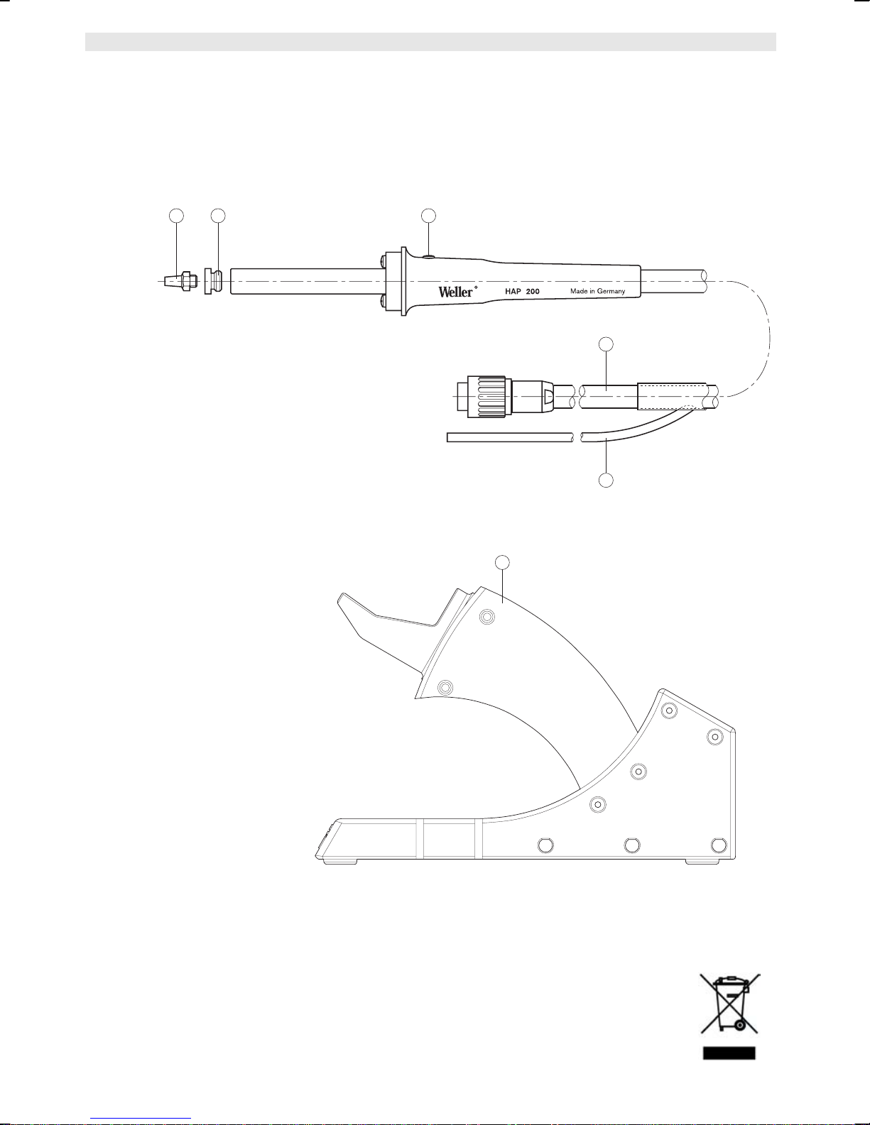
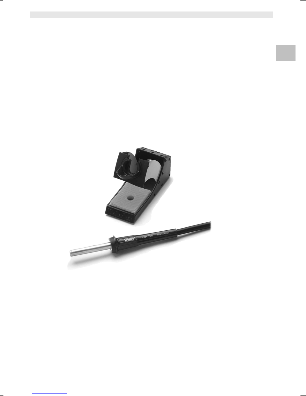
3Lieferumfang .............................................................................. 4
4Gerätebeschreibung .................................................................. 5
5Inbetriebnahme des Geräts ....................................................... 5
6Zubehör ..................................................................................... 6
7Entsorgung ................................................................................ 6
8Garantie ..................................................................................... 6
1Zu dieser Anleitung
Wir danken Ihnen für das mit dem Kauf des Weller Heißluftkolbens
HAP 200 erwiesene Vertrauen. Bei der Fertigung wurden strengste
Qualitätsanforderungen zugrunde gelegt, die eine einwandfreie
Funktion des Gerätes sicherstellen.
Diese Anleitung enthält wichtige Informationen, um den HAP 200
sicher und sachgerecht in Betrieb zu nehmen, zu bedienen, zu
warten und einfache Störungen selbst zu beseitigen.
ZLesen Sie diese Anleitung und die beiliegenden
Sicherheitshinweise vor Inbetriebnahme des HAP 200 vollständig
durch, bevor Sie mit dem HAP 200 arbeiten.
ZBewahren Sie diese Anleitung so auf, dass sie für alle Benutzer
zugänglich ist.
1.1 Berücksichtigte Richtlinien
Der Weller Heißluftkolben HAP 200 entspricht den Angaben der EG
Konformitätserklärung mit den Richtlinien 2004/108/EG und
2006/96/EG.
1.2 Zu beachtende Dokumente
−Betriebsanleitung des HAP 200
−Begleitheft Sicherheitshinweise zu dieser Anleitung
−Betriebsanleitung Ihres Steuergeräts
2Zu Ihrer Sicherheit
Der Heißluftkolben HAP 200 wurde entsprechend dem heutigen
Stand der Technik und den anerkannten sicherheitstechnischen
Regeln hergestellt. Trotzdem besteht die Gefahr von Personen- und
Sachschäden, wenn Sie die Sicherheitshinweise im beiliegenden
Sicherheitsheft sowie die Warnhinweise in dieser Anleitung nicht
beachten. Geben Sie den HAP 200 an Dritte stets zusammen mit
der Betriebsanleitung weiter.

4-6 HAP 200
2.1 Das müssen Sie beachten
−Legen Sie den Heißluftkolben stets in der Originalablage ab.
−Entfernen Sie alle brennbaren Gegenstände aus der Nähe des
heißen Lötwerkzeugs.
−Schließen Sie niemals brennbare Gase an Ihre Heißluftgeräte an.
−Tragen Sie geeignete Schutzkleidung beim Betrieb des HAP 200.
−Richten Sie den Heißluftstrahl nicht auf Personen und schauen
Sie nicht in den Heißluftstrahl hinein.
−Lassen Sie den heißen HAP 200 nie unbeaufsichtigt.
−Arbeiten Sie nicht an unter Spannung stehenden Teilen.
−Sorgen Sie bei der Verwendung von inerten Gasen für
ausreichende Belüftung.
−Beachten Sie die Betriebsanleitung Ihres Steuergeräts.
2.2 Bestimmungsgemäßer Gebrauch
Verwenden Sie den HAP 200 ausschließlich gemäß dem in der
Betriebsanleitung angegebenen Zweck zum Löten und Entlöten von
oberflächenmontierten Bauelementen unter den hier angegebenen
Bedingungen. Der bestimmungsgemäße Gebrauch des HAP 200
schließt auch ein, dass
−Sie diese Anleitung beachten,
−Sie alle weiteren Begleitunterlagen beachten,
−Sie die nationalen Unfallverhütungsvorschriften am Einsatzort
beachten.
Für andere von der Betriebsanleitung abweichende Verwendung,
sowie bei eigenmächtig vorgenommenen Veränderungen am Gerät
wird vom Hersteller keine Haftung übernommen.
3Lieferumfang
−Heißluftkolben HAP 200
−Betriebsanleitung
−Heft Sicherheitshinweise
−Ablage WDH 30
−Düse R06 Ø 3,0 mm
−Steckschlüssel für Normaldüse
−Düsenadapter M6
−Gabelschlüssel SW8

HAP 200 5-6
DE DE FR IT ES PT NL SV DK FI GR TR CZ PL HU SK SL EE LV LT
4Gerätebeschreibung
Der Weller Heißluftkolben HAP 200 mit integriertem
Fingerschalter (3) eignet sich zum Löten und Entlöten von
oberflächenmontierten Bauelementen. Ein breites Düsenprogramm
macht ihn universell einsetzbar. Durch den im Handgriff integrierten
Fingerschalter (3) wird der Luftdurchfluss gesteuert. Die Ionenfalle
im Kolben sorgt dafür, dass die ausströmende Heißluft frei von
statischen Ladungen ist. Schlauch und Handgriff sind antistatisch
ausgeführt. Die Temperatur der Heißluft kann über das Steuergerät
im Bereich von 50 °C – 550 °C (100 °F – 1000 °F) eingestellt
werden.
4.1 Technische Daten HAP 200
Heizleistung 200 W
Heizspannung 24 V
A
C
Max. Luftmenge 15 l/min
Temperaturbereich 50 °C bis 550 °C/100 °F bis 1000 °F
Temperaturgenauigkeit ±30
°C/±80 °F
Potentialausgleich
Der Heißluftkolben HAP 200 ist mit einer Potentialausgleichsleitung
ausgestattet, die gemäß der Betriebsanleitung des verwendeten
Steuergeräts beschaltet werden kann.
5Inbetriebnahme des Geräts
WARNUNG!
Verletzungsgefahr durch Heißluft und inerte Gase.
Beim Betrieb des Heißluftkolbens besteht Verbrennungsgefahr
durch austretende Heißluft. Vorsicht: Bei Verwendung von inerten
Gasen besteht Erstickungsgefahr.
ZLesen Sie die beiliegenden Sicherheitshinweise, die
Sicherheitshinweise in dieser Betriebsanleitung sowie die
Anleitung Ihres Steuergeräts vor in Inbetriebnahme des
HAP 200 vollständig durch. Beachten Sie die darin gegebenen
Vorsichtsmaßnahmen.
1. Den Heißluftkolben HAP 200 sorgfältig auspacken.
2. Sicherstellen, dass das Steuergerät ausgeschaltet ist.
3. Den Heißluftkolben HAP 200 in der Sicherheitsablage (4)
ablegen.
4. Den elektrischen Anschlussstecker (1) des HAP 200 in die
7-polige Anschlussbuchse des Steuergeräts einstecken und
durch kurze Rechtsdrehung verriegeln.
5. Die Schlauchleitung des HAP 200 (2) auf den „Air"-Nippel des
Steuergeräts schieben.

6-6 HAP 200
6. Steuergerät am Netzschalter einschalten und Temperatur und
Luftdurchflussmenge einstellen.
Beachten Sie hierbei die Betriebsanleitung Ihres Steuergeräts.
5.1 Arbeitshinweise
VORSICHT!
Beschädigung des Kolbenheizkörpers durch zu
langes Düsengewinde.
Die Gewindetiefe für Heißluftdüsen beträgt max. 5 mm (0,2 "). Ein
längeres Gewinde führt zur Zerstörung des Heizkörpers.
Die Verwendung von Düsen anderer Hersteller als Weller kann zu
Schäden am Heißluftkoben führen. Hierbei erlischt der
Garantieanspruch.
ZAchten Sie auf die richtige Gewindetiefe der
einzuschraubenden Düsen!
ZVerwenden Sie Weller Originalheißluftdüsen!
Mit dem HAP 200 erhalten Sie einen SW8 Steckschlüssel. Dieser
muss verwendet werden, um die Düsen zu wechseln. Ziehen Sie die
Muttern am Heizkörper mit dem mitgelieferten Maulschlüssel fest.
Hinweis Wenn Sie den mitgelieferten Düsenadapter (5) (005 87 610 28) mit
dem SW8 Steckschlüssel in den HAP 200 einschrauben, können
Sie die gleichen Düsen wie für den HAP 1 verwenden.
Ersatzheißluftkolben sind justiert und können ohne Nachjustierung
angeschlossen und verwendet werden.
Zur Überprüfung der Heißlufttemperatur wird die Verwendung einer
speziellen Messdüse (005 87 278 08) empfohlen, durch die ein
Mantelthermoelement (Ø 0,5 mm) kontaktiert werden kann.
6Zubehör
HAP 200 Heißluftdüsen (siehe Überblick Hot Air Nozzles).
7Entsorgung
Entsorgen Sie ausgetauschte Geräteteile, Filter oder alte Geräte
gemäß den Vorschriften Ihres Landes.
8Garantie
Die Mängelansprüche des Käufers verjähren in einem Jahr ab
Ablieferung an ihn. Dies gilt nicht für Rückgriffsansprüche des
Käufers nach §§ 478, 479 BGB.
Aus einer von uns abgegebenen Garantie haften wir nur, wenn die
Beschaffenheits- oder Haltbarkeitsgarantie von uns schriftlich und
unter Verwendung des Begriffs „Garantie“ abgegeben worden ist.
Technische Änderungen vorbehalten!
Die aktualisierten Betriebsanleitungen finden Sie unter
www.weller-tools.com.

EN
FR IT ES PT NL SV DK FI GR TR CZ PL HU SK SL EE LV LT DE
HAP 200
Operating Instructions

HAP 200
HAP 200
Device overview
1 Connector with cable
2 Hot air hose connection
3 Push button
4 Stand
5 Nozzle adaptor
6 Nozzle
356
1
2
4

HAP 200 3-7
DE EN FR IT ES PT NL SV DK FI GR TR CZ PL HU SK SL EE LV LT
Contents
1About these instructions ............................................................ 3
2For your safety ........................................................................... 3
3Scope of supply ......................................................................... 4
4Device description ..................................................................... 5
5Commissioning the device ......................................................... 5
6Accessories ............................................................................... 6
7Disposal ..................................................................................... 6
8Warranty .................................................................................... 6
1 About these instructions
Thank you for placing your trust in our company by purchasing the
Weller HAP 200 Hot Air Tool. This product meets or exceeds the
requirements established by Weller for superior performance,
versatility and quality.
These instructions contain important information which will help you
to start up, operate and service the HAP 200 safely and correctly, as
well as to eliminate simple faults/malfunctions yourselves.
ZPlease read these instructions carefully and the attached safety
guidelines before you put the HAP 200 into operation.
ZKeep these instructions in a place that is accessible to all users.
1.1 Directives taken into consideration
The Weller HAP 200 Hot Air Tool corresponds to the EC Declaration
of Conformity in accordance with the basic safety requirements of
Directives 2004/108/EC and 2006/96/EC.
1.2 Applicable documents
−HAP 200 operating instructions
−Accompanying booklet on safety
−Operating instructions for your control unit
2For your safety
The HAP 200 Hot Air Tool has been manufactured in accordance
with state-of-the-art technology and recognized safety rules and
regulations. There is nevertheless the risk of personal injury and
damage to property if you fail to observe the safety information set
out in the enclosed booklet accompanying these operating
instructions and the warnings given therein. Always pass on the
HAP 200 on to third parties along with these operating instructions.
The manufacturer shall not be liable for damage resulting from
misuse of the machine or unauthorized alterations

4-7 HAP 200
−State of California warning:
When used for soldering and similar applications, this product
produces chemicals known to the State of California to cause
cancer and birth defects or other reproductive harm.
2.1 Please observe the following:
−Always place the hot air tool in its original stand.
−Remove all flammable objects from the vicinity of the hot soldering
tool.
−Do not connect flammable gases to your hot air equipment.
−Always wear suitable protective clothing when using the HAP 200.
−Do not direct the hot air jet at persons or look into the hot air jet.
−Never leave the hot HAP 200 unattended.
−Do not carry out work on live parts
−When using inert gases, make sure the area is well ventilated.
−Read and observe the operating instructions of your control unit.
2.2 Intended use
Use the HAP 200 exclusively for the purpose indicated in the
operating instructions of releasing, accommodating and setting down
chip components under the conditions specified here. Intended use
of the HAP 200 also includes that
−you read and follow these instructions,
−you read and follow all additional accompanying documents,
−you observe the national accident-prevention regulations
applicable at the location where the device is used.
The manufacturer accepts no liability for damages resulting from
failure to use the device in compliance with these operating
instructions or unauthorised modifications to the device.
3Scope of supply
−Hot air tool HAP 200
−Operating instructions
−Safety booklet
−Stand WDH 30
−Nozzle R06 Ø 3.0 mm
−Socket wrench for standard nozzle
−Nozzle adaptor M6
−Open-end wrench 8 mm across flats

HAP 200 5-7
DE EN FR IT ES PT NL SV DK FI GR TR CZ PL HU SK SL EE LV LT
4Device description
The Weller HAP 200 Hot Air Tool with integrated finger switch (3) is
suitable for soldering and desoldering surface-mounted components.
A wide range of nozzles adds to the versatility of the HAP 200 tool.
A push button (3) integrated in the handle is used to control the air
flow. The ionising circuit integrated in the tool ensures that hot air is
static free. The hose and handle are of antistatic design.
The hot air temperature can be set to between 50°C and 550°C
(100°F and 1000°F) using the control unit.
4.1 Technical data HAP 200
Heating output 200 W
Heating voltage 24 V AC
Max. air flow rate 15 l/min
Temperature range 50°C up to 550°C/100°F up to
1000°F
Temperature accuracy ±30°C/±80°F
Potential balance
The HAP 200 hot air tool has an equipotential bonding conductor
which can be connected in accordance with the operating
instructions of the control unit in use.
5Commissioning the device
WARNING!
Risk of injury due to hot air and inert gases.
Use caution when operating the hot air tool, because hot air can
cause burns. Caution: use of inert gases in an enclosed area can
cause asphyxiation.
ZPlease read carefully the safety instructions in the attached
booklet, the safety guidelines given in these operating
instructions and the operating instructions of your control unit
before putting the HAP 200 into operation. Also observe the
safety precautions described herein.
1. Carefully unpack hot air tool HAP 200.
2. Make sure that the control unit is OFF.
3. Place the HAP 200 hot air tool into the stand (4).
4. Insert the electrical connector (1) of the HAP 200 into the 7-pin
terminal jack on the control unit, and lock in place by briefly
twisting clockwise.
5. Push the air hose of the HAP 200 (2) onto the air nipple on the
control unit.
6. Turn on the control unit at the power switch and set the
temperature and air flow. Also read and observe the operating
instructions of your control unit.

6-7 HAP 200
5.1 Operating guidelines
CAUTION!
Excessively long nozzle threads can damage the
heater core of your tool.
The max. thread depth for hot air nozzles is 5 mm (0.2 "). Use of
longer threads will cause irreparable damage to the heater core.
Use of Non-Weller nozzles may result in damage to the hot air
tool and void the warranty.
ZPay attention to the correct thread depth of the screw-in
nozzles!
ZAlways use Weller original hot air nozzles!
The HAP 200 is supplied with an 8 mm socket wrench. Use this to
replace the nozzles. Tighten the nuts on the heater core using the
supplied open-end wrench.
Note If you screw the enclosed nozzle adaptor (5) (005 87 610 28) into
the HAP 200 using the 8 mm socket wrench, you can use the same
nozzles as those for the HAP 1.
Replacement hot air tools are supplied preset and can be connected
and used without any need for readjustment.
To check the hot air temperature, it is recommended that you use a
special test nozzle (005 87 278 08) which mates with a sheathed
thermocouple (Ø 0.5 mm).
6Accessories
HAP 200 Hot Air Nozzles
(see overview Hot Air Nozzles)
7Disposal
Dispose of replaced equipment parts, filters or old devices in
accordance with the rules and regulations applicable in your country.
8Warranty
Claims by the buyer for physical defects are time-barred after a
period of one year from delivery to the buyer. This does not apply to
claims by the buyer for indemnification in accordance with §§ 478,
479 BGB (German Federal Law Gazette).
We shall only be liable for claims arising from a warranty furnished
by us if the quality or durability warranty has been furnished by use
in writing and using the term "Warranty“.

HAP 200 7-7
DE EN FR IT ES PT NL SV DK FI GR TR CZ PL HU SK SL EE LV LT
In addition, for the USA and Canada:
Weller Tools GmbH warrants to the original purchaser and any
subsequent owner (“Buyer”) that Weller soldering and desoldering
products will be free from defects in material and workmanship for a
period of one year from date of purchase, provided that no warranty
is made with respect to products which have been altered, subjected
to abuse or improperly used, installed or repaired. Use of non-Weller
Tools GmbH components will void this warranty if a non-Weller
Tools GmbH component is defective (or is the source of the defect).
Weller Tools GmbH will repair or replace products found to be
defective not caused by a part, component or accessory
manufactured by another company, during the warranty period.
Contact Weller Tools with dated proof of purchase and return to
Apex Tool Group LLC., 14600 York Rd. Suite A, Sparks, MD 21152
USA. All costs of transportation and reinstallation shall be borne by
the Buyer.
IN NO EVENT SHALL WELLER TOOLS GMBH BE LIABLE FOR
INCIDENTAL OR CONSEQUENTIAL DAMAGES. WELLER TOOLS
GMBH LIABILITY FOR ANY CLAIMS ARISING OUT OF THIS
WARRANTY SHALL NOT EXCEED THE PURCHASE PRICE OF
THE PRODUCT.
THE PERIOD OF ALL IMPLIED WARRANTIES APPLICABLE TO
THIS PRODUCT INCLUDING ANY IMPLIED WARRANTY OF
MERCHANTABILITY OR FITNESS, OR FITNESS FOR A
PARTICULAR PURPOSE IS LIMITED TO 12 MONTHS FROM THE
DATE OF PURCHASE BY THE USER.
Some states do not allow the exclusion or limitation of incidental or
consequential damages, so the above limitation or exclusion may
not apply to you. Some states do not allow limitation on how long an
implied warranty lasts, so the above limitation may not apply to you.
This warranty gives you specific legal rights, and you may also have
other rights, which vary from state to state.
Subject to technical alterations and amendments!
See the updated operating instructions at www.weller-tools.com.

EN FR
FR
ES PT NL SV DK FI GR TR CZ PL HU SK SL EE LV LT DE
HAP 200
Model d'emploi

HAP 200
HAP 200
Schéma de l'appareil
1 Connecteur avec câble
2 Flexible d'air chaud
3 Bouton poussoir
4 Support
5 Embout à buse
6 Buse
356
1
2
4

HAP 200 3-7
DE EN FR FR ES PT NL SV DK FI GR TR CZ PL HU SK SL EE LV LT
Table des matières
1A propos de ce manuel .............................................................. 3
2Pour votre sécurité ..................................................................... 4
3Contenu de la livraison .............................................................. 5
4Description de l'outil ................................................................... 5
5Mise en service de l'outil ............................................................ 5
6Accessoires ............................................................................... 6
7Élimination ................................................................................. 6
8Garantie ..................................................................................... 7
1 A propos de ce manuel
Merci de nous avoir accordé votre confiance en achetant l'outil à air
chaud Weller HAP 200.
Ce produit satisfait ou dépasse les exigences établies par Weller en
termes de performance supérieure, de souplesse d'utilisation et de
qualité.
Le présent manuel contient des informations importantes concernant
le démarrage, le fonctionnement et la maintenance du HAP 200 en
toute sécurité, ainsi que la résolution des défauts/
dysfonctionnements simples.
ZVeuillez lire attentivement le présent manuel d'instruction et les
consignes de sécurité en annexe avant de mettre le HAP 200 en
marche.
ZConservez ce manuel d'instruction dans un endroit accessible à
tous les utilisateurs.
1.1 Directives de référence
L'outil à air chaud Weller HAP 200 répond à la déclaration de
conformité CE selon les exigences fondamentales en matière de
sécurité des directives 2004/108/CE et 2006/96CE.
1.2 Documents à suivre
−Manuel d'instruction HAP 200
−Livret annexe sur la sécurité
−Manuel d'instruction de l'unité de commande

4-7 HAP 200
2Pour votre sécurité
−L'outil à air chaud HAP 200 a été fabriqué selon l'état de l'art et
les règles de sécurité reconnues. Toutefois, le non-respect des
consignes de sécurité et des avertissements décrits dans le livret
en annexe au présent manuel d'instruction peut être à l'origine de
risque de dommages corporels et matériels.
−Transmettez à un tiers toujours le HAP 200 accompagné du
présent manuel d'instruction.
−Le fabricant n'est pas responsable quant aux dommages résultant
d'un usage inapproprié de la machine ou de modifications non
autorisées.
−Avertissement de la part de l'État de Californie :
Ce produit, lorsqu'il est utilisé pour le soudage et des
applications similaires, produit des substances chimiques
connues de l'État de Californie pour causer le cancer et des
anomalies congénitales, voire d'autres problèmes de
reproduction.
2.1 Respectez les consignes suivantes :
−Placez systématiquement l'outil à air chaud dans son support
d'origine.
−Éloignez tous les objets inflammables se trouvant à proximité de
l'outil de soudage chaud.
−Ne raccordez pas de gaz inflammable sur votre équipement à air
chaud.
−Portez toujours un vêtement de protection adapté lors de chaque
utilisation du HAP 200.
−Ne dirigez pas le jet d'air chaud vers des personnes et ne
regardez pas à l'intérieur du jet d'air chaud.
−Ne laissez pas le HAP 200 chaud sans surveillance.
−N'exécutez pas les travaux sur des pièces sous tension
−Si vous utilisez des gaz inertes, assurez-vous que la zone est bien
ventilée.
−Lisez et suivez le manuel d'instruction de votre unité de
commande.
2.2 Utilisation conforme
Utilisez le HAP 200 exclusivement aux fins décrites dans le manuel
d'instruction concernant le desserrage, l'insertion et l'abaissement
des composants dans les conditions spécifiées ici. L'utilisation
conforme du HAP 200 inclut également l'obligation de
−lire et suivre le présent manuel d'instruction,
−lire et suivre tous les documents annexes,
−respecter les réglementations nationales concernant la prévention
des accidents en vigueur dans le pays d'utilisation de l'outil.
Le fabricant dénie toute responsabilité pour les dommages résultant
d'une utilisation de l'outil non conforme au présent manuel
d'instruction ou de modifications non autorisées sur l'outil.

HAP 200 5-7
DE EN FR
FR
FR PT NL SV DK FI GR TR CZ PL HU SK SL EE LV LT
3Contenu de la livraison
−Outil à air chaud HAP 200
−Manuel d'instruction HAP
−Livret de sécurité
−Support WDH 30
−Buse R06 Ø 3.0 mm
−Clé à douille pour buse standard
−Embout de buse M6
−Clé plate 8 mm
4Description de l'outil
L'outil à air chaud Weller HAP 200 à bouton poussoir intégré (3)
convient au soudage et au dessoudage des composants montés en
surface. Une large gamme de buses étend la souplesse d'utilisation
du HAP 200.
Un bouton poussoir (3) intégré dans la poignée permet de contrôler
le flux d'air. Le circuit ionisant intégré dans l'outil garantit un air
chaud exempt de champ statique. Le flexible et la poignée sont
antistatiques.
La température de l'air chaud peut être réglée entre 50 °C et 550 °C
(100 °F et 1000 °F) à l'aide de l'unité de commande.
4.1 Caractéristiques techniques du HAP 200
Puissance de chauffage 200 W
Tension de chauffage 24 V CA
Débit d'air max. 15 l/min
Plage de températu
r
e 50 °C à 550 °C
/
100 °F à 1000 °F
Précision de température ±30 °C
/
±80
°F
Liaison équipotentielle
L'outil à air chaud HAP 200 possède un conducteur de liaison
équipotentielle que vous pouvez raccorder conformément au manuel
d'instruction de l'unité de commande utilisée.
5Mise en service de l'outil
AVERTISSEMENT !
Risque de blessure dû à l'air chaud et aux gaz
inertes.
Utilisez l'outil à air chaud avec précaution car l'air chaud peut
brûler. Attention : l'utilisation de gaz inertes dans une pièce close
risque d'asphyxier les personnes présentes.
ZVeuillez lire attentivement les consignes de sécurité contenues
dans le livret en annexe et dans le présent manuel
d'instruction ainsi que le manuel d'instruction de votre unité de
commande avant de mettre le HAP 200 en service. Respectez
également les précautions de sécurité décrites ci-dessous.

6-7 HAP 200
1. Déballez l'outil à air chaud HAP 200 avec précaution.
2. Assurez-vous que l'unité de commande est éteinte.
3. Placez l'outil à air chaud HAP 200 dans son support (4).
4. Branchez le connecteur (1) du HAP 200 dans la prise à
7 broches sur l'unité de commande, puis verrouillez-le en
tournant légèrement vers la droite.
5. Insérez le flexible à air (2) du HAP 200 dans le raccord à air
comprimé sur l'unité de commande.
6. Mettez l'unité de commande en marche en activant l'interrupteur
principal, puis réglez la température et le débit d'air.
Lisez et respectez le manuel d'instruction de votre unité de
commande.
5.1 Consignes d'utilisation
ATTENTION !
Des filets de buse trop longs peuvent endommager
le radiateur de votre outil.
La profondeur max. des filets pour les buses d'air chaud est 5 mm
(0,2 "). L'utilisation de filets plus longs entraînera des dommages
irréparables sur le radiateur.
L'utilisation de buses autres que Weller peut entraîner des
dommages sur l'outil à air chaud et annuler la garantie.
ZPortez une attention particulière à la longueur de filet des
buses !
ZUtilisez toujours des buses à air chaud Weller d'origine !
Le HAP 200 est fourni avec une clé à douille 8 mm. Utilisez-la pour
remplacer les buses. Serrez les écrous du radiateur à l'aide de la clé
plate fournie.
Remarque Si vous vissez l'embout de buse fourni (5) (005 87 610 28) dans le
HAP 200 à l'aide de la clé à douille 8 mm, vous pouvez utiliser les
mêmes buses que celles du HAP 1.
Les outils à air chaud de rechange sont préréglés à la livraison et
donc prêts à être branchés et utilisés sans ajustement
supplémentaire.
Pour vérifier la température de l'air chaud, il est recommandé
d'utiliser une buse test spéciale (005 87 278 08) qui s'accouple sur
un thermocouple gainé (Ø 0.5 mm).
6Accessoires
Buses à air chaud HAP 200
(voir le schéma Buses à air chaud dans la section au verso et sur
www.weller.eu)
7Élimination
Éliminez les pièces remplacées, les filtres ou les appareils usagés
conformément aux règles et réglementations en vigueur dans votre
pays.

HAP 200 7-7
DE EN FR
FR
FR PT NL SV DK FI GR TR CZ PL HU SK SL EE LV LT
8Garantie
Toute réclamation par l'acheteur quant à des défauts physiques est
prescrite après une période d'un an à compter de la date de livraison
chez l'acheteur. Cette limitation ne s'applique pas aux réclamations
formulées par l'acheteur relatives à une indemnisation
conformément aux §§ 478, 479 BGB (Code civil allemand).
Notre responsabilité pour les révendications provient exclusivement
d'une garantie fournie de notre part si la garantie de qualité ou de
durabilité a été fournie par écrit et emploie le terme "Garantie".
Sous réserve de modifications techniques!
Vous trouverez les manuels d'utilisation actualisés sur
www.weller-tools.com.
Other manuals for HAP 200
1
Table of contents
Languages:
Other Weller Soldering Gun manuals

Weller
Weller WXUTS User manual

Weller
Weller wtt 1 User manual

Weller
Weller WSD 151 User manual

Weller
Weller WX1 User manual

Weller
Weller WE1010NA User manual

Weller
Weller WT 1 User manual

Weller
Weller WD 2000 User manual

Weller
Weller LR 21 User manual

Weller
Weller WHA900 User manual

Weller
Weller WE 1 User manual

Weller
Weller WHS M User manual

Weller
Weller WXA 2 User manual

Weller
Weller WSD 81i User manual

Weller
Weller EC1002S User manual

Weller
Weller WAD 101 User manual

Weller
Weller WLC200 User manual

Weller
Weller whs 40d User manual

Weller
Weller T0052921399N User manual

Weller
Weller WSF 81 D5 User manual

Weller
Weller WTBR 1000 User manual