Quick Read
WARNINGS!
TABLE OF
CONTENTS
INTRODUCTION
& WARNINGS
DESCRIPTION
& INSTALLATION
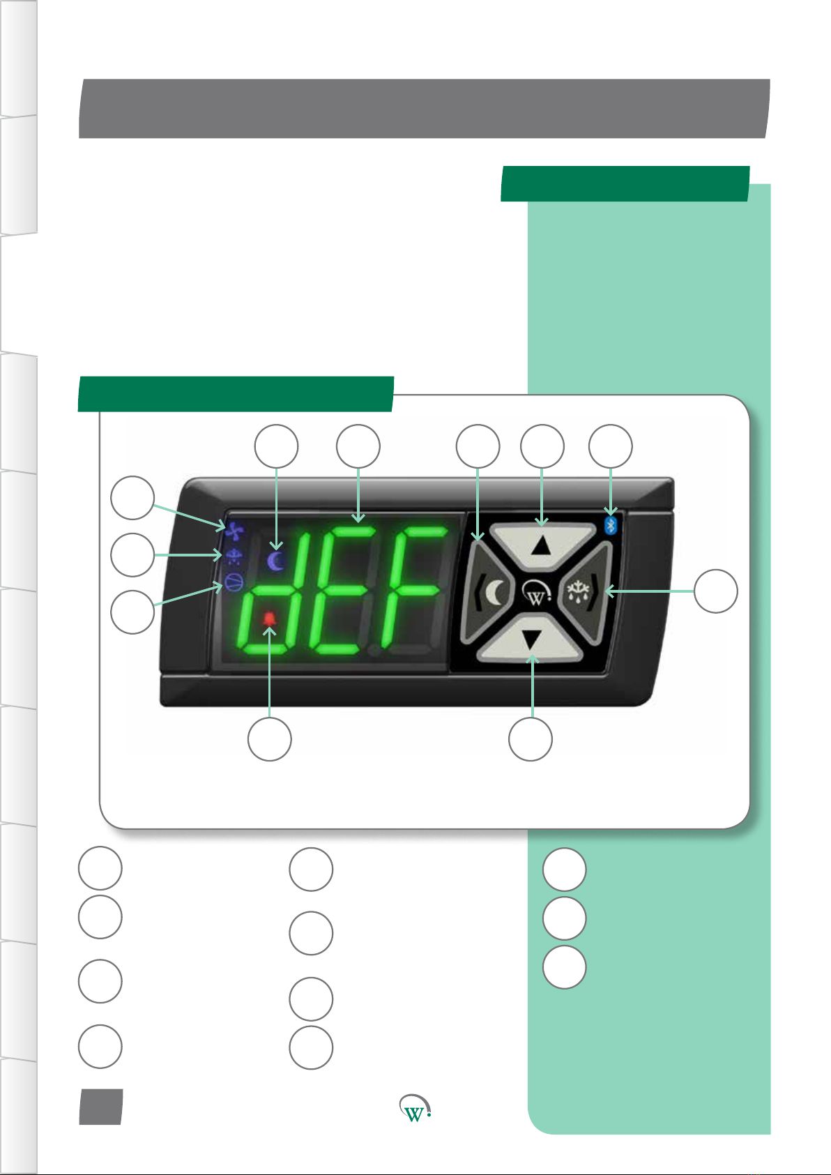
FRONT PANEL
USER INTERFACE
GRAPHICAL
USER INTERFACE PARAMETERS UPGRADING
FIRMWARE
FAULTS &
ALARMS
TECHNICAL
SPECIFICATION APPENDICES
Important Do’s and Dont’s:
Do not use water jets on the
rear of the unit. Warning!
Risk of electrocution. If
correctly installed, powerful
water jets may be applied
only to the front of the unit.
Do not drop the SCS
Connect.
There are no serviceable
parts inside the SCS
Connect. Do not open the
housing. Warning! Risk of
electrocution.
PD0006 v3.0 – 6 Dec 2017
4 4
Pleasereadthefollowingwarningstomaintainthesafefuncon
andconnuedperformanceofyourWellingtonDriveTechnologies
Limited SCS™ Connect controller:
Installaon;
InstallaonoftheSCS Connect controller other than in
accordancewiththe“Descripon&Install”seconofthis
manual will invalidate the warranty. The SCS™ Connect must
onlybeinstalledandconguredbytrainedandauthorizedsta.
Washdown;
The front of the unit may be exposed to water jets. Warning!
Therearoftheunitmustnotbeexposedtohighpressure
water jets or temporary submersion, as this will invalidate
thewarranty,andmaydamageelectroniccircuitsleadingto
prematurefailureorunsafeoperaon.Mounngoftheunit
mustbeinaccordancewithorientaonasspeciedinthe
“Descripon&Install”secon.Warning!Riskofelectrocuon.
Chemicals;
The SCS Connectcontroller’shousingismadeofpolycarbonate,
andshouldnotbeexposedtochemicalswhichaackthis
material,asthiswillinvalidatethewarrantyandmaydamage
thehousing,leadingtounsafeoperaon.Warning! Risk of
electrocuon
Temperature;
The SCS Connect controller must only be subjected to
temperaturesasspeciedinthe“TechnicalSpecicaons”
seconofthismanual.Exceedingtheseranges,eitherin
operaon,installaon,transportaon,orstorage,willinvalidate
thewarranty,andmaydamageelectroniccircuitsandhousing
components,leadingtoprematurefailure.
Vibraonandimpact;
The unit MUST be installed in such a way as to be protected
fromimpactinoperaon.Donothitordroptheunit.
Exposuretoimpacts,eitherinoperaon,installaon,
transportaon,orstorage,maydamageelectroniccircuits
andhousingcomponents,leadingtoprematurefailure,and
may cause the SCS Connect controller to become unsafe. Any
impactwhichcausesvisualdamagetothecontrollercasingwill
invalidate the warantee.
Noserviceableparts;
There are no serviceable parts inside the SCS Connect
controller.Donotopenthehousing,exceptfortherearcover,
asdescribedinthe“DescriponandInstallaon”seconof
thismanual.Openingoftheelectronicshousing,alterang
ormodifyingtheSCS Connect controller will invalidate the
warrantyandcancauseriskofelectrocuon.