manuals.online logo
Brands
  1. Home
  2. •
  3. Brands
  4. •
  5. Wenglor
  6. •
  7. Accessories
  8. •
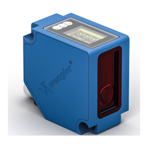
  9. Wenglor OPT2010 User manual

Wenglor OPT2010 User manual

wenglor sensoric gmbh
wenglor Straße 3
88069 Tettnang
(+49 (0)7542 5399-0
info@wenglor.com
Weitere wenglor Kontakte finden Sie unter:
For further wenglor contacts go to:
Autres contacts wenglor sous :
www.wenglor.com
DE
DE FREN
780
Änderungen vorbehalten
Right of modifications reserved
Modifications réservées
09.07.2013
1 = Sendediode/Transmitter diode/Diode émettrice
2 = Empfangsdiode/Receiver diode/ Diode réceptrice
SAP NR. 87255
High-Performance-Distanzsensor
High-performance distance sensor
Capteurs de distance hautes performances
BEDIENUNGSANLEITUNG
OPERATING INSTRUCTIONS
MODE D’EMPLOI
OPT2010
EG-Konformitätserklärung
Die Bauart der Produkte wurde in Übereinstimmung mit der Richtlinie 2004/108/EG entwickelt,
konstruiert und gefertigt. Folgende internationale Normen und Spezifikationen finden Anwendung:
•EN 60947-5-2:2007 Niederspannungsschaltgeräte,
Teil 5-2: Steuergeräte und Schaltelemente – Näherungsschalter
•EN 60825-1:2007 Sicherheit von Lasereinrichtungen
Weitere für die Anwendung gültige Normen sind zu berücksichtigen.
EC Declaration of Conformity
The products are developed, constructed and manufactured according to the directive
2004/108/EC. The following international standards and specifications apply:
•EN 60947-5-2:2007 Low-voltage switchgear and controlgear, Part 5-2: Control circuit devices
and switching elements – Proximity switches
•EN 60825-1:2007 Safety of Laser devices
Any additional standards which are applicable for the given application must be observed.
CE Déclaration de conformité
Les produits sont développés, conçus et fabriqués selon la directive 2004/108/CE.
Les normes et prescriptions appliquées sont :
•EN 60947-5-2:2007 Appareillage à basse tension, Partie 5-2 : Appareils et éléments de
commutation pour circuits de commande – Détecteurs de proximité
•EN 60825-1:2007 Sécurité des appareils à laser
D’autres normes suivant les applications sont à prendre en compte.
Anschlussbild
Connection Diagram
Schéma de raccordement
Bedienfeld
Control Panel
Panneau
+ Versorgungsspannung „+“
Supply Voltage “+”
Tension d’alimentation «+»
– Versorgungsspannung „0 V“
Supply Voltage “0 V”
Tension d’alimentation «0 V»
A Schaltausgang/Schließer (NO)
Switching output (NO)
Sortie de commutation / Fermeture (NO)
ĀSchaltausgang/Öffner (NC)
Switching output (NC)
Sortie de commutation / Ouverture (NC)
La Sendelicht abschaltbar
Emitted light can be switched off
Lumière émettrice désactivable
Bestimmungsgemäße Verwendung
Dieses wenglor Produkt ist gemäß dem folgenden Funktions-
prinzip zu verwenden:
High-Performance-Distanzsensor
Diese Sensoren ermitteln den Abstand zwischen Sensor und
Objekt nach dem Prinzip der Lichtlaufzeitmessung. Deswe-
gen haben Farbe, Form und Oberflächenbeschaffenheit des
Objekts nahezu keinen Einfluss auf den Schaltpunkt. Selbst
dunkle Objekte können vor einem hellen Hintergrund sicher
erkannt werden. Erreicht das Objekt den eingestellten Schalt-
punkt, schaltet der Ausgang. Diese Sensoren haben einen gro-
ßen Arbeitsbereich und erkennen Objekte auf große Distanzen.
Sicherheitshinweise
•Diese Anleitung ist Teil des Produkts und während der
gesamten Lebensdauer des Produkts aufzubewahren
•Bedienungsanleitung vor Gebrauch des Produkts sorgfältig
durchlesen
•Montage, Inbetriebnahme und Wartung des vorliegenden
Produkts sind ausschließlich durch fachkundiges Personal
auszuführen
•Eingriffe und Veränderungen am Produkt sind nicht zulässig
•Produkt bei Inbetriebnahme vor Verunreinigung schützen
•Kein Sicherheitsbauteil gemäß EU-Maschinenrichtlinie
Laser-/LED-Warnhinweise
LASER CLASS 1
EN60825-1
2007
Laser Klasse 1 (EN 60825-1)
Normen und Sicherheitsvorschriften
sind zu beachten.
Technische Daten
Arbeitsbereich 0…3000 mm
Einstellbereich 200…3000 mm
Versorgungsspannung 10…30 V DC
Stromaufnahme (Ub = 24 V) < 50 mA
Schaltfrequenz 1000 Hz
Ansprechzeit 0,5 ms
Spannungsabfall < 2,5 V
Max. Schaltstrom PNP 200 mA
Hysterese < 15 mm
Schaltreserve < 25 mm
Temperaturbereich −40 °C…60 °C
Temperaturdrift (−10° < Tu < 50°) < 1 %
Temperaturdrift (Tu < −10°, Tu > 50°) < 2,5 %
Kurzschlussfest ja
Überlastsicher ja
Verpolungssicher ja
Schutzklasse III
Lichtart Laserlicht (rot)
Laser Klasse 1
Schutzart IP68
Anschlussart M12×1; 4/5-polig
Ausgangsfunktion PNP-Öffner,
PNP-Schließer
Montagehinweise
Beim Betrieb der Sensoren sind die entsprechenden elektri-
schen sowie mechanischen Vorschriften, Normen und Sicher-
heitsregeln zu beachten. Der Sensor muss vor mechanischer
Einwirkung geschützt werden. Der Sensor besitzt optimale
Fremdlichteigenschaften, wenn sich der Hintergrund innerhalb
des Arbeitsbereiches befindet.
Inbetriebnahme
Achtung!
Der Schaltabstand des Sensors kann durch Drücken der
Teach-Taste eingestellt werden. Dabei ist zu beachten, dass
die Verwendung von spitzen Gegenständen, z. B. Nadeln oder
Pinzetten, die Gummimembrane über der Taste beschädigen
kann.
Einstellungen
Objekt Teachen
Durch Drücken der Teach-Taste am Sensor wird der Schaltab-
stand zum Objekt eingeteacht.
•Sensor gemäß Montagehinweis montieren
•Leuchtfleck auf das OBJEKT richten
•Teach-Taste drücken, bis die LED „Schaltzustandsanzeige“
blinkt (ca. 3 Sek.), dann loslassen
→ Schaltabstand zum Objekt wird eingestellt
•Schaltfunktion prüfen
Wird ohne Objekt geteacht, bzw. ein Objekt ist zu weit vom Sen-
sor entfernt, wird der Schaltabstand auf das Ende des Einstell-
bereichs gesetzt (Schaltzustandsanzeige blinkt schnell).
Befindet sich ein Objekt zu nah am Sensor, wird der Schalt-
abstand auf den Anfang des Einstellbereichs gesetzt.
Sendelicht abschaltbar
Der Sensor besitzt einen Eingang für Sendelicht abschalten
(PIN 5). Wird an diesem Eingang 24 V angelegt, wird das Sen-
delicht abgeschaltet.
Sensor
Teachabstand
Objekt
Schaltreserve Einschaltpunkt
Ausschaltpunkt
Hysterese
Ablaufdiagramme Verschmutzungsmeldung
nicht erkannt nicht erkannterkannt
beginnende Verschmutzung
Objekt Objekt Objekt
nicht erkannt nicht erkannterkannt
Lichtlaufzeitsensor keine Verschmutzung
Objekt Objekt Objekt
Objekt
Schaltzustandsanzeige
Verschmutzungsmeldung
Objekt
Schaltzustandsanzeige
Verschmutzungsmeldung
Objekt
Schaltzustandsanzeige
Verschmutzungsmeldung
nicht erkannt nicht erkanntnicht erkannt
fortgeschrittene Verschmutzung
Objekt Objekt Objekt
aus aus
an
aus aus
aus
aus aus
aus aus
an
aus aus
an
aus
aus aus
aus
Wartungshinweise
•Dieser wenglor Sensor ist wartungsfrei
•Eine regelmäßige Reinigung der Linse und des Displays
sowie eine Überprüfung der Steckerverbindungen werden
empfohlen
•Verwenden Sie zur Reinigung des Sensors keine Lösungs-
mittel oder Reiniger, die das Gerät beschädigen könnten
Umweltgerechte Entsorgung
Die wenglor sensoric gmbh nimmt unbrauchbare oder irrepa-
rable Produkte nicht zurück. Bei der Entsorgung der Produkte
gelten die jeweils gültigen länderspezifischen Vorschriften zur
Abfallentsorgung.
68 01 02
06
P10
01 = Schaltzustandsanzeige
= Switching Status Indicator
= Signalisation de l’état de
commutation
02 = Verschmutzungsmeldung
= Contamination Warning
= Signalisation de l’encrassement
06 = Teach-Taste
= Teach Button
= Touche apprentissage
68 = Versorgungsspannungsanzeige
= Supply Voltage Indicator
= Signalisation de la tension
d’alimentation
RoHS
FR
EN
Proper Use
This wenglor product has to be used according to the follow-
ing functional principle:
High-performance distance sensor
These Sensors measure the distance between the Sensor
and the object in accordance with the principle of transit time
measurement. For this reason, the object’s color, shape and
surface characteristics have practically no influence on the
switching point. Even dark objects can be reliably recognized
against bright backgrounds. If the object reaches the adjusted
switching point, the output switches. A large working range is
achieved by these Sensors and they recognize objects at great
distances.
Safety Precautions
•This operating instruction is part of the product and must be
kept during its entire service life.
•Read this operating instruction carefully before using the
product.
•Installation, start-up and maintenance of this product has
only to be carried out by trained personal.
•Tampering with or modifying the product is not permissible.
•Protect the product against contamination during start-up.
•Not a safety component in accordance with the EU Machin-
ery Directive.
Laser/LED Warning
LASER CLASS 1
EN60825-1
2007
Laser Class 1 (EN 60825-1)
Observe all applicable standards
and safety precautions.
Technical Data
Working Range 0…3000 mm
Adjustable Range 200…3000 mm
Supply Voltage 10…30 V DC
Current Consumption (Ub = 24 V) < 50 mA
Switching Frequency 1000 Hz
Response Time 0,5 ms
Voltage Drop < 2,5 V
max. Switching Current PNP 200 mA
Hysteresis < 15 mm
Switching Reserve < 25 mm
Temperature Range −40 °C…60 °C
Temperature Drift (−10° < Tu < 50°) < 1 %
Temperature Drift (Tu < −10°, Tu > 50°) < 2,5 %
Short Circuit Protection yes
Reverse Polarity Protection yes
Overload Protection yes
Protection Class III
Light Source Laser (red)
Laser Class 1
Protection IP68
Connection M12×1; 4/5-pin
Output Function PNP NC, PNP NO
Mounting instructions
During operation of the Sensors, the corresponding electrical
and mechanical regulations, as well as safety regulations must
be observed. The Sensor must be protected from mechanical
impact. The Sensor has optimal ambient light characteristics if
the background changes within the Working Range.
Initial Operation
Attention!
The sensing distance can be set by pressing the Teach-In key.
However, if a sharp object is used to this end, for example a
needle or tweezers, damage to the rubber membrane which
covers the key may result.
Adjusting instructions
Object Teach-In
By pressing the Teach-In key at the Sensor the switching dis-
tance to the object is taught-in.
•Mount the Sensor according to the mounting instructions.
•Adjust the light spot to the object.
•Press Teach-In key until the LED “Switching Status
Indicator” blinks (approx. 3 sec.) then release.
→Switching Distance to object is set.
• Check the switching function.
If you teach without an object or the object is located too far
away from the Sensor, the Switching Distance is set to the end
of the Working Range. (“Switching Status Indicator” blinks
fast).
If the object is located too close to the Sensor, the Switching
Distance is set to the beginning of the Working Range.
Emitted light can be switched off
The Sensor has an Input to switch off the emitted light (PIN 5).
If 24 V is applied to this Input, the emitted light is switched off.
Sensor
Teach Distance
Object
Switching Reserve
Making point
Breaking point
Hysteresis
Diagram Contamination warning
Object Object Object
Transmit Time Sensor no contamination
Object Object Object
Object
Switching Status
Contamination Warning
Object
Switching Status
Contamination Warning
Object
Switching Status
Contamination Warning
Object Object Object
off off
on
off off
off
off off
off off
on
off off
on
off
off off
off
not detected not detectednot detected
not detected not detecteddetected
beginning contamination
advanced contamination
Maintenance Instructions
•This wenglor Sensor is maintenance-free.
•It is advisable to clean the lens and the display, and to
check the plug connections at regular intervals.
•Do not clean with solvents or cleansers which could
damage the device.
Proper Disposal
wenglor sensoric gmbh does not accept the return of unus-
able or irreparable products. Respectively valid national waste
disposal regulations apply to product disposal.
Notice d’utilisation
Ce produit wenglor doit être utilisé selon le mode de fonction-
nement suivant :
Capteurs de distance hautes performances
Ces capteurs déterminent la distance entre le capteur et
l’objet. Ils travaillent avec le principe de mesure du temps
de transit de la lumière. C’est pourquoi la couleur, la forme
et l’état de surface des objets n’ont pratiquement aucune
influence sur les résultats de la mesure. Même les objets
foncés devant un arrière-plan clair peuvent être détectés avec
certitude. Si l’objet atteint la portée réglée, la sortie commute.
Ces capteurs ont de larges plages de mesure et détectent
des objets à de grandes distances.
Consignes de sécurité
•Cette notice d’utilisation fait partie intégrante du produit et
doit être conservée durant toute la durée de vie du produit.
•Lisez la notice d’utilisation avant la mise sous tension.
•L’installation, les raccordements et les réglages doivent être
effectués uniquement par du personnel qualifié.
•Toute intervention ou modification sur le produit est pros-
crite.
•Lors de la mise en service, veillez à protéger l’appareil
d’éventuelles salissures.
•Aucun composant de sécurité selon la directive
« Machines » de l’Union Européenne.
Laser/LED Mise en garde
LASER CLASS 1
EN60825-1
2007
Appareil à laser de classe 1
(EN 60825-1)
Respecter les normes et
prescriptions de sécurité
Données techniques
Plage de travail 0…3000 mm
Plage ajustable 200…3000 mm
Tension d’alimentation 10…30 V DC
Consommation (Ub = 24 V) < 50 mA
Chute de tension < 2,5 V
Courant commuté max. PNP 200 mA
Hystérèsis < 15 mm
Réserve de commutation < 25 mm
Dérive en température (−10° < Tu < 50°) < 1 %
Dérive en température (Tu < −10°, Tu > 50°) < 2,5 %
Protection contre les court-circuit oui
Protection contre les surcharges oui
Protection contre les inversions de polarité oui
Classe de protection III
Température d’utilisation −40 °C…60 °C
Type de lumière Laser (rouge)
Degré de protection IP68
Classe Laser 1
Fréquence de commutation 1000 Hz
Temps de réponse 0,5 ms
Instructions de montage
Pour le bon fonctionnement du capteur, il est important de
respecter les normes électriques et mécaniques et d’observer
les règles de sécurité. Le capteur doit être protégé contre les
chocs mécaniques. Le capteur possède des caractéristiques
optimales de lumière ambiante si l’arrière-plan change dans
la zone de travail.
Mise en service
Attention!
La portée du détecteur peut être réglée en appuyant la touche
apprentissage. Eviter l’utilisation d’objets pointus pour cette
manipulation. La membrane en caoutchouc peut s’abîmer.
Réglages
Apprentissage sur objet
L’apprentissage de la distance de détection sur l’objet se
réalise en appuyant sur le bouton Teach du capteur.
•Installer le capteur suivant les instructions de montage.
•Diriger le spot lumineux sur l’objet.
•Appuyer sur le bouton Teach jusqu’à ce que la LED
indiquant l’état de commutation clignote (environ 3 s),
puis relacher.
→La distance de commutation à l’objet a été réglée.
•Vérifier la commutation.
Si un apprentissage est réalisé sans objet, par exemple un
objet trop éloigné, alors la distance de commutation sera la
distance maximale de travail du capteur (la LED de commuta-
tion clignote rapidement).
Si un apprentissage est réalisé sur un objet trop proche, alors
la distance de commutation sera la distance minimale de
travail du capteur.
Lumière émettrice désactivable
Le capteur a une entrée pour désactiver la lumière émettrice
(PIN 5). Une tension de 24 V sur cette entrée désactive la
lumière émettrice.
Capteur
Teach Distance
Objet
Réserve de commutation
Point d’enclenchement
Point de désactivation
Hystérèse
Diagramme Signalisation d’encrassement
Objet Objet Objet
Capteur temps transit pas d’encrassement
Objet Objet Objet
Objet Objet Objet
début d’encrassement
encrassement avancé
Objet
Signalisation de l’état de
commutation
Signalisation de
l’encrassement
Objet
Signalisation de l’état de
commutation
Signalisation de
l’encrassement
Objet
Signalisation de l’état de
commutation
Signalisation de
l’encrassement
non detécté non detéctédetécté
allumée
allumée
allumée
éteint éteint
éteint éteint éteint
éteint éteint
éteint éteint
éteint éteint
éteint éteint
éteint
éteint
non detécté non detécté
non detécté non detécté non detécté
detécté
Instructions de maintenance
•Ce capteur wenglor ne nécessite pas d’entretien particulier.
•Il est recommandé de nettoyer régulièrement la lentille et
le boîtier ainsi que de vérifier régulièrement les câbles de
connexion.
•Ne pas laver avec des solvants ou autres produits
nettoyants qui pourraient endommager l’appareil.
Mise au rebut
La société wenglor sensoric gmbh ne reprend ni les produits
inutilisables ni les produits irréparables. Veuillez respecter la
réglementation en vigueur en mettant le produit au rebut dans
un endroit prévu à cet effet par les autorités publiques.
Other Wenglor Accessories manuals

Wenglor ShapeDrive G4 MLAS 1 Series User manual

Wenglor

Wenglor ShapeDrive G4 MLAS 1 Series User manual

Wenglor ODX202 User manual

Wenglor

Wenglor ODX202 User manual

Wenglor P1XF001 User manual

Wenglor

Wenglor P1XF001 User manual

Wenglor IQ Series User manual

Wenglor

Wenglor IQ Series User manual

Wenglor CP25QXVT80 User manual

Wenglor

Wenglor CP25QXVT80 User manual

Wenglor OPT2001 User manual

Wenglor

Wenglor OPT2001 User manual

Wenglor P1NK208 User manual

Wenglor

Wenglor P1NK208 User manual

Wenglor P2KK004 User manual

Wenglor

Wenglor P2KK004 User manual

Wenglor OPT2203 User manual

Wenglor

Wenglor OPT2203 User manual

Wenglor P1NE Series User manual

Wenglor

Wenglor P1NE Series User manual

Wenglor P1KL Series User manual

Wenglor

Wenglor P1KL Series User manual

Wenglor UMF402U035 User manual

Wenglor

Wenglor UMF402U035 User manual

Wenglor GM 04 User manual

Wenglor

Wenglor GM 04 User manual

Wenglor OCP801P0150P User manual

Wenglor

Wenglor OCP801P0150P User manual

Wenglor OPT2011 User manual

Wenglor

Wenglor OPT2011 User manual

Wenglor PNBC1 Series User manual

Wenglor

Wenglor PNBC1 Series User manual

Wenglor P1PA00 Series User manual

Wenglor

Wenglor P1PA00 Series User manual

Wenglor OPT2130 User manual

Wenglor

Wenglor OPT2130 User manual

Wenglor YR24PCT2 User manual

Wenglor

Wenglor YR24PCT2 User manual

Wenglor P1KK Series User manual

Wenglor

Wenglor P1KK Series User manual

Wenglor OPT2168 User manual

Wenglor

Wenglor OPT2168 User manual

Wenglor OPT2015 User manual

Wenglor

Wenglor OPT2015 User manual

Wenglor P2KH002 User manual

Wenglor

Wenglor P2KH002 User manual

Wenglor X1TA101MHT88 User manual

Wenglor

Wenglor X1TA101MHT88 User manual

Popular Accessories manuals by other brands

Quincy lab 140AE-1 operating manual

Quincy lab

Quincy lab 140AE-1 operating manual

HomePro ZIR000 user manual

HomePro

HomePro ZIR000 user manual

DOL 20SCR Technical user guide

DOL

DOL 20SCR Technical user guide

RAB Smart Task installation manual

RAB

RAB Smart Task installation manual

Kemppi KMS 300 quick guide

Kemppi

Kemppi KMS 300 quick guide

Stearns 57,500 Series Installation and service instructions

Stearns

Stearns 57,500 Series Installation and service instructions

iGuzzini TWILIGHT COPENAGHEN manual

iGuzzini

iGuzzini TWILIGHT COPENAGHEN manual

Adelaide Annexe & Canvas Avan Deluxe installation guide

Adelaide Annexe & Canvas

Adelaide Annexe & Canvas Avan Deluxe installation guide

OHAUS 5000 instruction manual

OHAUS

OHAUS 5000 instruction manual

HOME8 WLS1300 quick start guide

HOME8

HOME8 WLS1300 quick start guide

MAXBOTIX MaxSonar quick start guide

MAXBOTIX

MAXBOTIX MaxSonar quick start guide

ioSmart iSmart56 Installation and user guide

ioSmart

ioSmart iSmart56 Installation and user guide

Focusrite Scarlett 18i8 user guide

Focusrite

Focusrite Scarlett 18i8 user guide

Velleman ED38105 user manual

Velleman

Velleman ED38105 user manual

JumpSport SkyBounce user manual

JumpSport

JumpSport SkyBounce user manual

Prima-Temp PRIYA Instructions for use

Prima-Temp

Prima-Temp PRIYA Instructions for use

Tefcold BC85I-BC85I W user manual

Tefcold

Tefcold BC85I-BC85I W user manual

Vaisala WMS302 user guide

Vaisala

Vaisala WMS302 user guide

manuals.online logo
manuals.online logoBrands
  • About & Mission
  • Contact us
  • Privacy Policy
  • Terms and Conditions

Copyright 2025 Manuals.Online. All Rights Reserved.