Westell AISG-RM3 User manual
Equipment Issue B
030‐101806 Rev. A, October 2013
Section AIS‐RM3‐20B
R
1310IBRA
ECopyright 2013 EWestell, Inc. All rights reserved. Printed in the United States of America.
Westellris a trademark of Westell, Inc. Page 1 of 22
WestellrAISG‐RM3 Rack‐Mount, 3‐Port, AISG Controller
CONTENTS PAGE #
1. GENERAL 1....................................
2. FEATURES & OPTIONS 2.......................
3. GETTING STARTED 4..........................
4. CONFIGURING THE AISG‐RM3 6...............
5. USING THE AISG‐RM3 9........................
6. MANAGING ANTENNA CONFIGURATIONS 9.....
7. USING THE CONSOLE INTERFACE 17...........
8. PERFORMING FIRMWARE UPGRADES 17.......
9. ERROR & ALARM CODES/MESSAGES 19........
10. CUSTOMER & TECHNICAL SERVICESRES 19...
11. WARRANTY & REPAIRS 21......................
12. SPECIFICATIONS 21...........................
13. ACRONYMS & ABBREVIATIONS 21..............
1. GENERAL
1.1 Document Purpose
This document provides general information, hardware and
software feature descriptions, installation information, as well
as configuration and management information for the Westell
AISG‐RM3 Rack Mountable 3‐Port AISG Controller, a con
troller for AISG Antenna Line Devices (ALD). The AISG‐RM3
is shown in Figure 1, and comes with both rack‐mount and
wall‐mount ears. See Table 19 for ordering information.
1.2 Document Status
Whenever this practice is updated, the reason will be stated here.
This document reflects the Issue B equipment which accepts an
input power supply range of ‐48VDC to +24VDC, and uses con
tact relays as alarm outputs.
Figure 1. AISG‐RM3 AISG Controller
‐ NOTE ‐
Hereafter, the AISG‐RM3 may be referred to as the “controller”
or as the “AISG‐RM3.”
1.3 Product Purpose and Description
Westell's AISG‐RM3 Rack Mountable 3‐Port AISG Control
ler is used to control, manage, adjust, monitor, and power a
group of AISG devices such as TMAs and RET antennas. Local
and remote control and management of the devices is provided
via the on‐board Ethernet port and a web interface.
‐ LATEST DOCUMENTATION NOTE ‐
Visit www.westell.com for the latest version of this document and
for other product documentation.
1.4 Product Mounting
The AISG‐RM3 can be rack or wall mounted using the provided
mounting ears. It may also be set on a desk or tabletop.
1.5 System Application
The AISGRM3 communicates with Westell's TMA using
AISG protocol. The AISG signals are injected onto and pulled
from the center PIN of the RF feeder cable running to the TMA
using a Current Injector Modem (CIM).
1.6 Product Default Parameters
Please note the default parameters for the controller below:
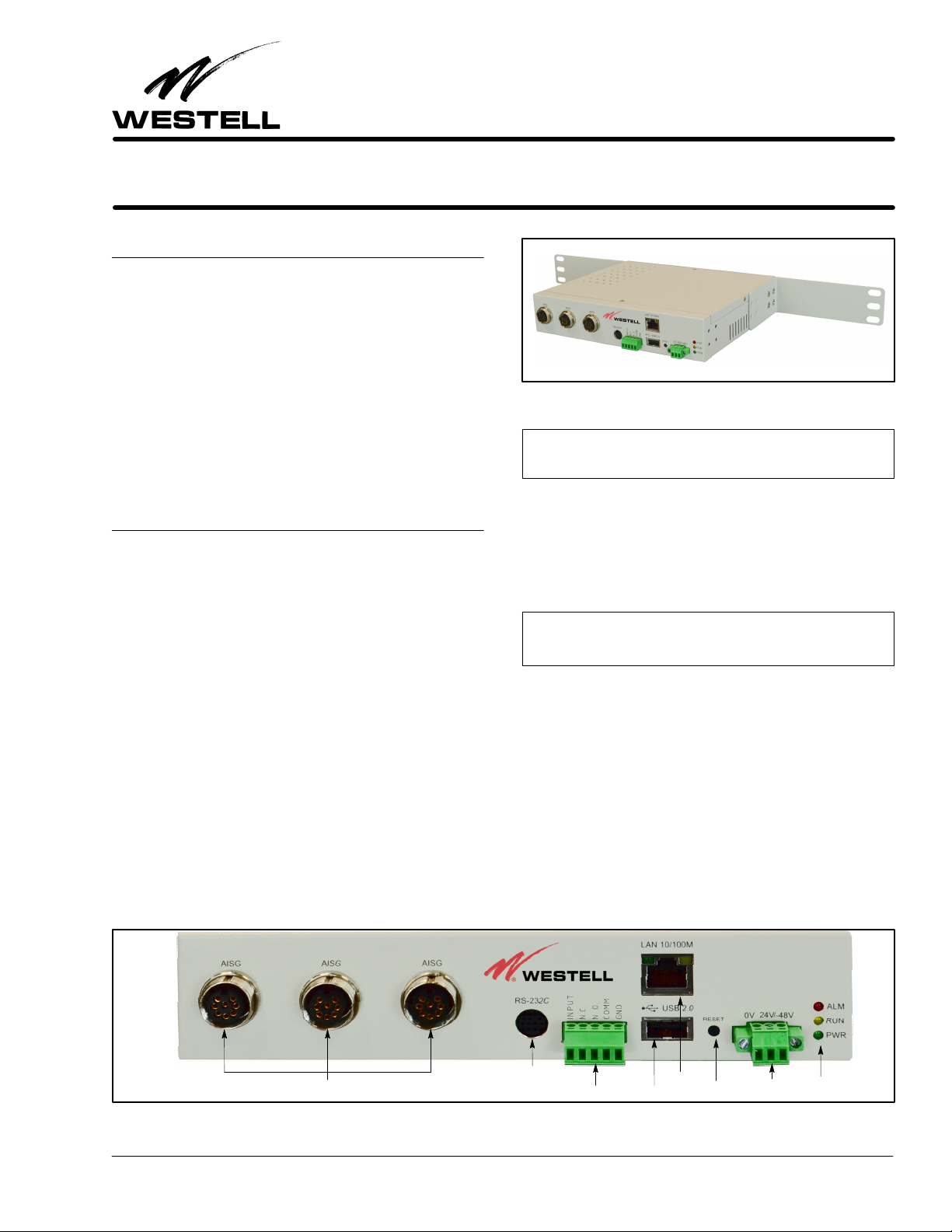
Figure 2. Front View of AISG‐RM3 Controller
RS‐232 Port
Alarm Contacts
3 AISG Ports (Female) Power Jack LEDs
Reset ButtonUSB Port
Ethernet
Section AIS‐RM3‐20B 030‐101806 Rev. A R
1310IBRA
2
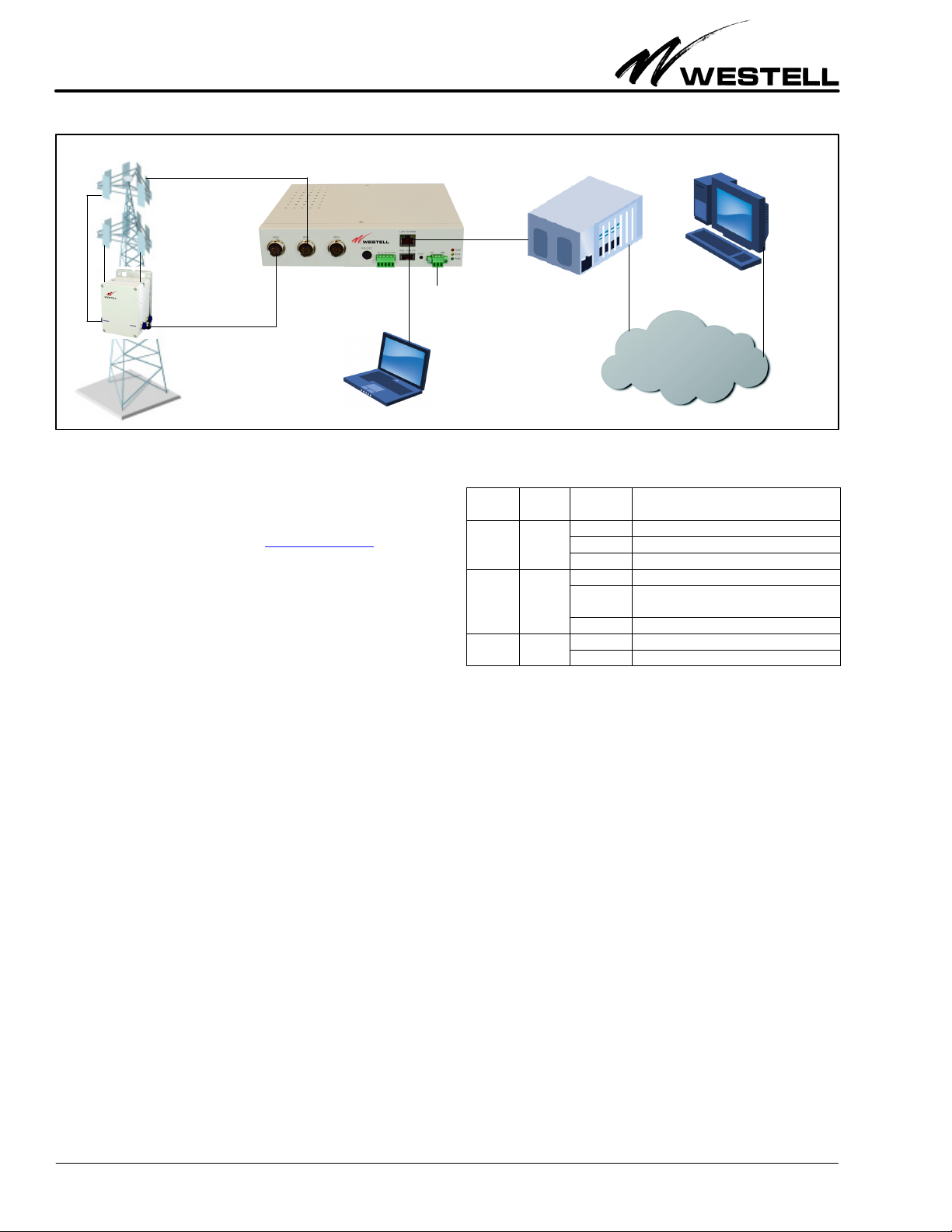
Figure 3. AISG‐RM3 Controller Sample Application
IP Network
Base Station
Off−site
control
Laptop
(on−site
control)
AISG-RM3 Controller
RET Antenna
TMA Power
Input
Default IP Address: 192.168.0.30
Default User Name: admin Default Password: admin
Latest documentation location: http://westell.com
2. FEATURES & OPTIONS
The features and highlights of the Westell AISG‐RM3 are lis
ted below. See the paragraphs that follow in this section for
additional information on some of the features.
2.1 Highlights and Benefits
The controller provides the following benefits.
SSupports both AISG v1.1 and AISG v2.0 for remote control
and monitoring of AISG line devices
SRemote setting of TMA gain and mode
SRemote adjustment of RET antenna tilt angle
SRET antenna configuration and calibration
SManagement of base station site information such as site
ID, name, location and contact
SManagement of user accounts with multiple security levels
SPower saving mode to suspend the power output of AISG port
2.2 Front Panel Features
On the front panel of the controller are eight ports (including
3 AISG ports to connect to AISG line devices), a reset button,
a n d t h r e e LE D s , a s sh o w n i n Ta b l e 1 a n d Ta b l e 4 b e l o w an d ex
plained in the paragraphs that follow.
LED Color State/
Status Description
ALM
(alarm) Red
Steady AISG RM3 cannot ping default gateway
Flashing Alarm present.
Off No alarm present
RUN Yellow
Steady AISG RM3 busy
Flashing Indicates system is running or ready for
use.
Off
PWR
(power) Green Steady On steady when power is present.
Off Unit not powered.
Table 1. LED Conditions and States
2.2.1 LEDs
Three LEDs are located on the front panel of the AISG‐RM3.
Their states and functions are explained in Table 1.
2.2.2 AISG Ports
Three standard, female, 8‐pin, AISG ports are provided on the
front of the controller. Each AISG port can control up to 8 an
tenna line devices by using daisy‐chained cables.
2.2.3 RS‐232 Port
The round RS‐232 port on the controller is used to access the
console or command line interface. See Figure 4 for the
pin‐outs of the DB‐9 RS‐232 connector and for an illustration
of the pin locations. See Part 7 for more information on this in
terface.
2.2.4 Alarm Connector
A pluggable alarm connector is provided for connection with
external alarm reporting equipment. The alarm output is a con
tact relay. Five port holes for stripped wires are provided on the
connector, with screws that accept a small slotted screwdriver
for tightening and securing the alarm wires which are inserted

Section AIS‐RM3‐20B
030‐101806 Rev. A
R
1310IBRA 3
Figure 4. RS‐232 Cable's Connector Pin‐out
Pin 1: Data Carrier Detect Pin 6: Data Set Ready
Pin 2: Receive Data Pin 7: Request to Send
Pin 3: Transmit Data Pin 8: Clear to Send
Pin 4: Data Terminal Ready Pin 9: Ring Indicator
Pin 5: Signal Ground
Mates with
connector on
AISG‐RM3
controller
front panel
Mates with
connector on
computer
RS232 Female pin‐out to Mini Din Male pin‐out
into the port holes (16 ga. max.) This connector is labelled “IN
PUT N.C. N.O. COMM GND”.
INPUT = Digital Input
N.C. = Normally Closed
N.O. = Normally Open
COMM = Communication
GND = Ground
2.2.4.1 Digital Input Contacts
The digital input channel is used to interface a potential free
contact, e.g., a relay. It could be a fire alarm sensor, door sensor,
or failure signal from a power supply in a base station site. The
DI can read the digital input channel status and determine its
alarm state. The INPUT and GND pins are used to make a digit
al input connection.
Pin Label Description Specification
INPUT Digital Input Channel Logical level 0/1.
Max. Input DC +30V, 100mA
GND Ground of I/O Channels Ground
Table 2. Digital Input Contacts
The DI alarm settings are configured in the System Setting
menu.
2.2.4.2 Digital Output Contacts
This module has two relay outputs. The relay outputs are dedic
ated circuits that can be directly connected inline with the
desired control or indicating device.
Connector Label Pin Description Specification
INPUT Digital Input channel
Logical level 0/1.
Max. input DC
+30V, 100mA
N.C. Normally Closed relay output Contact Capacity:
AC 125V / 0.5A
DC 24V / 1A
N.O. Normally Open relay output
COMM Common N/A
GND Ground of I/O channels Ground
Table 3. Alarm Connector Pin‐outs
2.2.5 Ethernet Port
An Ethernet port labelled “LAN 10/100M” is provided on the
front of the controller. This port is used to provide access to the
web‐based user interface either by connecting directly to a local
PC or to a router for remote access.
2.2.6 USB Port
A USB port labelled “USB 2.0” on the front of the controller
is reserved for future expansion.
Port Label Type Description
AISG 8‐pin
female
3 AISG ports provided, each Standard
AISG 8pin female IEC 601309 bias/
RS485, connects to an antenna line
device (RET or TMA). Each can control up
to 8 daisy‐chained antenna line devices.
RS‐232
9‐pin,
round,
female
1 RS‐232 port, used to connect to serial
port of a PC for console access
INPUT
N.C.
N.O.
COMM
GND
5‐pin
pluggable
Alarm Connector, 5 wire port holes, screw
down type, accepts 16 gauge wire (max.)
LAN 10/100M RJ45 Used to connect to a PC or a network
USB 2.0 USB 2.0,
female Not used, reserved for future use.
24V ‐48V 3‐pin
pluggable
Power connector, 3 wire port holes,
screw down type, accepts 16 gauge wire
(max.), used to connect to power source
Table 4. Front Panel Ports and Connectors
2.2.7 Reset Button
A recessed reset button is provided on the front of the control
ler to perform a hard power‐on reset. Press the button
momentarily to restart the AISG‐RM3 controller. Press and
hold the button for approximately 6 seconds to restore network
settings to the factory default.
2.2.8 Power Connector
A 3‐port pluggable power connector is provided on the front of
the controller to power the unit. The input voltage range for the

Section AIS‐RM3‐20B 030‐101806 Rev. A R
1310IBRA
4
AISG‐RM3 is ‐48VDC to 24VDC, and the unit is polarity in
sensitive.
3. GETTING STARTED
Installation consists of unpacking the equipment to verify all
equipment ordered was received, inspecting the equipment for
damages, following proper safety precautions, gathering tools
and materials that will be needed, mounting or installing the
AISG‐RM3, connecting all cables to the AISG‐RM3, and set
ting up computer communication with the AISG‐RM3. The
following paragraphs provide detailed instructions for perform
ing these procedures.
‐ INSPECTION NOTE ‐
If not previously inspected at the time of delivery, visually inspect
the unit for damages prior to installation. If the equipment has
been damaged in transit, immediately report the extent of the
damage to the transportation company and to Westell (see Part
10 for telephone number).
CAUTION ‐ STATIC‐SENSITIVE
This product contains static‐sensitive components! Proper
electrostatic discharge procedures must be followed to
maintain personal and equipment safety. Do not store units
near magnetic, electromagnetic or electrostatic fields. Always
store or ship units in the original static‐protective packaging
from Westell. Use anti‐static mats when working on units.
‐ PRECAUTIONARY STATEMENT ‐
‐ This equipment is intended to be used behind devices that
provide primary lightning protection.
‐ This installation should conform to Local Codes and NEC
requirements.
‐ This equipment is to be installed in a restricted access location.
CAUTION
Risk of electric shock. Differential voltages of up to 60V can exist
on the bias or telecommunications lines.
‐ CAUTION ‐
Never apply power until all installer connections are made.
‐ GROUNDING NOTE ‐
Always follow the National Electrical Code (NEC) rules, local safety pre
cautions, and standard operating procedures for grounding the equipment
when installing, upgrading, repairing or maintaining equipment. Any in
structions or information contained herein is subordinate to local codes,
operating procedures or practices.
‐ CAUTION ‐
Improper grounding could be service affecting and cause
service interruptions.
‐ CAUTION ‐
Use care when connecting cables and wires, do not force a cable
or wire into place. If a cable or wire resists insertion, remove it
and check for obstructions in or near the connector's slots and
port holes.
3.1 Gathering Tools and Supplies
The following tools and supplies may be needed to physically
install the AISG‐RM3 controller.
Tools/Materials Needed to Physically Install the Controller
-Standard installation tools, including: wrenches, screw
drivers, power drill and bits, wall mount screws, cable ties,
as needed
-Alarm and power cables/wires of sufficient length to extend
from the AISG‐RM3 to the power source and alarm device
(two 22' cables included)
-AISG cables of sufficient length to extend from the
AISG‐RM3 to the antenna line device (three 22' Y‐cables
included)
-Wire strippers and wire cutters
-Any needed cable management equipment/materials
3.2 System/Computer Connection Requirements
To connect and network the controller with a computer, the fol
lowing items/requirements are needed:
1. Internet Explorer 6.0 or other web browser
2. Screen resolution of 1024 x 768, or greater
3. A user name and password (see Paragraph 3.6)
3.3 Mounting the AISG‐RM3 Controller
Each Westell AISG‐RM3 comes with mounting brackets for
rack or wall mounting. The longer brackets are used to mount
the unit in an equipment rack (rack‐mount screws included).
The two short brackets are used to mount the unit on a wall.
Use appropriate wall‐mount screws per the wall type and com
pany practices.
3.4 Connecting Cables to AISG‐RM3
Follow the steps below to make all cable connections to the
AISG‐RM3.
1. Connect the Ethernet port on the controller to a local PC
using a standard Ethernet cable.
2. For use with Westell TMA's, connect one of the AISG fe
male ports on the controller to a Current Injector Modem
using one of the supplied AISG Ycables.
3. Repeat the step above for all antenna line devices (RET or
TMA).
Section AIS‐RM3‐20B
030‐101806 Rev. A
R
1310IBRA 5
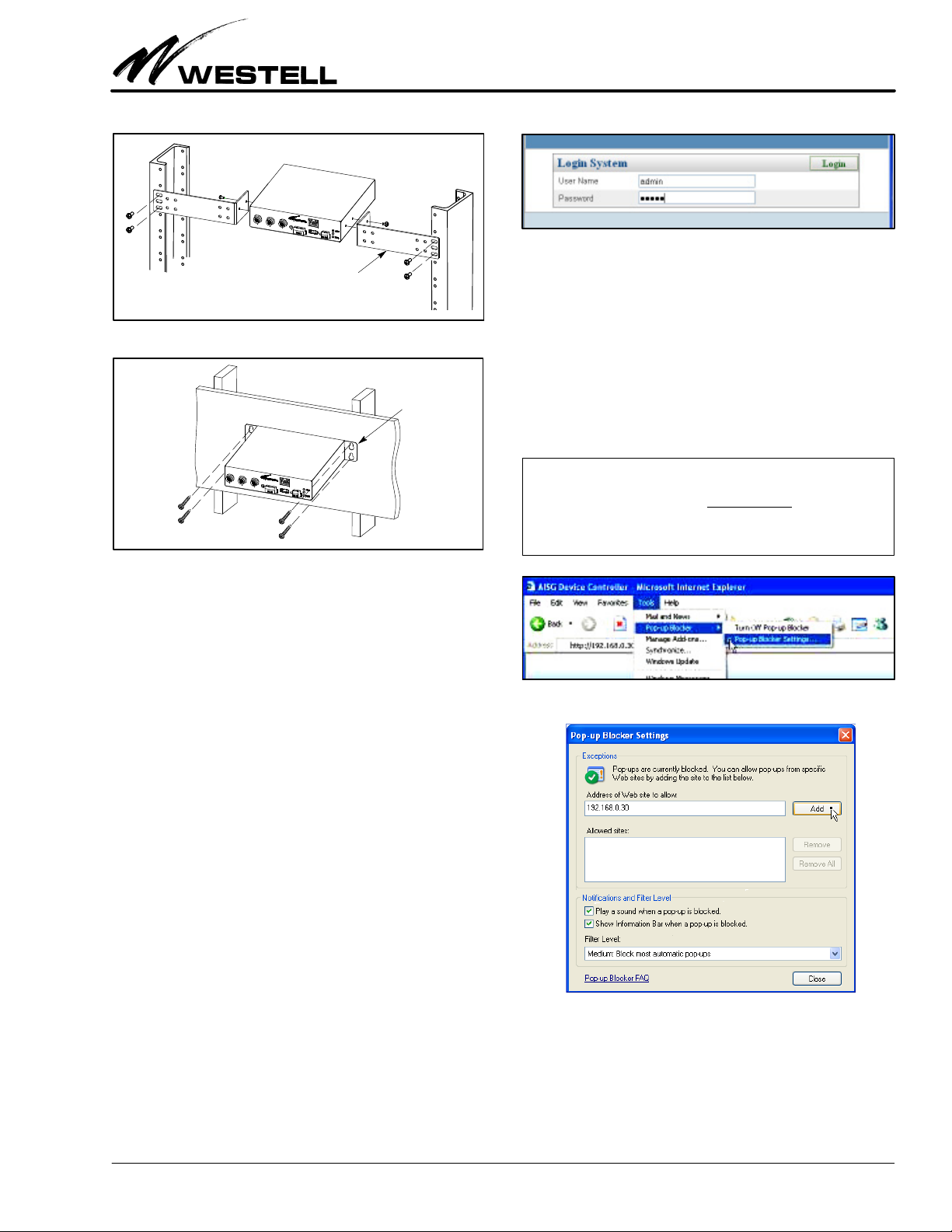
Figure 5. Rack Mounting
AISG‐RM3
Figure 6. Wall Mounting
Long L‐brackets for rack mounting
Short flat brackets
for wall mounting
4. Connect DC power to the power port on the controller. The
power LED indicator should light up and the controller
should start to boot. Wait for the RUN LED to blink which
indicates that the controller is ready for use.
5. For optional console access, connect the RS232 port on the
controller to the PC using a DB‐9 to mini‐DIN conversion
cable (not provided, shown in Figure 4).
3.5 Setting the IP Address / Networking
The AISG‐RM3 controller has been factory preset with an IP
address of 192.168.0.30. In order to access the AISG‐RM3 con
troller from a PC connected directly by an Ethernet cable, the
PC’s IP address must belong to the same network.
3.6 Accessing / Logging In to the Controller
To access the AISG‐RM3 controller, you need to first log in.
1. Address the controller. From your PC, launch Internet Ex
plorer and type the IP address of the AISG‐RM3 controller
in the Address Bar.
http://<IP address of AISG‐RM3>
The default IP address of the controller has been preset to
192.168.0.30. Enter this IP address for first‐time access. It
can be changed later. The browser should display the Login
page as shown in Figure 7.
Figure 7. Login Screen
2. Login to the controller. At the Login System screen, enter
the user name and password:
User Name = admin
Password = admin
These are default values. This user account is the default
system administrator account which has full access permis
sions. You should change the password of the default
administrator account after you first log in. You should cre
ate other accounts for doing general operations.
‐ BROWSER POP‐UP BLOCKING WARNING‐
The webbased interface makes use of popup windows to display
messages. If your browser has the popup blocking feature turned on,
then you may not see all of the messages. You may either: A) turn off
the blocking of popups, or B) configure the blocking to allow popups
that originate from the Westell AISG‐RM3 controller’s IP.
Figure 8. Locating the Pop‐up Blocker Tool
Figure 9. Configuring Pop‐up Blocker Tool
3. Skip to Part 4 or Log out. Skip to Part 4 if configuration is
desired at this time. If configuration and management will
take place at a later time, log out of the system. Click on the
Logout tab near the top right of the screen (see Figure 10)
to log out from the controller.

Section AIS‐RM3‐20B 030‐101806 Rev. A R
1310IBRA
6
Figure 10. Logging Out
See Part 7 for information on console access.
4. CONFIGURING THE AISG‐RM3
In this section, configuring the system settings and managing
user accounts are explained. If not already logged in, log in to
the system as explained in Paragraph 3.6. After you log in, the
main menu screen (Figure 11) is displayed.
Figure 11. Main Menu Screen
Menu tabs in top row
Current user name
In the upper right corner, the current user name is displayed. It
is “admin” in this case (see red arrow). Menu names are dis
played as “tabs” in the first row near the top of the main menu.
The available menus are:
_Device Status _System Account
_Antenna Config File _Summary Report
_Site Information _Logout
_System Setting
4.1 Configure the System Settings
Click on the System Setting tab (as shown in Figure 11) to open
the System Setting menu. The System Setting menu (Figure 12)
which appears is further divided into five sections or panels:
ÆNetwork Setting (see Paragraph 4.1.1)
ÆSystem Information (see Paragraph 4.1.2)
ÆPower Setting (see Paragraph 4.1.3)
ÆDevice Setting, (see Paragraph 4.1.4) and
ÆSystem Time Setting (see Paragraph 4.1.5)
4.1.1 Network Settings
The Network Setting section is where the values for IP address,
SubNetwork Mask, and Gateway IP can be changed. Obtain the
new IP for the AISG‐RM3 controller from the site network ad
ministrator. In this example, the settings are:
AISG‐RM3 IP: 192.168.0.92
Gateway IP: 192.168.0.1
Figure 13. Network Settings
The data fields are explained in Table 5.
Figure 12. System Setting Screen
Æ
Æ
Æ
Æ
Æ

Section AIS‐RM3‐20B
030‐101806 Rev. A
R
1310IBRA 7
Field Name Description / Options
IP Address Change to the new IP address assigned to the AISG‐RM3
controller at the site network.
SubNetwork
Mask
Change to the new SubNetwork Mask used at the site net
work.
Gateway IP Change to the new Gateway IP used at the site network.
Table 5. Network Settings / IP Address Fields
Click on the Save button in the upper right corner once you have
finished changing the values. An alert window appears.
Click on the OK button to confirm the save.
After saving, the new settings will only take effect after the sys
tem is rebooted. Click the Reboot button to reboot the system.
Click OK to confirm and initiate the reboot process.
Wait for the process to end. You may need to reconnect to the
AISG‐RM3 using the new IP if the IP is changed.
4.1.2 System Information and Language
The System Information section (see Figure 12 or Figure 14)
shows the Product Model, Serial No., Hardware Version and
Software Version of the AISG‐RM3 system. The desired user in
terface language can also be changed here. Select the preferred
language from the dropdown list and click the Set button to ap
ply the change.
Figure 14. System Information Area
4.1.3 Power Setting
In the Power Setting section (Figure 15), the power voltage and
power supply mode provided to the connected AISG devices can
be changed. Change the settings per company practice, refer
ring to Table 6 as needed, then click on the Set button to apply
the changes.
Figure 15. Power Setting Area
Field Name Description / Options
Power Supply DC 12V or DC 24V. Check to select the proper voltage.
Power Mode:
Always On
Check to supply power continuously.
Power Mode:
Power Save
This is a power saving mode. Check to supply power only
when a command is initiated; otherwise power is not sup
plied.
Table 6. Power Setting Fields
When the Set Power process is completed, the following popup
window is displayed. Click on the Close button to close it.
4.1.4 Device Setting
In the Device Setting section, select the Scan Length value used
when scanning for devices. The default value is 4. This value can
be increased if a connected device is not being distinguished
from another during a scan.
Figure 16. Device Setting Area - Scan Length
Click on the Set button to apply the changes. Click on the Close
button when the process is finished.
4.1.5 System Time Setting
The System Time Setting section is used to set the system date
and time. The date uses the mm/dd/yyyy format. By clicking on
the Select Date button, a calendar popup appears which can be
used to select the date. The time setting uses the 24hour format.
Figure 17. System Time Setting Area - Date Format
Click on the Set button to apply the changes. Click on the Close
button when the process is done.
Section AIS‐RM3‐20B 030‐101806 Rev. A R
1310IBRA
8
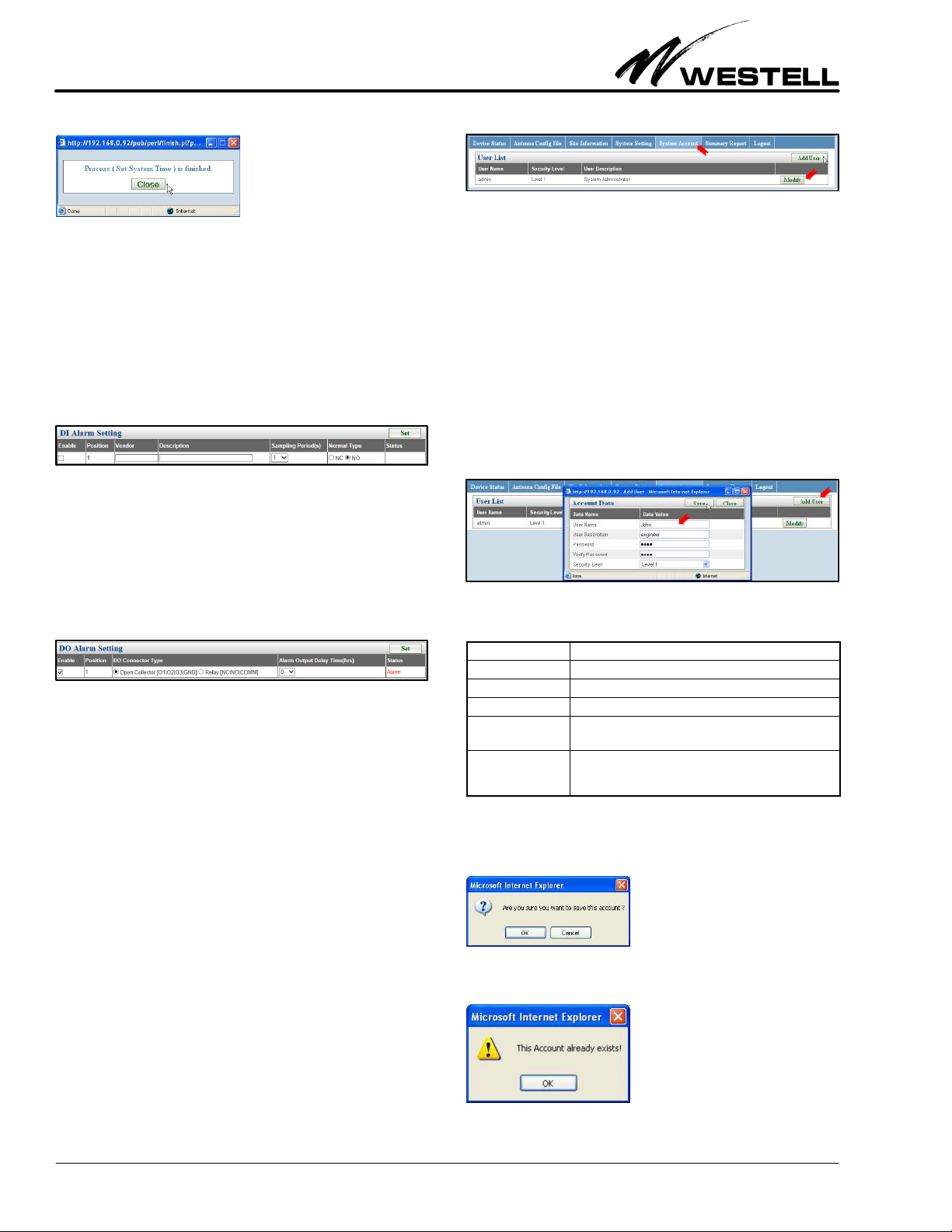
4.1.6 DI Alarm Settings
The DI Alarm Settings are used to configure the digital input
contacts (INPUT and GND alarm contacts). You may enable/
disable and define its sampling period. When enabled, the Status
field indicates the current condition of the INPUT contact. It
will indicate Normal or Alarm. These conditions do not trigger
any other events, they are simply displayed in the Status field.
Figure 18. DI Alarm Settings
4.1.7 DO Alarm Settings
The DO Alarm Settings are used to configure contact relay
alarms. You may enable/disable and define the output delay
period. The open collector type option is not supported in this
product.
Figure 19. DO Alarm Settings
The AISGRM3 performs an alarm checking sequence which is
designed to minimize alarm reporting of Antenna Line Devices
(ALDs). Alarm status of ALDs are checked every 25 seconds,
device by device, sequentially and circularly. It takes a maximum
of 10 minutes to check all maximum supported 24 addressed an
tenna line devices.
If the ALD alarm state changes during any part of the checking
sequence, activation of the alarm output will be delayed as
defined in the Alarm Output Delay Time field and the
AISGRM3 will restart the checking sequence. The algorithm
continues to check ALD alarm status continuously over a certain
period of time (Alarm Output Delay Time) before triggering the
alarm output. This helps to remove any spurious nonreal alarm
conditions.
4.2 Manage User Accounts
Click on the System Account tab on the main menu to open
the user list/accounts management section or panel. This sec
tion is used to set up and manage user accounts that are allowed
to access the AISG‐RM3 controller.
F
igure 20. User List/Accounts Section on System Account Menu
The default System Administrator account has the User Name
“admin” and its default password is “admin”. To change the
password, click on the Modify button, as shown in Figure 20.
The System Administrator account may be modified but cannot
be deleted. To add other user accounts that can access the sys
tem, see Paragraph 4.2.1.
4.2.1 Adding a User Account
Click on the Add User button in the User List section and the
window in Figure 21 appears. In each text field, type in the ap
propriate value for that data field, using the information in
Table 7 as needed.
Figure 21. Adding a User
Field Name Description / Constraint / Options
User Name A unique user name used for login. Required.
User Description User information
Password Password for this user account. Required.
Verify Password Must be the same value as entered for Password. Re
quired.
Security Level Level 1: Full permissions for accessing AISG‐RM3
Level 2: Allows access to Device Status, Site Information
and Summary Report panels only
Table 7. User Account / Name Fields
Click on the Save button, and then confirm when prompted.
The User List will be refreshed. If an account already exists, the
following warning window is displayed.

Section AIS‐RM3‐20B
030‐101806 Rev. A
R
1310IBRA 9
4.2.2 Modify a User Account
Click the Modify button corresponding to the account row that
you want to modify.
Figure 22. Modifying an Account
Make changes as desired and click on the Save button to apply
the changes. The User Name and the security level of “admin”
user account cannot be changed.
Figure 23. Saving the Changes
Confirm to save the changes to this account. The User List will
be refreshed.
4.2.3 Delete a User Account
Click the Delete button corresponding to the account row that
you want to delete.
Confirm by clicking OK in the alert window, and this user will be
removed from the User List.
5. USING THE AISG‐RM3
Operation of the AISG‐RM3 controller involves:
SScanning for antenna line devices
SConfiguring and calibrating RET antenna
SChanging the gain and mode of a TMA
SViewing site information and summary report
5.1 Scanning for AISG Devices
Click on the Device Status menu tab on the main menu to view
the Device List panel. The Device List shows all connected
AISG devices that have been recognized by the AISG‐RM3 con
troller. If the Device List is empty, then click on the Scan button,
as shown in Figure 24, to run a scan for the connected devices.
Figure 24. Scanning for Connected Devices
Any recognized device is listed in the RET or TMA device list
section/panel according to its device type. Devices are sorted by
Sector ID in ascending order. Scanning retrieves information
previously stored in each recognized device. The Device List is
updated after each Scan, Add Device, and Refresh action.
Table 8 lists the fields and option information for the RET
device, and Table 9 lists the field and option information for the
TMA device.
Field Name Description / Constraint / Options
Sector ID The sector ID of a RET antenna.
Band The currently applied frequency band(s).
Detail A link that brings up the RET detail and adjustment page.
Vendor Vendor name of a RET antenna.
Antenna Model Antenna model name.
Antenna Serial No. Antenna serial number.
Electrical Tilt Current electrical tilt angle.
Total tilt Sum total of the electrical tilt and the mechanical tilt.
Device Status Status can be either “OK” or alarm messages.
Table 8. RET Device Data / Fields
Field Name Description / Constraint / Options
Sector ID Sector ID.
Band The currently applied band(s).
Detail Links to the TMA adjustment page.
Vendor Vendor name of the TMA.
Antenna Model Antenna model name.
Antenna Serial No. Antenna serial number.
Current Gain The current gain of the TMA.
Mode TMA gain mode can be either “Bypass” or “Normal.”
Device Status Status can be either “OK” or alarm messages.
Table 9. TMA Device Data / Fields
5.1.1 Scan Operation
Click on the Scan button to scan for the currently connected
AISG devices. Confirm when asked.

Section AIS‐RM3‐20B 030‐101806 Rev. A R
1310IBRA
10
Click on the OK button to initiate the scan process.
This process may take a while to complete depending on the
number of connected devices. Once the scan is completed, the
Device List will be updated. Click on the Close button.
Before navigating to other web pages, store the device informa
tion on the AISG‐RM3 controller by clicking on the Save button.
If you forget to do so, you will be prompted when you click on
another panel.
Click on the OK button to save device information before mov
ing on.
5.1.2 Add a Device
Click on the Add Device button in the Device Status menu to
manually add a specific device which was not recognized by the
scan process. The following Add Device dialog appears.
Enter the serial number of the device you are adding. The
Vendor Code is optional. Click on the Add button to initiate the
process.
If the process is successful, the Device List will be updated. Save
the device information before moving on.
5.1.3 Refresh Operation
Click on the Refresh button in the Device List panel to retrieve
the latest device information.
Figure 25. Refreshing to Retrieve Latest Device Info
When the process is finished, close the message window.
5.1.4 Save Operation
Click on the Save button to store the device information in the
AISG‐RM3 controller.
Figure 26. Saving to Store Device Information
After the process is done, close the message window.
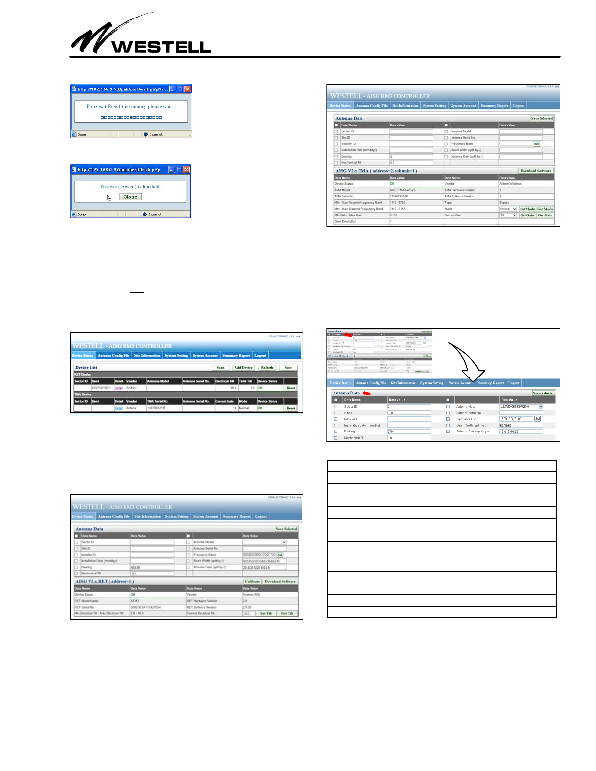
5.1.5 Reset a Device
Use the Reset function on a device that is not operating nor
mally. Reset causes the software on the device to restart and
place it in a state of initialization. Reset may clean device alarm
status temporarily. Click on the Reset button for the device that
you want to reset.
Figure 27. Resetting a Device
Wait for the process to finish.
Section AIS‐RM3‐20B
030‐101806 Rev. A
R
1310IBRA 11
Close the message window.
5.2 Managing and Adjusting AISG Devices
Figure 28 displays a list of devices, in table row format. In the
“Detail” column (for each row of devices or Sector ID's in the
Device List) is a link to a panel to view the details for that partic
ular device. To view the detailed information on a specific device
(a TMA or RET), click on the Detail link of the device in the De
tail column.
Figure 28. Navigating to a Device Shown in Device List
RET Device Details. Clicking on the Detail link for a RET device
opens a page (Figure 29) that shows device‐specific detailed in
formation retrieved from the selected RET device (bottom
half of screen), as well as its antenna data (top half of screen).
Figure 29. Sample RET (and Antenna) Details
TMA Device Details. Clicking on the Detail link for a TMA
device opens a page (Figure 30) that shows device‐specific de
tailed information retrieved from the selected TMA device
(bottom half of screen), as well as its antenna data (top half of
screen).
Figure 30. Sample TMA Device (and Antenna) Details
5.2.1 Antenna Data
The “Antenna Data” section at the top half of a selected device
screen (Figure 31) shows detailed information about the an
tenna connected to the selected AISG device. Table 10 explains
the fields and options in the Antenna Data section or panel.
Figure 31. Top‐Half Antenna Data Area of a Device Screen
}
Field Name Description / Constraint / Options
Sector ID The sector ID.
Site ID Base station site ID.
Installer ID Installer's ID
Installation Date Date in mmddyy format
Bearing Antenna bearing in the range of 0359 degrees
Mechanical tilt Installed mechanical tilt in degrees
Antenna Model Select the antenna model from the dropdown list. If a
model is not in the list, refer to the section on “Antenna
Configuration File” on how to add a new antenna model.
Antenna Serial No. Antenna serial number
Frequency Band Frequency band(s) used by the antenna.
Beam Width Beamwidth for each band in frequency order (separated by /)
Antenna Gain Gain for each band in frequency order (separated by /)
Table 10. Antenna Data Section Fields
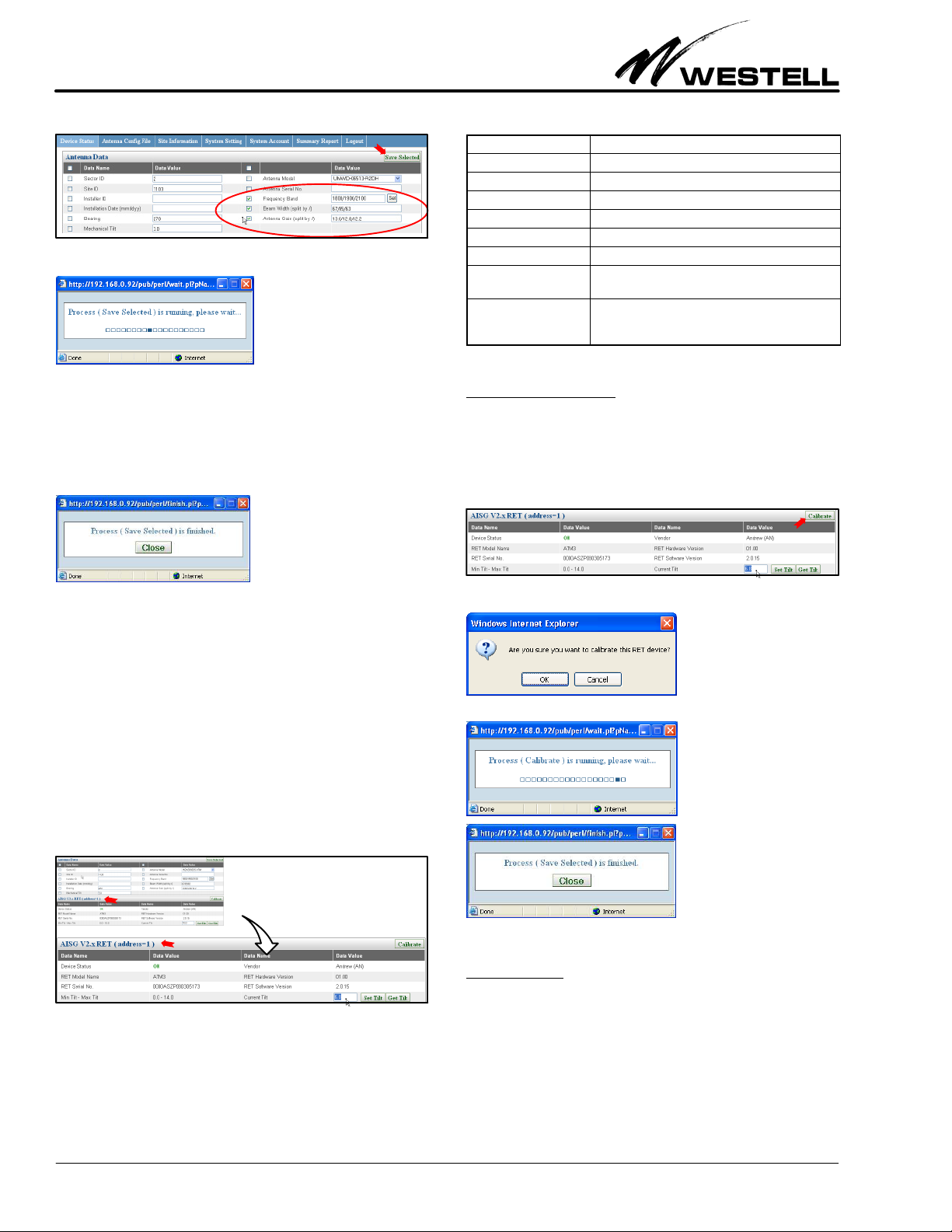
Make entries or changes per company practice, selecting the
items to save to the device. For example, in Figure 32 below, the
items within the red circle are selected. Only these values will be
saved to the device. Click on the Save Selected button to store
those data value(s) in the fields with their check‐boxes selected.
A message box indicates the save command is running.
Section AIS‐RM3‐20B 030‐101806 Rev. A R
1310IBRA
12
Figure 32. Saving Changes in Selected/Changed Fields
After the process is finished, close the message window.
5.2.2 RET Data, Calibration, and Tilt Adjustment
This section covers the RET device details, RET device calibra
tion and tilt angle adjustment. The specific RET device details
and information is displayed in the bottom half of a selected
device panel, as shown Figure 33. The fields in this area are lis
ted in Table 11. The RET table's sub‐heading “AISG V2.x RET”
(or AISG V1.x RET) shows the AISG version supported by the
RET device.
Figure 33. Bottom‐Half RET Data Area of a Device Screen
}
Field Name Description / Constraint / Options
Device Status Displays “OK” or alarm messages
RET Model Name RET model name
RET Serial No. RET serial number
Vendor Vendor name.
RET Hardware Version RET hardware version
RET Software Version RET software version
Min Tilt Max Tilt Allowed electrical down tilt range of the selected an
tenna model
Current Tilt Current electrical tilt. Tilt value must be in the Min Tilt
Max Tilt range. If the tilt value cannot be retrieved,
the data value is empty.
Table 11. RET Device Data / Fields
5.2.2.1 Calibrate Device
After installation of a RET device, calibration causes the actuat
or to be driven through its whole tilt range. Also, sometimes
unforeseen errors require calibration to return a RET device to
a normal status. Click on the Calibrate button (located at the
right side of the subheading row in the bottom half of the selec
ted device panel) to calibrate the RET device.
Figure 34. Activating a Calibrate RET Device Command
Click OK in the confirmation window to initiate the process.
The process will run, and after the process is done, close the mes
sage window.
5.2.2.2 Set Tilt
To change the electrical tilt angle of the antenna, the Set Tilt but
ton in the bottom‐right corner of the selected device panel will
be used. First, type in a value for the tilt angle (within the allowed
range) in the Current Tilt text field, then click on the Set Tilt but
ton.

Section AIS‐RM3‐20B
030‐101806 Rev. A
R
1310IBRA 13
Figure 35. Changing the Electrical Tilt of the Antenna
The following confirmation window is displayed. Click on the
OK button to initiate the process of changing the tilt angle. After
the process is done, close the subsequent message window.
5.2.2.3 Get Tilt
Click on the Get Tilt button in the bottom‐right corner of the se
lected device panel (Figure 36) to get the current electrical tilt
angle of the antenna. The current tilt angle is displayed in a
pop‐up window.
Figure 36. Getting the Tilt of the Antenna
5.2.3 TMA Data, Mode and Gain Adjustment
This section covers TMA device details, the TMA mode, and
TMA gain adjustment for the specific TMA selected from the
device list. Figure 37 displays how to select the link to the specif
ic TMA from the Device List.
Figure 37. Navigating to a TMA Shown in Device List
The specific TMA's data appears in the bottom half of the
screen, the TMA panel (Figure 38), that appears when the De
tail link is clicked. “AISG V1.x” in the TMA subheading at the
top of Figure 38 indicates the AISG version supported by the
TMA device.
Figure 38. Viewing a Specific TMA Shown in Device List
The fields in the selected TMA Device panel are listed in
Table 12.
Field Name Description / Constraint / Options
Device Status Displays “OK” or alarm messages
TMA Model Name TMA model name
TMA Serial No. TMA serial number
Vendor Vendor name.
TMA Hardware Ver
sion
TMA hardware version
TMA Software Ver
sion
TMA software version
Min Max Receive
Frequency Band
Allowed receive frequency band range
Min Max Transmit
Frequency Band
Allowed transmit frequency band range
Gain Resolution Gain increment size between min. and max. gain. For
fixed or nonlinear gain TMA, this value is always zero.
Type Either “Bypass” and/or “VSWR”
Mode TMA mode can either be “Bypass” or “Normal”
Current Gain Value should be in the range Min Gain Max Gain. If the
gain value cannot be retrieved, the data value is empty.
Table 12. TMA Device Data / Fields
5.2.3.1 Set Mode
In the bottom right corner of Figure 38 are four buttons for get
ting and setting the gain and mode of the TMA, as well as
drop‐down menus for changing the mode and current gain. To
set the TMA mode, first select the mode from the “Mode”
dropdown menu (see red arrow in Figure 39), then click on the
Set Mode button to set the newly‐changed TMA mode.

Section AIS‐RM3‐20B 030‐101806 Rev. A R
1310IBRA
14
Figure 39. Setting the TMA Mode
The following confirmation window below appear. Click on the
OK button to initiate the process of changing the TMA mode.
After the process is done, close the subsequent message window.
5.2.3.2 Get Mode
Click on the Get Mode button in the bottom‐right corner of the
selected device panel (shown in Figure 36 and Figure 39) to get
the current TMA mode. The current TMA mode is displayed in
a pop up window, as shown below.
5.2.3.3 Set Gain
Select a TMA gain value in the range Min Gain – Max Gain in
the Current Gain drop‐down menu, then click on the Set Gain
button (shown in Figure 39). The confirmation window below is
displayed. Click on the OK button to initiate the process of chan
ging the TMA gain. After the process is done, close the message
window.
5.2.3.4 Get Gain
Click on the Get Gain button in the bottom‐right corner of the
selected device screen (shown in Figure 36 and Figure 39) to ob
tain the current TMA gain value. The current TMA gain value
is displayed in a pop up window, as shown below.
5.3 Site Information
The Site Information menu allows a user to record site informa
tion. Click on the third tab at the top of the main menu to access
the Site Data panel (see Figure 40). After filling in the site data,
click the Save button to store the information in the AISG‐RM3.
Figure 40. Adding/Updating Site Information
The following process running window is displayed. Click on the
Close button after the process is done, to close the subsequent
message window.

Section AIS‐RM3‐20B
030‐101806 Rev. A
R
1310IBRA 15
5.4 Summary Report
The Summary Report menu, shown in Figure 41, displays an in
formation summary of the AISG‐RM3 controller and enables
downloading of both the summary report and the system access
log report. These two functions are executed by selecting their
buttons near the top right corner of the screen.
System Setting
Action* Information Recorded Description
SET_NET Current IP, Gateway, Sub
Network mask
Network Setting
SET_SCAN_
LENGTH
Current scan length setting
for device scan
Set Scan Length
SET_POWER Current DC 12V/24V setting
and power mode
Power Setting
SET_SYS_TIME Current system date and
time setting
System Time Setting
REBOOT AISG‐RM3 is rebooted
System Account
Action* Information Recorded Description
ADD_USER Which user account is ad
ded
Add User Account
DELETE_USER Which user account is de
leted
Delete User Account
Device Information Initialization
Action* Information Recorded Description
SCAN A scan process is initiated.
ADD_DEV Vendor code and serial no.
of added device
Add Device
SAVE_DEV A save process is initiated for
storing device information to
AISG‐RM3.
RESET_DEV Sector ID Reset Device. Device identi
fied by Sector ID is reset
Device & Antenna Data Setting
Action* Information Recorded Description
SAVE_
SELECTED
Sector ID Save Antenna Data. Selected
antenna data of the device
identified by Sector ID is saved
CONFIGURE_
MODEL
Sector ID Save Antenna Model. Antenna
model of the device identified
by Sector ID is changed.
CALIBRATE Sector ID RET Calibrate. Device identi
fied by Sector ID is calibrated
SET_TILT Sector ID, tilt value Set RET Tilt
SET_GAIN Sector ID, gain value Set TMA Gain
SET_MODE Sector ID, mode Set TMA Mode
*Note: The key word in the Action column is used in the log to represent the recorded action. Information re
lated to an action in the Information Recorded column is also recorded in the log.
Table 13. TMA Device Data / Fields
Summary Report. The summary report includes the detailed in
formation on each device, the site information, and system settings.
Figure 41. Summary Report and Access Log
"
"
Click on the Download Report button (see the solid red arrow in
Figure 41) to store a copy of the summary report in html format.
Click on the Download Access Log button (indicated by the
stripped blue arrow in Figure 41) to download a copy of the sys
tem access history in text format. The access log records the
time, the user, and the type of action that has taken place. Only
actions that pertain to system setting changes, user account ad
dition and deletion, and device setting changes are recorded.
The actions and the corresponding information recorded in the
log are described in Table 13.
6. MANAGING ANTENNA CONFIGURATIONS
The Antenna Config File menu is used to manage antenna con
figuration files for RET antenna model configurations. The
antenna configuration file data establishes the relationship
between the movement of a RET drive system and the beam tilt
position of the antenna. If the model of an antenna connected
to a RET device is not in the AISG‐RM3 controller, then its con
figuration file must be uploaded.
Figure 42. Antenna Configuration File Screen
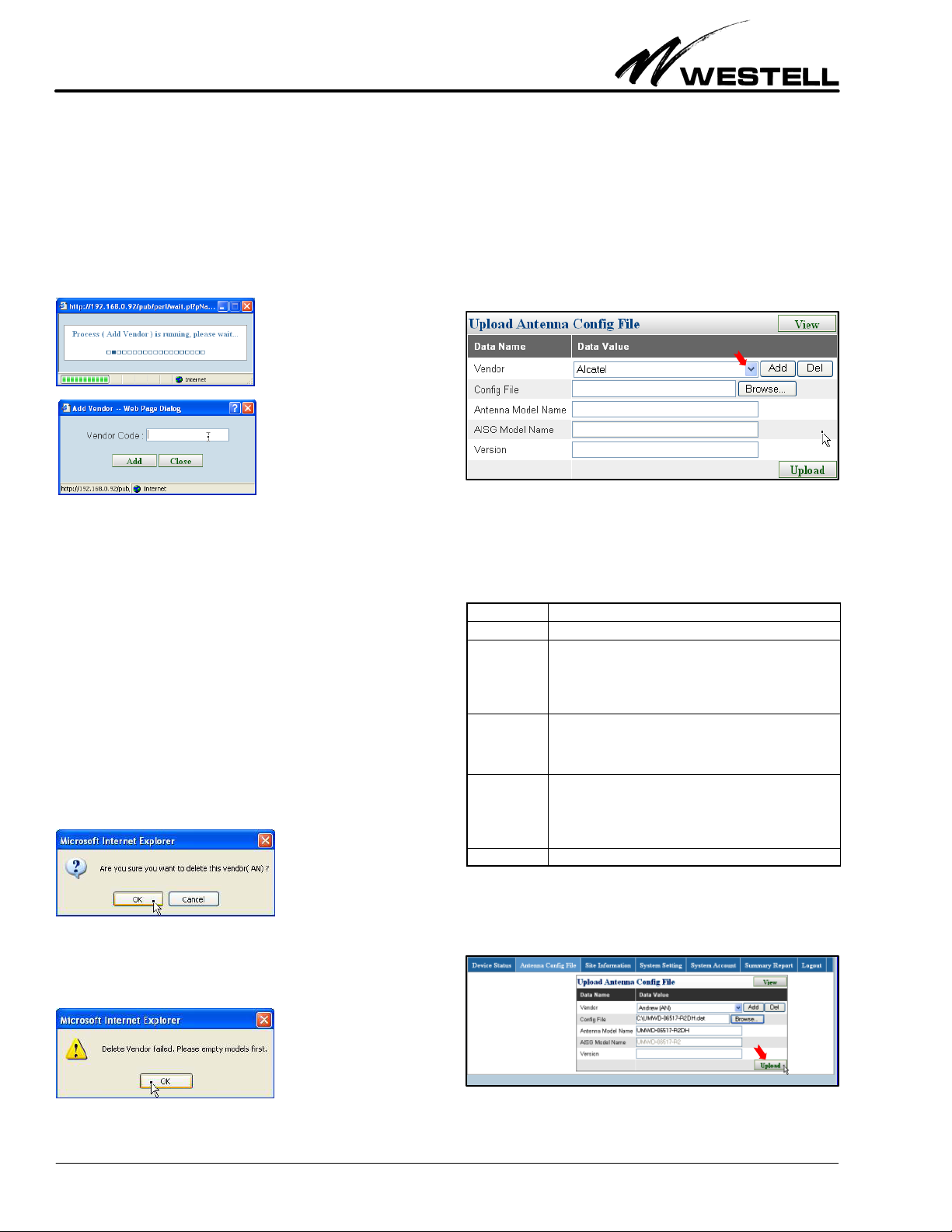
6.1 Adding a Vendor
A vendor ’s name must exist in the Vendor dropdown list before
uploading one of its antenna model configuration files. To add
a new vendor, click on the Add button (see the red arrow in
Figure 42). The window below appears.
This window asks for the two‐character vendor code assigned by
AISG for use in identifying a product’s vendor. The combination
Section AIS‐RM3‐20B 030‐101806 Rev. A R
1310IBRA
16
of Vendor Code and product Serial Number form a unique iden
tity for every antenna line device. The vendor name is
automatically generated based on this vendor code. If you don’t
know your antenna’s vendor code, you can check the AISG web
site (www.aisg.org.uk) or inquire your antenna vendor.
Type in the vendor code and click on the Add button. After the
process is finished, close the message window.
The vendor name should be added to the dropdown list.
6.2 Deleting a Vendor
To remove a vendor from the dropdown list, use the Del button
(see Figure 42). Note that before deleting a vendor, make sure
there are no antenna model configurations from this vendor in
use; that is, the vendor’s antenna model configuration list should
be empty.
From the Vendor dropdown menu, select the vendor that is to
be deleted and click the Del (delete) button. The confirmation
window below is displayed; confirm to remove the vendor from
the drop‐down vendor list.
If the vendor ’s antenna model configuration is in use, the follow
ing warning message will appear and the vendor is not deleted.
6.3 Antenna Model Management
6.3.1 Upload Antenna Configuration File
The vendor ’s name must be in the vendor dropdown list before
its antenna model configuration files can be uploaded. If a
vendor owns more than one vendor code, the vendor code is also
shown after the vendor name. Select the vendor name with the
right vendor code to upload the configuration file. The vendor
code must match the vendor code on the RET device.
Figure 43. Selecting a Vendor in the Upload Antenna ConFig
File Panel of the Antenna Configuration File Menu
The following table explains what information must be provided
for the other fields in this panel.
Field Name Description / Constraint / Options
Vendor Vendor name
Config File A filename with its full path should be provided. Use the
Browse button to locate the file. Only files with an extension of
.bin or .acf are allowed. File extensions .dat or .acu may also
be allowed depending on the vendor. File size must be less
than 0.5KB.
Antenna Model
Name
The configuration file's filename is automatically used as the
Antenna Model Name. You can modify this name to what you
want shown in the AISG‐RM3. This name may be longer than
15 characters.
AISG Model
Name
This model name is limited to 15 characters according to the
AISG standard. Antenna Model names that are longer should
be mapped to a version that is less than 15 characters. You
may need to enter this model name manually. This mapping
should be recorded for future reference.
Version The antenna model configuration file version (Optional)
Table 14. Antenna Configuration Data / Fields
Enter the correct data per company practice. Click on the Up
load button in the panel after filling in the required information.
Figure 44. Adding a new Antenna Configuration File
Section AIS‐RM3‐20B
030‐101806 Rev. A
R
1310IBRA 17
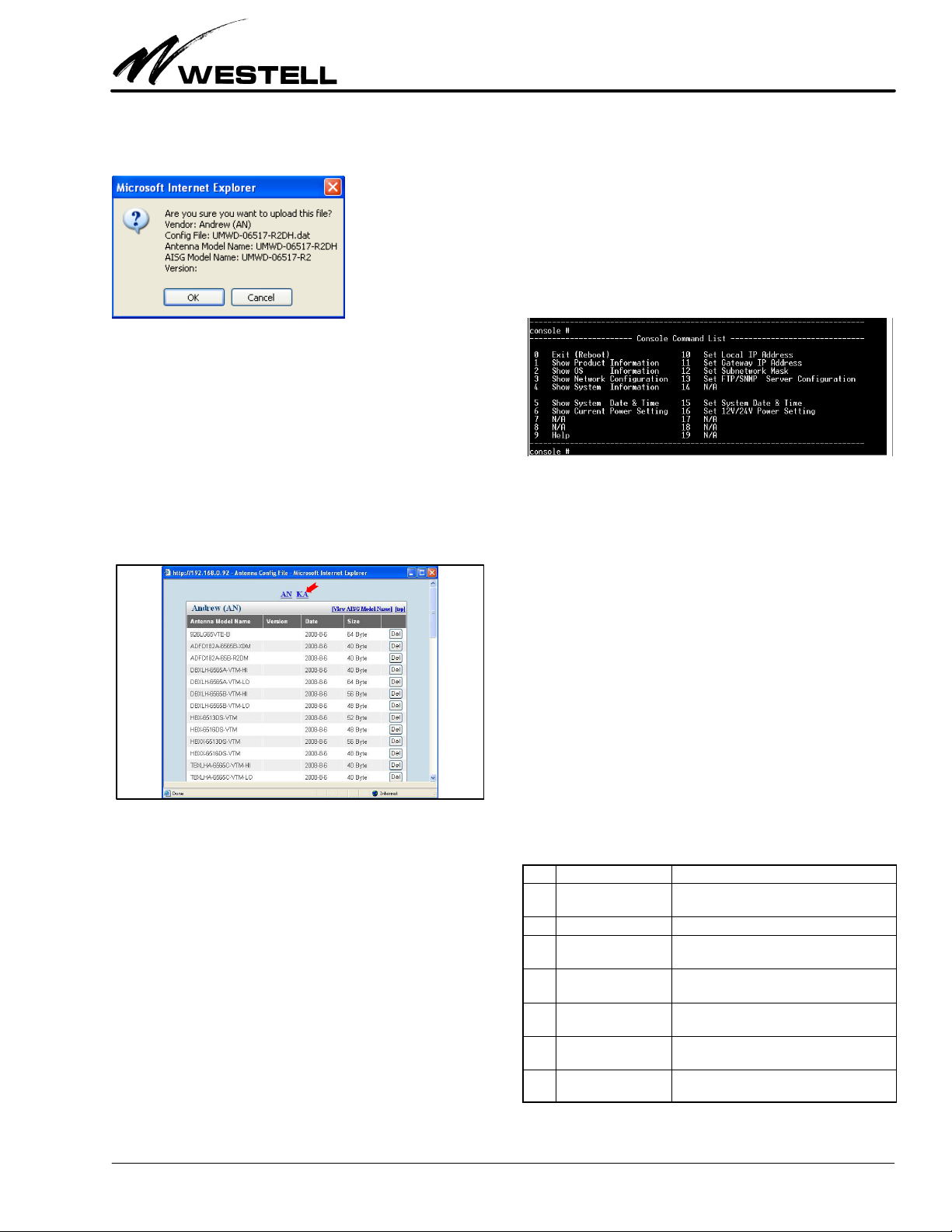
The confirmation window appears with the entered informa
tion. Click the OK button to initiate the upload process.
When the process is finished, click the Close button to close the
message window.
6.3.2 Deleting an Antenna Model
This section describes how to delete an antenna model from the
AISG‐RM3 controller.
Click the View button (in the Antenna Config File menu shown
in Figure 44) to display the entire list of antenna models stored
in the AISG‐RM3. Click on the vendor code (see the red arrow
in Figure 45) to go to the listing belonging to that vendor.
Figure 45. Entire List of Antenna Models
To delete an antenna model, find the antenna model name in the
list and click the Del button (in the same row) corresponding to
that model.
7. USING THE CONSOLE INTERFACE
The purpose of the console access using a direct connection is to
provide a means to change system settings in the event that the
AISG‐RM3 controller cannot be otherwise accessed (for ex
ample, forgetting the IP address of AISG‐RM3).
7.1 How to Set Up Console Access
To set up a direct connection, connect a serial cable from a PC’s
COM port to the RS232C port of the AISG‐RM3 controller.
Use a terminal software program, such as the Hyperterminal
program provided in MS Windows, to connect with the
AISG‐RM3 controller. Set the terminal connection settings to:
Baud Rate = 9600 Stop bits = 1
Data bits = 8 No Parity
7.2 Using Console Commands
Once connection with the AISG‐RM3 controller is established,
the following is displayed:
Figure 46. Console Command List
Commands are numbered from 0 to 19, and some commands are
reserved for future use.
To execute a command that changes data, follow the steps below.
1. Enter the number corresponding to a command first.
2. If a data value is expected for a command, then enter the
data value associated with that command. Leave it blank to
keep the original value.
3. Reboot the system when making changes to settings, such
as the IP, to apply the changes.
To display information on a command, enter the corresponding
number.
7.3 Viewing System Information
The following table shows commands that are used to display in
formation.
No. Command Description
1Show Product Informa
tion
Displays the product model and serial number
of the AISG‐RM3 controller.
2Show OS Information Displays the OS version and memory, etc.
3Show Network Config
uration
Displays the IP address of the AISG‐RM3 con
troller, the Gateway IP, and Subnet mask.
4Show System Informa
tion
Displays the hardware and software version of
the AISG‐RM3 controller.
5Show System Date &
Time
Displays the current system UTC date and
time.
6Show Current Power
Setting
Displays the on/off status of AISG 12V and 24V
DC.
9Help For an explanation on how to use a command
to make changes.
Table 15. Command Display Numbers

Section AIS‐RM3‐20B 030‐101806 Rev. A R
1310IBRA
18
Figure 47. Viewing System Information via Command No.
7.4 Setting System Parameters
The following table describes the commands that are used to
change parameter settings.
No. Command Description
10 Set Local IP Address Changes the IP address of the AISG‐RM3 con
troller. Reboot for changes to take effect.
11 Set Gateway IP Ad
dress
Assigns the Gateway IP. Reboot for changes to
take effect.
12 Set Subnetwork
Mask
Assigns the subnetwork mask. Reboot for
changes to take effect.
15 Set System Date &
Time
Changes the system UTC date and time.
16 Set 12v/24v Power
Setting
Switches 12V/24V DC on or off. The default is “N”
which represents “off”.
Table 16. Command Display Numbers
If no data value is entered for that command, the original value
is kept.
Figure 48. Commands to Set System Parameters
7.5 Rebooting the AISG‐RM3 Controller
Reboot the controller if a system parameter has changed or if a
problem has occurred that affects normal operation.
Enter “0”, then enter “y” to reboot the AISG‐RM3 controller.
If command “0” is chosen by accident, do not enter “y” and you
will be brought back to the command list.
Figure 49. Commands to Reboot the Controller
Figure 50. Software Upgrade Screen
1.
2.
3.
4.

Section AIS‐RM3‐20B
030‐101806 Rev. A
R
1310IBRA 19
8. PERFORMING FIRMWARE UPGRADES
Follow the steps below to perform firmware upgrades for the
controller.
1. From the System Setting menu (Item # 1 in Figure 50),
click on the [Software Upgrade] button (Item #2). In the
subsequent pop‐up screen, browse and choose the firm
ware to be upgraded (Item # 3). Press the [Start Software
Upgrade] button (Item #4) to start the software upgrade.
2. Upgrading will take about 20 seconds, depending on the
network speed for uploading the firmware. Once finished,
perform a manual reboot of the controller.
3. Refresh the browser to reload the user interface; you will
find the changed/upgraded firmware.
9. ERROR & ALARM CODES/MESSAGES
The following (Table 17) are the error codes and alarm codes
and messages for the controller. Please refer to AISG standard
for the description of codes 0x00 ~ 0x27.
10. CUSTOMER & TECHNICAL SERVICES
If technical or customer assistance is required, contact Westell
by calling or using one of the following options:
Voice: (800) 377‐8766
email: [email protected]
For additional information about Westell, visit the Westell
World Wide Web site at http://www.Westell.com.
Figure 51. Rebooting After Software/Firmware Upgrade
1.
2.

Section AIS‐RM3‐20B 030‐101806 Rev. A R
1310IBRA
20
Code Message Alarm Description
0x00 OK
0x01 Actuator Detection Fail X
0x02 Actuator Jam Permanent X
0x03 Actuator Jam Temporary X
0x04 Block Number Sequence Error
0x05 Busy
0x06 Checksum Error
0x07 Command Sequence Error
0x08 Data Error
0x09 Device Disabled
0x0A EEPROM Error X
0x0B Fail
0x0C Flash Erase Error X
0x0D Flash Error X
0x0E Not Calibrated X
0x0F Not Scaled X
0x11 Other Hardware Error X
0x12 Other Software Error X
0x13 Tilt out of Range X
0x14 Position Lost X
0x15 RAM Error X
0x16 Segment Number Sequence Error
0x17 UART Error X
0x19 Unknown Command
0x1A TMA Alarm Minor X
0x1B TMA Alarm Major
0x1C Gain out of Range
0x1D Read Only
0x1E Unknown Parameter
0x1F Bypass Mode
0x21 Software Missing
0x22 Invalid File Content
0x24 Format Error
0x25 Unsupported Proc
0x26 Invalid Proc Sequence
0x27 Actuator Interference X
0x51 Uninitialized X Cannot get device information after a scan process.
0x52 Bad Responding XBad communication between the AISG‐RM3 system and the device.
0x53 No Responding XLost connection between the AISG‐RM3 system and the device.
0x54 Function Fail Unexpected result from the AISG‐RM3 system.
0x59 Timeout The response time from the device to the AISG‐RM3 has timed out.
0x70 Default Result Unexpected or unknown result.
0x71 Error General error.
0x72 File I/O fail File access fails.
0x73 System Timeout Waiting for response from the AISG‐RM3 has timed out.
0x77 Add device fail Failed to add a device.
0x78 Value is empty Input field does not allow empty value.
0x79 Field name is null! Invalid field name is used on the web interface.
0x7A Antenna model config file does not exist! The antenna configuration data file doesn't exist.
0x7B Device exists! The device already exists in the AISG‐RM3 system.
0x7C Size is too large! The file size of antenna configuration data is too large.
0x7D The max. number of files reached! The number of antenna configuration data files has reached the limits defined in the
controller system.
0x7E Total file size exceeds The total file size of antenna configuration data files in the controller system has
reached the limits defined in the system.
Table 17. Error and Alarm Codes
Table of contents
Other Westell Controllers manuals


Popular Controllers manuals by other brands

Advantech
Advantech LNC-5800D Hardware Maintenance Manual

ATI Technologies
ATI Technologies DKG-M Installation and operation manual

BZ PRODUCTS
BZ PRODUCTS M20+ installation manual

Carel
Carel supernode Technical leaflet

WEISS
WEISS FV663 Installation & operation instructions

Contemporary Research
Contemporary Research ICC2-IRC product manual


Adaptec
Adaptec PowerDomain 29160 installation guide

Gira
Gira KNX 2139 00 Product documentation

LAE
LAE SMD34RU Instructions for installation and use

GOK
GOK FL 90-4 Assembly and operating manual

Nicotra Gebhardt
Nicotra Gebhardt FAN Commander 200 operating manual

Curtis Instruments
Curtis Instruments PMC 1200 Series manual