Gira KNX 2139 00 Operator's manual

Product documentation
Issue:
21.06.2022
21393100
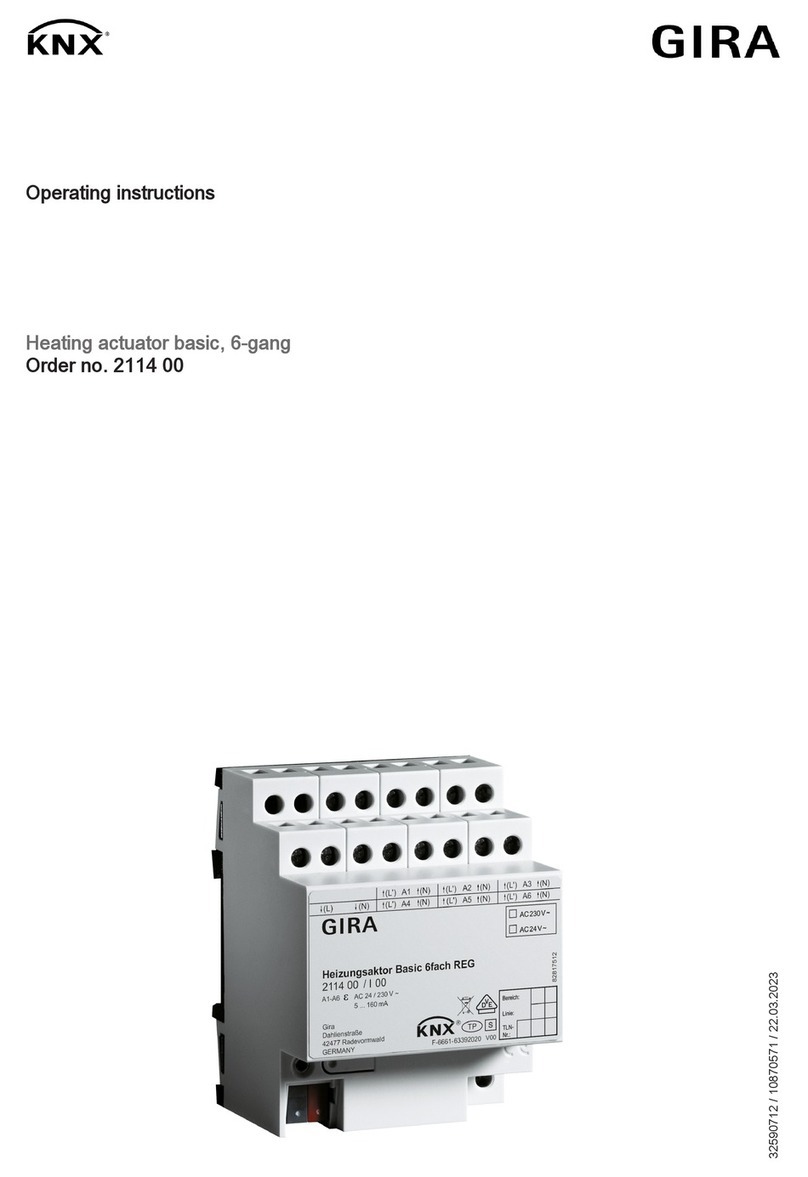
Heating actuator 6-gang with controller
Order no. 2139 00

Table of Contents
Heating actuator 6-gang with controller | Order no. 2139 00 | 21393100 Page 2 of 257
Table of Contents
1 Information on the product ................................................................................................6
1.1 Product catalogue.................................................................................................. 6
1.2 Function ................................................................................................................. 6
1.3 Device components ............................................................................................. 10
1.4 Technical data...................................................................................................... 11
2 Safety instructions...........................................................................................................12
3 Mounting and electrical connection.................................................................................13
4 Commissioning................................................................................................................15
5 Application programs ......................................................................................................17
6 Scope of functions...........................................................................................................18
7 Notes on software ...........................................................................................................21
8 Operation and indication .................................................................................................22
8.1 Button operation and indication functions............................................................ 22
8.2 ETS configuration ................................................................................................ 28
8.2.1 Manual operation.....................................................................................28
8.2.2 Status indication ......................................................................................31
8.3 Operation and indication parameters................................................................... 33
8.4 Operation and indication object list...................................................................... 36
9 Valve outputs ..................................................................................................................37
9.1 Priorities for valve outputs.................................................................................... 37
9.2 Channel configuration.......................................................................................... 38
9.2.1 Channel configuration parameters ..........................................................39
9.3 Channel-independent functions ........................................................................... 39
9.3.1 Heat requirement.....................................................................................39
9.3.2 Pump control ...........................................................................................44
9.3.3 Largest command value ..........................................................................50
9.3.4 Summer / winter mode switchover ..........................................................54
9.3.5 Service mode...........................................................................................57
9.3.6 Failure of the valve operating voltage......................................................61
9.4 Valve output - General......................................................................................... 63
9.4.1 Name .......................................................................................................63
9.4.2 Data formats for command values........................................................... 64
9.4.3 PWM cycle time.......................................................................................70
9.4.4 Valve direction of action ..........................................................................72
9.4.5 Reset behaviour ......................................................................................73

Table of Contents
Heating actuator 6-gang with controller | Order no. 2139 00 | 21393100 Page 3 of 257
9.4.6 "Valve output - General" parameters.......................................................75
9.4.7 Objects for "Valve output - General"........................................................80
9.5 Cyclical command value monitoring / emergency operation................................ 81
9.5.1 Command value monitoring / emergency operation parameters............. 84
9.5.2 Objects for command value monitoring / emergency operation ..............85
9.6 Command value limit ........................................................................................... 85
9.6.1 Command value limit parameters............................................................ 87
9.6.2 Objects for command value limit .............................................................88
9.7 forced position...................................................................................................... 88
9.7.1 "Forced position" parameters ..................................................................90
9.7.2 Objects for forced position.......................................................................92
9.8 Command value status ........................................................................................ 92
9.8.1 Status parameters ...................................................................................96
9.8.2 Objects for status.....................................................................................97
9.9 Short-circuit and overload detection .................................................................... 98
9.9.1 Short-circuit and overload detection parameters................................... 104
9.9.2 Objects for short-circuit and overload detection ....................................105
9.10 Valve rinsing ...................................................................................................... 105
9.10.1 Valve rinsing parameters.......................................................................109
9.10.2 Objects for valve rinsing ........................................................................111
9.11 Operating hours counter .................................................................................... 112
9.11.1 Operating hours counter parameters.....................................................117
9.11.2 Objects for operating hours counter ......................................................119
10 Room temperature controller ........................................................................................121
10.1 Channel configuration........................................................................................ 121
10.1.1 Channel configuration parameters ........................................................121
10.2 Room temperature controller - General ............................................................. 122
10.2.1 Name .....................................................................................................122
10.2.2 Operating mode.....................................................................................122
10.2.3 Type of control.......................................................................................124
10.2.4 Disabling functions ................................................................................134
10.2.5 Reset behaviour ....................................................................................135
10.2.6 "Room temperature controller - General" parameters ...........................135
10.3 Operating mode and setpoints........................................................................... 138
10.3.1 Operating mode and setpoint parameters .............................................153
10.3.2 Objects for operating mode and setpoints.............................................159
10.4 Command value output and command value limit............................................. 164
10.4.1 Command value output parameters ......................................................167

Table of Contents
Heating actuator 6-gang with controller | Order no. 2139 00 | 21393100 Page 4 of 257
10.4.2 Command value limit parameters.......................................................... 169
10.4.3 Objects for command value output and command value limit ...............170
10.4.4 Objects for command value limit ...........................................................181
10.5 Room temperature measurement...................................................................... 181
10.5.1 Temperature measurement parameters................................................ 185
10.5.2 Objects for temperature measurement.................................................. 187
10.6 Controller status................................................................................................. 187
10.6.1 Status output parameters ......................................................................190
10.6.2 Objects for controller status...................................................................191
10.7 Boost function .................................................................................................... 193
10.7.1 Boost function parameters.....................................................................194
10.7.2 Objects for boost function......................................................................195
10.8 Floor temperature monitoring............................................................................. 196
10.8.1 Floor temperature monitoring parameters .............................................197
10.8.2 Objects for floor temperature monitoring ...............................................198
10.9 Setpoint temperature limit, cooling..................................................................... 199
10.9.1 Setpoint temperature limit parameters ..................................................201
10.9.2 Objects for setpoint temperature limit.................................................... 202
10.10 Setpoint temperature increase, heating............................................................. 203
10.10.1Setpoint temperature increase parameters ...........................................205
10.10.2Objects for setpoint temperature increase.............................................206
10.11 Scenes............................................................................................................... 206
10.11.1Scene parameters .................................................................................210
10.11.2Objects for scenes.................................................................................212
11 Logic functions ..............................................................................................................213
11.1 Logic functions parameters................................................................................ 214
11.2 Logic gate .......................................................................................................... 216
11.2.1 Logic gate parameters...........................................................................218
11.2.2 Logic gate object list ..............................................................................221
11.3 Converter (1 bit -> 1 byte).................................................................................. 223
11.3.1 Converter parameters............................................................................224
11.3.2 Converter object list...............................................................................226
11.4 Disabling element [Filtering/Time]...................................................................... 227
11.4.1 Disabling element parameters............................................................... 229
11.4.2 Disabling element object list ..................................................................233
11.5 Comparator........................................................................................................ 234
11.5.1 Comparator parameters ........................................................................236
11.5.2 Comparator object list............................................................................242

Table of Contents
Heating actuator 6-gang with controller | Order no. 2139 00 | 21393100 Page 5 of 257
11.6 Limit value switch............................................................................................... 245
11.6.1 Limit value switch parameters ...............................................................247
11.6.2 Limit value switch object list ..................................................................253
12 As-delivered state .........................................................................................................256

Information on the product | Product catalogue
Heating actuator 6-gang with controller | Order no. 2139 00 | 21393100 Page 6 of 257
1Information on the product
1.1 Product catalogue
Product name: Heating actuator 6-gang with controller
Use: Actuator
Design: RMD (rail-mounted device)
Order no. 2139 00
1.2 Function
General
The heating actuator is used for the activation of electrothermal actuators (ETA) for
heating or cooling systems. It possesses 6 electronic outputs, each of which can si-
lently activate up to 4 (AC 230 V) or 2 (AC 24 V) actuators. Both deenergised closed
and deenergised opened actuators can be connected.
In addition, the actuator contains up to 12 room temperature controllers (RTC), which
are integrated in the device software and which work independently of the process.
The command value outputs of these controllers can be linked to the electronic valve
outputs of the actuator, meaning that temperature control and valve activation can
take place using just one bus device, if required. The use of external room temperat-
ure controllers (e.g. push-button sensors with RTC) is thus not absolutely essential,
but is possible as the valve outputs can be activated individually via the KNX. The in-
tegrated controllers can also activate other heating actuators or fan coil actuators.
The room temperature is made available to the integrated controllers via separate
communication objects. All the controller functions (e.g. setpoint temperature spe-
cification, operating mode switchover, switchover of the operating mode) are con-
trolled via KNX communication objects (object controller without its own operating
elements), meaning that controller operation is possible via controller extensions or
visualisations.
Functions of the electronic valve outputs
The heating actuator receives 1-bit or 1-byte command value telegrams, transmitted,
for example, by external KNX room temperature controllers or by one of the internal
controllers. The actuator controls its valve outputs either in switching form or with a
PWM signal, according to the data format of the command values and the configura-
tion in the ETS. The cycle time for constant PWM output signals can be configured
separately for each valve output of the heating actuator. This allows individual adapt-
ation to different actuator types.
On activation with constant command values, an optional command value limit can
be configured, which allows the limitation of received command values at the "Min-
imum" and "Maximum" limits. A minimum command value can be used, for example,
for the implementation of basic heating or cooling. A maximum command value al-
lows the limitation of the effective command value range, which usually has a positive
influence on the lifespan of actuators.

Information on the product | Function
Heating actuator 6-gang with controller | Order no. 2139 00 | 21393100 Page 7 of 257
The heating actuator possesses a heat requirement and pump controller. This pro-
duces a positive impact on the energy consumption of a housing or commercial build-
ing through the transmission and evaluation of the largest command value in the
heating or cooling system. The information on the largest active command value can
be made available to suitable calorific furnaces with integrated KNX controller directly
via a KNX telegram (1-byte constant), for example, to determine the optimum flow
temperature. Alternatively or additionally, the heating actuator can even evaluate the
command values of its outputs and make general heat requirement information avail-
able in the form of limiting value monitoring with hysteresis (1-bit, switching). Using a
KNX switch actuator, this allows the energy-efficient activation of burner and boiler
controllers with suitable control inputs (e.g. requirement-orientated switchover
between the reduction and comfort setpoint in a central combi boiler).
The heating actuator also allows switching activation of the circulation pump of the
heating or cooling circuit via a 1-bit KNX telegram. When using pump control, the
pump is only switched on by the actuator when at least one command value of the
outputs exceeds a limiting value with hysteresis defined in the ETS. The pump is
switched off when the limiting value is reached or undershot again. This saves elec-
trical energy, as the pump is only activated by sufficiently large, and thus effective,
command values. Optional cyclical anti-sticking protection prevents the sticking of the
pump, if it has not been switched on by the command value evaluation for a longer
period of time.
To prevent calcification or sticking of a valve which has not been activated for some
time, the actuator has an automatic valve rinsing function. Valve rinsing can be ex-
ecuted cyclically or using a bus command, causing the activated valves to run
through the full valve stroke for a preset period of time. If necessary, the intelligent
valve rinsing can be enabled. In so doing, cyclical rinsing using the full stroke is only
executed when a defined minimum command value limiting value was not exceeded
during actuator operation.
Cyclical monitoring of the command values can be performed as an option. If, during
active cyclical monitoring, there are no command value telegrams during a preset
time, then emergency operation is activated for the affected valve output, for which a
configurable constant PWM command value can be preset. In addition, it is possible
to activate a forced position separately for each output using a 1-bit KNX object. A
defined PWM command value is set at the appropriate output.
Emergency operation and forced position can also be activated automatically in case
of bus voltage failure, after bus voltage return or after an ETS programming opera-
tion. If necessary, the command values for emergency operation and the forced posi-
tion can be influenced by the summer and winter mode of the actuator, allowing the
activation of different heating or cooling levels according to the season. The actuator
permits switchover between summer and winter mode at any time using a 1-bit ob-
ject.
The heating actuator possesses comprehensive status functions. The active com-
mand value can be made available as status information, separately for each valve
output.
The actuator is able to detect an overload or a short-circuit at the valve outputs and,
in consequence, to protect them against destruction. Outputs which have experi-
enced a short-circuit or a constant load are deactivated after an identification period.

Information on the product | Function
Heating actuator 6-gang with controller | Order no. 2139 00 | 21393100 Page 8 of 257
In this case, a short-circuit or overload signal can be transmitted via a KNX commu-
nication object. The actuator can also signal a failure of the valve voltage on the
KNX.
The switch-on times of the valve outputs can be detected and evaluated separately
by operating hours counters. In addition, service operation is available, which, during
maintenance or installation, can move all assigned valve drives to a defined position
(completely opened or completely closed) and can lock them against activation by
command value telegrams. Both service mode and the locking status are preset by a
2-bit forced operation telegram.
Function of the room temperature controller
There are 12 controllers integrated into the device's software that can be used for in-
dividual room temperature control. This allows the temperature to be set in up to 12
rooms or room areas to specified setpoints through independent control processes.
Depending on the operating mode, current setpoint temperature and room temperat-
ure, using a controller means that a command value for heating or cooling control
can be transmitted to the KNX for the control circuit or be forwarded internally to a
valve output. The controller distinguishes between different operating modes (Com-
fort, Standby, Night, Frost/heat protection) each with their own temperature setpoints
for heating or cooling. For heating and cooling functions, you can select continuous
or switching PI or switching 2-point feedback control algorithms.
In addition to the basic level heating or cooling, activating an additional level enables
an additional heating or cooling unit to be used. In this connection, you can set the
temperature setpoint difference between the basic and the additional level by a para-
meter in the ETS. For major deviations between the temperature setpoint and the ac-
tual temperature, you can activate this additional level to heat up or cool down a
room faster. You can assign different control algorithms to the basic and additional
levels.
The room temperatures are recorded per controller by one or optionally by two ex-
ternal KNX temperature sensors (e.g. push-button sensors with temperature meas-
urement).
Logic functions
In addition, the device has 8 internal logic functions. Using these functions, logic
gates (e.g. AND, OR, exclusive OR, each with up to 4 inputs) can be set up and thus
switching and status information can be linked and evaluated. Alternatively, a 1-bit to
1-byte converter and a disabling element with filter and time functions can be con-
figured for each logic function. As a further option, comparators or limit value
switches with hysteresis can be set as a logic function.
The logic functions have their own KNX communication objects and can process tele-
grams of the actuator or of other bus devices.
Update capability
The device can be updated. Firmware can be easily updated with the Gira ETS Ser-
vice App (additional software).

Information on the product | Function
Heating actuator 6-gang with controller | Order no. 2139 00 | 21393100 Page 9 of 257
KNX Data Secure
The device is KNX Data Secure capable. KNX Data Secure offers protection against
manipulation in building automation and can be configured in the ETS project. De-
tailed specialist knowledge is required. A device certificate, which is attached to the
device, is required for safe commissioning. During mounting, it is recommended to
remove the certificate from the device and to store it securely.
ETS versions
Planning, installation and commissioning of the device are carried out with the aid of
the ETS5, version 5.7.7 or higher or of the ETS6, version 6.0.3 or higher.
Operation
The operating elements (4 push-buttons) on the front panel of the device permit influ-
encing of the electronic outputs of the actuator through manual operation, even
without KNX bus voltage or in a non-programmed state (switch on and off / PWM).
This feature permits a fast function check of the connected actuators. Moreover, the
statuses of the outputs in case of bus voltage failure or bus voltage return and after
ETS programming can be set separately.
Mounting and electrical connection
The device electronics and the bus coupler are supplied from the bus voltage. The
valve outputs possess a separate connection for the supply of the connected actuat-
ors (AC 24 V or AC 230 V).
The device is designed for mounting on DIN rails in closed compact boxes or in dis-
tributors in fixed installations in dry interior rooms.
We recommend using electrothermal actuators of make Gira or, alternatively,
models of make Möhlenhoff (AA2004, AA4004) or Sauter (MTX). Always ob-
serve the technical data of the actuators and compare them with the technical
properties of the heating actuator.

Information on the product | Device components
Heating actuator 6-gang with controller | Order no. 2139 00 | 21393100 Page 10 of 257
1.3 Device components
Image1: Front view
(1) Supply of electrothermal valve drives
(2) Connection of electrothermal valve drives (A1 to A6)
(3) Status LEDs for outputs
(4) Button field for manual operation
(5) Programming button and LED
(6) Bus connection
If all of the status LEDs (3) are flashing (2 Hz), the device is indicating that
there is no power supply to the electrothermal valve drives (1).

Information on the product | Technical data
Heating actuator 6-gang with controller | Order no. 2139 00 | 21393100 Page 11 of 257
1.4 Technical data
KNX
KNX medium TP256
Commissioning mode S-mode
Rated voltage KNX DC 21 ... 32 V SELV
Current consumption KNX 4.5 ... 10 mA
Ambient conditions
Ambient temperature -5 ... +45 °C
Storage/transport temperature -25 ... +70 °C
Heating outputs
Contact type Semi-conductor (Triac), ε
Switching voltage AC 24 / 230 V ~
Mains frequency 50 / 60 Hz
Switching current 5 ... 160 mA
Switch-on current max. 1.5 A (2 s)
Switch-on current max. 0.3 A (2 min)
Number of drives per output
230 V drives max. 4
24 V drives max. 2
Housing
Installation width 72 mm / 4 HP
Connection of outputs
Connection mode Screw terminal
Single stranded 0.5 ... 4 mm²
Finely stranded without conductor sleeve 0.5 ... 4 mm²
Finely stranded with conductor sleeve 0.5 ... 2.5 mm²
Connection torque, screw terminals max. 0.8 Nm

Safety instructions
Heating actuator 6-gang with controller | Order no. 2139 00 | 21393100 Page 12 of 257
2Safety instructions
Electrical devices may only be mounted and connected by electrically skilled
persons.
Failure to observe the instructions may cause damage to the device and result in fire
and other hazards.
Danger of electric shock. Device is not suitable for disconnection from supply
voltage. The load is not electrically isolated from the mains even when the device is
switched off.
Danger of electric shock. Always disconnect before carrying out work on the device
or load. In so doing, take all the circuit breakers into account, which support danger-
ous voltages to the device and or load.
Danger of electric shock. Make sure during the installation that there is always suffi-
cient insulation between the mains voltage and the bus. A minimum distance of at
least 4 mm must be maintained between bus conductors and mains voltage cores.
The device may not be opened or operated outside the technical specifications.

Mounting and electrical connection
Heating actuator 6-gang with controller | Order no. 2139 00 | 21393100 Page 13 of 257
3Mounting and electrical connection
DANGER!
Electric shock when live parts are touched.
Electric shocks can be fatal.
Before carrying out work on the device or load, disengage all the corresponding cir-
cuit breakers. Cover up live parts in the working environment.
Mounting the device
– Enter or scan the device certificate and add it to the project. A high resolution
camera should be used to scan the QR code.
– The device certificate should be removed from the device during mounting.
– Document all passwords and keep them safe.
Observe ambient temperature. Ensure adequate cooling.
■ Mount device on DIN rail.
Connecting the device
Connect either AC 230 V or AC 24 V valve drives to all the outputs.
Only connect valve drives with the same characteristics to each output (deenergised
closed/opened).
Do not connect any other loads.
Connect valve drives for frost-sensitive rooms to outputs A1 and A4. These are
switched off last in the event of overload.
Do not exceed maximum number of valve drives per output (siehe Kapitel "Technical
data" } Page 11).
Observe the technical data of the valve drives used.
Do not connect the neutral conductor from the output terminals through to additional
devices.
■ Connect AC 230 V valve drives according to the connection diagram
(see figure 2).

Mounting and electrical connection
Heating actuator 6-gang with controller | Order no. 2139 00 | 21393100 Page 14 of 257
Image2: Connection of 230 V valve drives
■ Connect AC 24 V valve drives according to the connection diagram
(see figure 3).
Image3: Connection of 24 V valve drives
■ Connect the supply for the valve drives to the terminals 8(L) and 8(N) (1).
■ Connect bus line with device connection terminal.

Commissioning
Heating actuator 6-gang with controller | Order no. 2139 00 | 21393100 Page 15 of 257
4Commissioning
The device is commissioned with the ETS version 5.7.7 or higher.
Safe-state mode
The safe-state mode stops the execution of the loaded application program.
Only the system software of the device is still functional. ETS diagnosis func-
tions and programming of the device are possible. Manual operation is not
possible.
Activating safe-state mode
■ Switch off the bus voltage or remove the KNX device connection terminal.
■ Wait about 15 s.
■ Press and hold down the programming button.
■ Switch on the bus voltage or attach the KNX device connection terminal. Re-
lease the programming button only after the programming LED starts flashing
slowly.
The safe-state mode is activated.
By briefly pressing the programming button again, the programming mode can
also be switched on and off in the safe-state mode as usual. If the program-
ming mode is active, the programming LED stops flashing.
Deactivating safe-state mode
■ Switch off bus voltage (wait approx. 15 s) or carry out ETS programming.
Master reset
The master reset restores the basic device settings (physical address 15.15.255,
firmware remains in place). The device must then be recommissioned with the ETS.
Manual operation is possible.
In secure operation: A master reset deactivates device security. The device can then
be recommissioned with the device certificate.
Performing a master reset
Precondition: The safe-state mode is activated.
■ Press and hold down the programming button for > 5 s.
The programming LED flashes quickly.
The device performs a master reset, restarts and is ready for operation again
after approx. 5 s.

Commissioning
Heating actuator 6-gang with controller | Order no. 2139 00 | 21393100 Page 16 of 257
Restoring the device to factory settings
Devices can be reset to factory settings with the Gira ETS Service App. This function
uses the firmware contained in the device that was active at the time of delivery (as-
delivered state). Restoring the factory settings causes the devices to lose their phys-
ical address and configuration.

Application programs
Heating actuator 6-gang with controller | Order no. 2139 00 | 21393100 Page 17 of 257
5Application programs
ETS search paths: heating, air condition / valves / Heating actuator, 6-gang with
controller
Application:
Name Heating actuator 6-gang 20E021
Version 2.1 for ETS5 version 5.7.7 or higher and ETS6 version 6.0.3 or
higher
from mask version SystemB (07B0)
Summarized de-
scription
Multifunctional heating actuator application:
Activation of up to 6 valve outputs for electrothermal actuators.
Optionally with room temperature control through 12 integrated
room temperature controllers. With logic functions and manual
operation. KNX Data Secure capable.

Scope of functions
Heating actuator 6-gang with controller | Order no. 2139 00 | 21393100 Page 18 of 257
6Scope of functions
Valve outputs
– 6 independent electronic valve outputs.
– Valve activation (deenergised opened / closed) can be configured for each
output.
– Command value evaluation as "Switching, 1-bit", "Constant, 1-byte" or "Con-
stant, 1-byte with command value limiting value and hysteresis".
– With a 1-byte command value, the outputs are activated by pulse width modu-
lation (PWM). The cycle time can be configured for each valve output.
– Status feedback (1 bit or 1 byte) of each output possible automatically or on
read request.
– Failure signal of the valve operating voltage can be configured (1-bit).
– Overload and short-circuit signal can be set separately via a 1-bit object for
each valve output (polarity can be configured). Global reset of all short-circuit /
overload signals possible.
– Heat requirement and pump control, for positive influencing of the energy con-
sumption of a housing or commercial building. Provision of the largest active
command value directly via KNX telegram (1-byte constant). Alternatively or
additionally, evaluation of the actuator command values for provision of the
general heat requirement information in the form of limiting value monitoring
with hysteresis (1-bit switching). Activation of a circulation pump of the heating
or cooling circuit via a 1-bit KNX telegram with limiting value evaluation. Op-
tional cyclical anti-sticking protection prevents the sticking of the pump.
– Summer or winter mode can be selected via an object (polarity configurable).
– Each valve output can be locked in a forced position with bus control. Different
command values can be configured for summer and winter mode.
– Cyclical monitoring of the command value of each output can be set, taking
into account a configurable monitoring time. If no command value telegram is
received within the preset monitoring time, the valve output concerned
switches to emergency operation. Different command values can be con-
figured for summer and winter mode. The fault telegram is configurable.
– On activation with constant command values, an optional command value limit
can be configured, which allows the limitation of received command values at
the "Minimum" and "Maximum" limits.
– Automatic valve rinsing to prevent calcification or sticking of a valve which has
not been activated for some time.
– Operating hours counter to record the switch-on times of the valve outputs.
– Service mode for the maintenance or installation of valve drives (locking of the
valve outputs in a defined state). Both service mode and the locking status are
preset by a 2-bit forced operation telegram.

Scope of functions
Heating actuator 6-gang with controller | Order no. 2139 00 | 21393100 Page 19 of 257
– Manual operation of outputs independent of the KNX (for instance, construc-
tion site mode) with LED status indicators. Separate status feedback to the
KNX for manual operation. Manual operation can also be disabled via the
KNX. Own cycle time and PWM setting for manually-operated valve outputs.
Central activation of all valve outputs (0% / 100%).
– Behaviour in case of bus voltage failure and bus voltage return as well as after
ETS programming settable for each valve output.
– Various actively transmitting status signals can be delayed globally after bus
voltage return or after an ETS programming operation.
– The parameters of the outputs can be set individually (each valve output pos-
sesses its own parameters) or alternatively like valve output 1.
Room temperature controller
– Up to 12 independent room temperature controllers.
– Individual control of a controller using communication objects.
– Various operating modes can be activated: Comfort, Standby, Night and Frost/
heat protection
– Each operating mode can be assigned its own temperature setpoints (for heat-
ing and/or cooling).
– Configuring the temperature setpoints as relative (derived from basic setpoint)
or absolute (independent setpoint temperatures for each operating mode).
– Comfort extension possible using presence button in Night or Frost/heat pro-
tection mode. Configurable duration of the comfort extension.
– The operating modes are switched over via 1-byte objects according to the
KNX specification.
– Status feedback telegrams can be configured.
– Frost/heat protection switchover via window status or by automatic frost pro-
tection.
– Operating modes "Heating", "Cooling", "Heating and cooling" each with or
without additional level. The temperature setpoints for the additional level are
derived via a configurable level offset from the values of the basic level.
– Various control types can be configured for each heating or cooling level: PI
control (permanent or switching PWM) or 2-point feedback control (switching).
– Control parameter for PI controller (if desired: proportional range, reset time)
and 2-point controller (hysteresis) adjustable.
– Automatic or object oriented switchover between "heating" and "cooling".
– A temporary or permanent setpoint shift for a relative setpoint specification
through communication objects is possible (e.g. via a controller extension).
– Configurable step width of the setpoint shift (0.1 K / 0.5 K).
– Deactivating the feedback control or the additional level possible using separ-
ate 1-bit objects.

Scope of functions
Heating actuator 6-gang with controller | Order no. 2139 00 | 21393100 Page 20 of 257
– Room temperature measurement via up to two external KNX temperature
sensors. Calibration of the temperature values possible and measured value
formation of the external sensors can be configured. Settable polling time of
the externally received temperature values.
– The actual and setpoint temperatures can be output on the bus if a configur-
able deviation is detected (also periodically).
– Separate or shared command value output in heating and cooling mode. This
produces one or two command value objects for each level.
– Normal or inverted command value output configurable
– Automatic transmission and cycle-time for command value output configurable
– Command value limit possible.
– Floor temperature limit possible in cooling mode and heating mode. Thus tem-
perature-controlled switch-off of underfloor heating and cooling as protective
function.
– Setpoint temperature limit possible in cooling mode. If necessary, the control-
ler limits the setpoint temperature to specific values and prevents an adjust-
ment beyond statutory limits.
– Setpoint temperature increase possible in heating mode. If necessary, the
controller raises the setpoint temperature in accordance with the outdoor tem-
perature.
Table of contents
Other Gira Controllers manuals
Gira
Gira 0309 00 User manual

Gira
Gira KNX 5061 00 User manual
Gira
Gira KNX 213900 User manual

Gira
Gira 0388 00 User manual
Gira
Gira One 5065 00 User manual

Gira
Gira 2100 Series User manual
Gira
Gira One 5023 00 User manual
Gira
Gira 2101 Series User manual
Gira
Gira 1288 Series User manual
Gira
Gira 0425 00 User manual
Popular Controllers manuals by other brands
GreenFlux
GreenFlux T2235-02 installation manual
Newport
Newport MM4005 user manual
Mitsubishi Electric
Mitsubishi Electric MELSEC iQ-R Series Migration guide
ICT
ICT Protege SE installation manual

Algam Lighting
Algam Lighting LIGHT192 manual

Power Electronics
Power Electronics VS65 Series Programming and Software Manual
