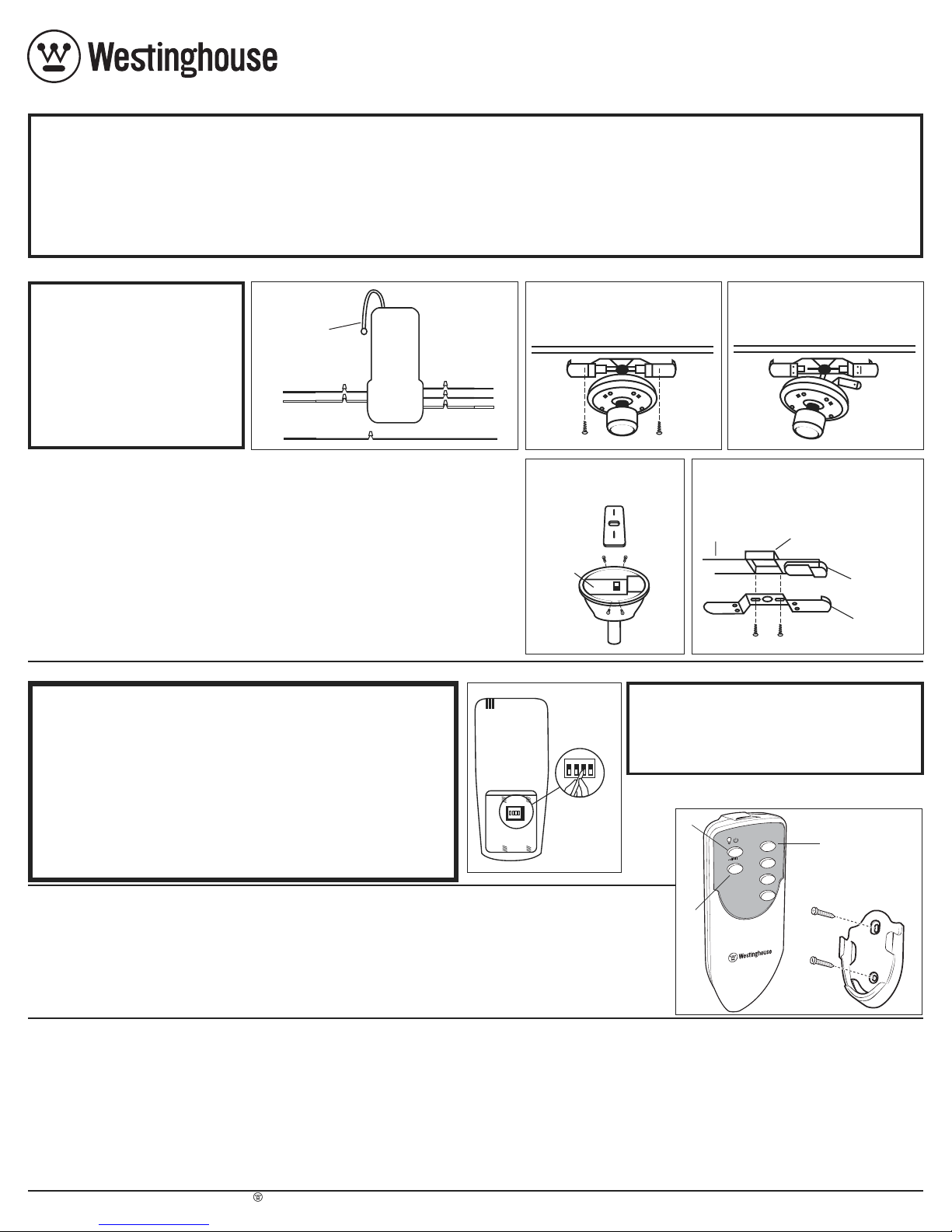
TRANSMISOR
1 2 3 4
1 2 3 4
FIGURA 6
NOTA: Todos los control remotos estan preajustados con un par de códigos
cuando se fabrican y están listos para usar. Si esta unidad causa interferencias
con otros aparatos, puede ajustar los interruptores de código en la parte
posterior del transmisor remoto (consulte la figura 6). Apague la alimentación
principal del ventilador y abra la cubierta posterior del transmisor remoto y
ajuste los interruptores de código. Una vez está ajustado el código, restablezca
la alimentación del ventilador y presione y mantenga presionado el botón "0"
en el transmisor durante 3 a 5 segundos. NOTA: Usted debe presionar el botón
"0" dentro de 60 segundos después de restablecer la alimentación del ventilador.
El ventilador funcionaría a velocidad media y luego se detendría y, mientras
tanto, la luz del ventilador parpadearía y se encendería, este proceso de
estudio se completaría y el control remoto estaría listo para su uso normal.
5. Operación para el control remoto:
1. Interruptor de encendido/apagado – presionar y soltar. El control remoto contro
la las velocidades del ventilador de la siguiente manera: 1 - alta; 2 – mediana;
3 - baja; 0 - apagado.
2. Conmutador de intensidad – al presionar continuamente el botón de luz, esta
última conmuta en un ciclo continuo de más claro a más oscuro.
3. Luz encendida/apagada –presionar y soltar el botón de luz.
Westinghouse Lighting
12401 McNulty Rd., Philadelphia, PA 19154-1029
Attn: Customer Service
Westinghouse Lighting, Philadelphia, PA 19154-1029, U.S.A. www.westinghouselighting , WESTINGHOUSE, and INNOVATION YOU CAN BE SURE OF are trademarks of Westinghouse Electric Corporation. Used under license by Westinghouse Lighting. All rights reserved. Made in China
3
2
1
0
1
2
3
ANTENNA
1.
SI EL VENTILADOR TIENE UNA VARILLA VERTICAL:
Retire el dosel
del ventilador de techo de la placa de montaje. Vaya al paso 3.
SI EL VENTILADOR ES DE MONTAJE AL RAS:
Retire el alojamiento
decorativo de la placa de montaje (vea la figura 2). Desconecte la pieza
de bracket
from mounting plate and allow to hang from one side
fijación de la placa de montaje y deje que cuelgue (vea la figura 3).
2.
Desconecte el cableado existente entre el ventilador de techo y el
suministro de corriente alterna en la caja de empalmes eléctricos.
ADVERTENCIAS:
•Siga las instrucciones al pie de la letra para evitar incendios, choques
eléctricos y heridas graves personales. Lea estas instrucciones y
consérvelas para futura referencia.
•Si faltan piezas o hay piezas dañadas, no instale este control remoto.
•
¡IMPORTANTE!
Antes de comprobar el funcionamiento de la unidad de
control remoto el ventilador y las aletas debería estar completamente
instalados.
AVISO:
1.
Este control remoto está diseñado para lámparas incandescentes, CFL y LED.
2.
Este control remoto está decuado para interiores y exteriores ubicación húmeda.
PRECAUCIONES DE SEGURIDAD:
2.
Este control tiene una capacidad nominal máxima de amperaje de motor
(únicamente el ventilador de techo) de1.25 con120 voltios, con un vatajetotal
(únicamente la lámpara incandescente) igual a 190 vatios máximo.
3. No lo utilice con ventiladores de techo de estado sólido.
4. El alojamiento decorativo (dosel) del techo debe ser de metal. El aloja-
miento de metal protege la unidad de control. NO LO UTILICE CON UN
ALOJAMIENTO QUE NO SEA DE METAL.
5. Para cambiar la velocidad del ventilador, utilice únicamente la unidad
de control remoto. No use la cadenilla de tiro para cambiar las veloci-
dades del ventilador después de la instalación.
6.
Cerciórese de que ningún cable sin aislación quede fuera de los conectores.
7.
Todo el cableado debe cumplir con los códigos eléctricos nacionales y
locales. Si piensa que no tiene suficientes conocimientos o experiencia en
cableado eléctrico, acuda a un electricista califocado para que le instale el
control del ventilador.
Todo trabajo eléctrico que no se describe en
este manual deberá ser realizado por un electricista califocado.
8. No use agua ni detergentes para limpiar la unidad de transmisión
remota. Solo limpialo con un paño suave y seco.
9. El empleo de este control podría causar incendio, choque eléctrico y
heridas graves personales cuando se utiliza para controlar algunos
ventiladores de techo. Use este control de ventilador únicamente con
ventiladores de techo de velocidad controlada por condensador.
B. INSTRUCCIONES PARA EL NUEVO SISTEMA DE CONTROL REMOTO DE VENTILADOR
ADVERTENCIA: ALTA TENSIÓN
Antes de conectar esta unidad de control:
•Desconecte el suministro eléctrico del circuito que utilizará.
•La tensión residencial puede causar heridas graves o la muerte.
•El cableado debe cumplir con los códigos eléctricos locales.
INTERRUPTORES
DE CÓDIGO
A. EXPLICACIÓN PARA HACER LAS CONEXIONES ELÉCTRICAS:
NOTA: Este control remoto funciona
únicamente con algunos modelos
de ventilador para
techo inclinado.
No use el control de velocidad del
ventilador en doseles cuyo montaje
no se describe en las figuras 4 ó 5.
Este control remoto no se puede
instalar en ventiladores con varilla
vertical en montaje al techo (cuando
no se utilice la varilla vertical).
3. Explicación para hacer las conexiones eléctricas:
•Asegúrese de que el cable VERDE del ventilador esté conectado al
cable de puesto a tierra de la casa (cobre pelado).
•Conecte el cable NEGRO de la unidad de control al cable NEGRO
de suministro eléctrico (CA vivo).
•Conecte el cable BLANCO de la unidad de control al cable
BLANCO de suministro eléctrico (CA neutro).
•Conecte el cable BLANCO de la unidad de control (MOTOR
neutro) al cable BLANCO del ventilador.
•Conecte el cable NEGROde la unidad de control (MOTOR
vivo) al cable NEGRO del ventilador.
•Conecte el cable AZUL de la unidad de control (PARA LA
LÁMPARA) al cable AZUL de la lámpara.
•
Introduzca los cables conectados dentro de la caja de embutir.
•Coloque el cable NEGRO de la unidad de control (ANTENA)
sobre la unidad de control.
•
SI EL VENTILADOR TIENE UNA VARILLA VERTICAL:
Coloque la
unidad de control en el dosel (vea la figura 4). Reinstale el dosel en
la
placa de montaje. Conecte el suministro eléctrico del circuito.
•
SI EL VENTILADOR ES DE MONTAJE AL TECH0:
Instale
la unidad de control en la placa de montaje o en el techo
con las cintas de amarre suministradas (vea la figura 5).
Reconecte la pieza de fijación a la placa de montaje (vea la
figura 2). Reinstale el alojamiento decorativo en la placa de
montaje. Conecte el suministro eléctrico del circuito.
NOTA: Si la unidad no cabe correctamente entre la
placa de montaje y el techo, monte la unidad en la
parte inferior de la placa de montaje.
NEGRO NEGRO
BLANCO BLANCO
AZUL
NEGRO NEGRO
BLANCO BLANCO
AZUL
UNIDAD DE
CONTROL
LÁMPARA
VENTILADOR
VENTILADOR
SUMINISTRO DE
CORRIENTE ALTERNA
SUMINISTRO DE
CORRIENTE ALTERNA
CABLE DE PUESTIO
A TIERRA COBRE PELAD VERDE VENTILADOR
FIGURA 1
FIGURA - 2
SÓLO VENTILADORES
DE MONTAJE AL TECHO
FIGURA- 3
SÓLO VENTILADORES
DE MONTAJE AL TECHO
UNIDAD DE
CONTROL
FIGURA - 4
SÓLO VENTILADORES
CON VARILLA VERTICAL
TECHO CAJA DE EMBUTI
PLACA DE MONTAJE
UNIDAD DE CONTROL
FIGURA- 5
SÓLO VENTILADORES
DE MONTAJE AL TECHO
GUÍA PARA SOLUCIONAR PROBLEMAS
PROBLEMA: EL CONTROL REMOTO NO FUNCIONA
Revise:
•¿Le está llegando electricidad a la unidad de control?
•¿Es correcto el cableado de la unidad de control?
•¿Están en la posición más alta los interruptores del ventilador y de la lámpara?
•¿Está buena la pila del control remoto? Si el indicador rojo se enciende cuando
oprime cualquiera de los botones, significa que la pila está buena.
PROBLEMA: POCO ALCANCE
Solución:
•
Si control remoto puede controlar la unidad a poca distancia pero no funciona
desde 9 a 12 metros (30-50 pies) de distancia, pruebe colocar el cable negro
de la antena encima del techo y fuera de la caja de embutir.
GARANTIA LIMITADA
El control remoto para ventiladores de techo de Westinghouse le ofrece
al propietario original una garantía limitada de un año, a partir de la fecha
de compra, contra materiales y mano de obra defectuosos. Todas las piezas
de repuesto están cubiertas por noventa días solamente. Esta garantía reem-
plaza a todas las otras garantías expresas o implícitas.
modificaciones al producto o intervenciones de terceros. Consulte el
manual del control remoto para su instalación correcta.
Si hace un reclamo de garantía dentro del primer año, simplemente envíe
el control remoto con una copia del recibo original de compra, con franqueo
prepago a Westinghouse Lighting Corporation, que a su discreción reparará o
reemplazará el control remoto o reintegrará el precio de compra.
Sírvase emba-
lar el producto adecuadamente para evitar daños durante el transporte.
Envíe el control remoto y dirija todas sus preguntas a:
Si tiene dudas acerca de la instalación de este artículo o de la cobertura
de la garantía, llame a nuestro Centro de atención al consumidor al
1-888-
417-6222
donde le ayudará un representante capacitado.
C. CONFIGURACIÓN DE LOS CONTROL REMOTOS (SOLAMENTE LA PRIMERA VEZ):
1. Esta unidad funciona con una sola baterias (pilas) de 9 voltios (incluida).
2.
Guarde la unidad de control en un lugar protegido contra el calor o humedad excesivos.
3.
Esta unidad de control remoto está equipada con 16 combinaciones de códigos.
Debido a la gran cantidad de combinaciones, es posible que otras unidades de
control remoto pudieran causar interferencia (por ejemplo, abrepuertas, alarmas
de auto, sistemas de seguridad, etc.). Si el ventilador o la lámpara se enciende o
se apaga sin que usted utilice el control remoto,
cambie los códigos en la unidad
de control del ventilador y en el transmisor remoto.
4. Si el ventilador de techo está equipado con controles de encendido/apagado
de cadenilla de tiro y velocidad variable, ponga el control de velocidad en la
velocidad MÁS ALTA y la lámpara en la posición de ENCENDIDO o MÁS
BRILLANTE antes de instalar el contro remote. De esta manera evitará las
velocidades erráticas y la posible avería de su ventilador de techo.
77878
Instrucciones para la instalación y modo de empleo del
control remoto de ventilador de techo con lámpara Westinghouse
ADVERTENCIA: DESCONECTE EL SUMINISTRO DE ENERGÍA QUITANDO EL FUSIBLE O APAGANDO EL CORTACIRCUITO ANTES DE INSTALACION
(PARTE POSTERIOR
DELCONTROL REMOTO)
Westinghouse reparará o reemplazará este control remoto en caso de
defectos ocasionados por materiales o mano de obra defectuosos. Esta
garantía no cubre los gastos de reparación, baterias (pilas), defectos
resultantes de accidentes,
averías ocasionadas por uso indebido o
alteraciones o por la instalación de cualquier accesorio que no sea
suministrado con el producto, instalación o mantenimiento incorrector, falla
de dispositivos de soporte no suministrados con los herrajes dee montaje
originales, exposición a cambios bruscos de temperature o humedad,
voltaje
incorrecto,
cambios de tensión, reparaciones no autorizadas o fallas
causadas por


