Whelen Engineering Company 295SL100 User manual

Page 1
Installation Guide:
Siren Model(s)
295SL100 (200W - 12V)
295SL101 (200W - 12V (w/Removable Mic)
295SL102 (200W - 24V)
©2006 Whelen Engineering Company Inc.
Form No.14045B (043008)
®
ENGINEERING COMPANY INC.
51 Winthrop Road
Chester, Connecticut 06412-0684
Phone: (860) 526-9504
Fax: (860) 526-4078
Internet: www.whelen.com
Sales e-mail: autosale@whelen.com
Canadian Sales e-mail: autocan@whelen.com
Customer Service e-mail: custserv@whelen.com
Automotive: Sirens/Switches
Safety First
This document provides all the necessary information to allow your Whelen product to be properly and safely installed.
Before beginning the installation and/or operation of your new product, the installation technician and operator must
read this manual completely. Important information is contained herein that could prevent serious injury or damage.
• Proper installation of this product requires the installer to have a good understanding of automotive electronics,
systems and procedures.
• If mounting this product requires drilling holes, the installer MUST be sure that no vehicle components or other
vital parts could be damaged by the drilling process. Check both sides of the mounting surface before drilling
begins. Also de-burr any holes and remove any metal shards or remnants. Install grommets into all wire
passage holes.
• If this manual states that this product may be mounted with suction cups, magnets, tape or Velcro®, clean the
mounting surface with a 50/50 mix of isopropyl alcohol and water and dry thoroughly.
• Do not install this product or route any wires in the deployment area of your air bag. Equipment mounted or
located in the air bag deployment area will damage or reduce the effectiveness of the air bag, or become a
projectile that could cause serious personal injury or death. Refer to your vehicle owner’s manual for the air bag
deployment area. The User/Installer assumes full responsibility to determine proper mounting location, based
on providing ultimate safety to all passengers inside the vehicle.
• For this product to operate at optimum efficiency, a good electrical connection to chassis ground must be
made. The recommended procedure requires the product ground wire to be connected directly to the NEGATIVE
(-) battery post.
• If this product uses a remote device to activate or control this product, make sure this control is located in an
area that allows both the vehicle and the control to be operated safely in any driving condition. DO NOT
ATTEMPT TO ACTIVATE OR CONTROL THIS DEVICE IN A HAZARDOUS DRIVING SITUATION.
• It is recommended that these instructions be stored in a safe place and
referred to when performing maintenance and/or reinstallation of this
product.
• FAILURE TO FOLLOW THESE SAFETY PRECAUTIONS AND
INSTRUCTIONS COULD RESULT IN DAMAGE TO THE PRODUCT OR
VEHICLE AND/OR SERIOUS INJURY TO YOU AND YOUR PASSENGERS!
For warranty information regarding this product, visit www.whelen.com/warranty
DANGER! Sirens produces extremely loud emergency warning tones! Exposure to these
tones without proper and adequate hearing protection, could cause ear damage and/or hearing
loss! The Occupational Safety & Health Administration (www.osha.gov) provides information
necessary to determine safe exposure times in Occupational Noise Exposure Section 1910.95.
Until you have determined the safe exposure times for your specific application, operators and
anyone else in the immediate vicinity should be required to wear an approved hearing protection
device. FAILURE TO FOLLOW THIS RECOMMENDATION COULD CAUSE HEARING LOSS!
CAUTION
Loud siren noise can cause
hearing damage and/or loss.
Refer to OSHA Section 1910.95 prior
to putting ANY siren into service!
Wear
Protection!
ACTIVATION OF THIS
SIREN MAY DAMAGE
UNPROTECTED EARS!

Page 2
“Acorn” Nut
Split Lock-Washer
Internal-tooth Lock-washer
Carriage Bolt
Mounting
The 295SL10 is designed to be mounted directly onto the dash or
other surface through the use of a bail strap mounting bracket.
The unit may also be mounted into your vehicle’s console (if so
equipped). Regardless of the style selected, be sure to
observe the air-bag warning on the cover of this manual.
Bail Strap Mount
1. Position the bail strap in the selected mounting location.
Using an awl or other suitable tool, scribe the surface where
the mounting holes are to be drilled.
Caution: As mounting this unit will require drilling, it is
absolutely necessary to make sure that no other
vehicle components could be damaged in the
process. Check both sides of the mounting
surface before starting. If damage is likely,
select a different mounting location.
2. Drill the mounting holes in the areas scribed in step 1. The
size of the drill bit should be determined by the size of the
mounting hardware used and thickness of the mounting
surface.
3. Secure the bail strap to the mounting location.
Note: There are 2 sets of holes on the bail strap for
positioning the unit at 2 different heights.
4. Secure the siren to the bail bracket using the provided
hardware as shown below.
5. Tighten the Acorn nut firmly.
Console Mount
Console manufacturers offer mounting kits that include all the
necessary hardware and brackets required to mount this unit into
their console. The console mount brackets are secured onto the
unit the same way the bail bracket is (except for the addition of
two flat washers that must be inserted between the siren and the
bracket). Please refer to the manual included with your console
for specific information on securing the siren/mounting bracket
assembly onto the console.
NOTE: Due to the lack of air flow within a console, prolonged
operation of this siren will require the console to be modified
to improve ventilation.
Congratulations on selecting the 295SL10 Series Siren! This series offers a unique and distinctive collection of features designed to
allow the user to customize the operation of this siren to suit their individual wants or needs.
• Power to drive two, 100-Watt
speakers.
• Scan-Lock™ Tone Programing
• Hands-Free operation.
• Radio Repeat.
• Auxiliary Input Control
• Horn ring Transfer
• Simulated mechanical siren tones.
• Harmonically-rich, composite
Airhorn tones.
• Title 13-compliant profiles.
•CompactSize
IMPORTANT AIR BAG WARNING! Do not install
this product or route any wires in the air bag
deployment zone of your vehicle. Equipment
mounted or located in air bag deployment zones will
damage or reduce the effectiveness of the air bag, or
become a projectile that could cause serious
personal injury or death. Refer to your vehicle
owners manual to learn the air bag deployment
zones for the vehicle. The User/Installer assumes full
responsibility to determine proper mounting
location, based on providing ultimate safety to all
passengers inside the vehicle.

Page 3
COLOR / GAGEPIN# FUNCTION
RED 14GA/
BLACK / 14GA
BLUE / 18GA
RED / 14GA
BLACK / 14GA
BLUE / 18GA
1
2
3
4
5
6
()
(-) GROUND
RADIO
(+) BATTERY
(-) GROUND
RADIO
+ BATTERY BROWN / 16GA
ORANGE / 16GA
VIOLET / 18GA
GRAY / 18GA
WHITE / 18GA
UNUSED
7
8
9
10
11
12
SPEAKER COM
+ SPEAKER
AUX. ENABLE
HORN
HORN/RING
COLOR / GAGE
PIN# FUNCTION
12 POSITION INPUT CONNECTOR
INPUT CONNECTOR
(REAR VIEW)
Scan-Lock™
Switch
3
2
1
6
5
4
9
8
7
12
11
10
Wiring:
Power & Ground Wires: RED: Power / BLACK: Ground
WARNING! All customer supplied wires that connect to the positive terminal of the battery must be sized to supply at
least 125% of the maximum operating current and FUSED at the battery to carry that load. DO NOT USE CIRCUIT
BREAKERS WITH THIS PRODUCT!
1. Splice the 2 RED (Power) wires together, then extend this single RED wire toward the vehicle battery. Splice the 2 BLACK
(Ground) wires together and extend this single BLACK wire toward the vehicle battery. To pass the RED and BLACK wires
through, you may have to drill a hole in the firewall. Be sure there are no components that could be damaged. Insert a grommet
in the hole to protect the wires.
2. Route the RED and BLACK wires along the factory harness towards the battery and install a fuse block (user supplied) on the
end of the RED wire (refer to the wiring schematic on page 4 for your model’s fuse value). NOTE: Remove the fuse from the
fuse block before connecting any wires to the battery.
3. Connect the fuse block wire to the POSITIVE (+) terminal on the battery. There must not be more than 2 feet of wire between
fuse block and battery. The wire between the fuse and the battery is “unprotected.” Do not allow it to contact with any wires.
4. Connect the BLACK wire to the factory chassis ground.
Speaker Wires: ORANGE & BROWN
1. Route the ORANGE and BROWN wires toward the vehicle siren speakers, along the factory wire harness and through the
firewall at the same point as the RED and BLACK wires.
2. Connect the ORANGE wire to the POSITIVE connection on speakers #1 & 2.
3. Connect the BROWN wire to the NEGATIVE connection on speakers #1 & 2.
Horn Relay Wires: WHITE & GREY
1. Route the WHITE and GREY wires along the factory wire harness and through the firewall at the same point as the RED and
BLACK wires.
2. Route the WHITE and GREY wires to your vehicle’s horn relay. If possible, follow the factory wire harness to this relay.
3. Locate the wire that connects the vehicle horn to the horn relay and
cut it.
4. Connect the WHITE wire to the wire coming from the horn relay.
5. Connect the GREY wire to the wire coming from the horn.
Radio Rebroadcast (optional): 2 BLUE wires
The two remaining BLUE wires are used to connect your two-way radio’s
external speaker for radio rebroadcast (an optional connection).
NOTE: If your remote speaker is amplified (has a power amp circuit in the
speaker), radio rebroadcast will not work and should not be enabled.
1. Locate the two wires that connect the external speaker to the two-
way radio, cut one of them and splice one of the BLUE wires into this
circuit.
2. Now cut the remaining speaker wire and splice the remaining BLUE
wire into this circuit.

Page 4
(+)
Battery
(-)
20 AMP FUSE (12V)
10 AMP FUSE (24V)
IINPUTCONNECTOR
CHASSIS
GROUND
TO 2-WAY
RADIO
SPEAKER
AUXILIARY
ENABLE
CONNECTION
(OPTIONAL)
BLUE
BLUE
BLACK
BLACK
100W
SPEAKER
BROWN
WHITE
GREY
RED
RED
UNUSED
3
6
9
5
2
7
11
10
4
1
12
VEHICLE
HORN
CUT WIRE HERE
HORN
RELAY +12V
TO HORN
BUTTON
295SL10* Siren
100W
SPEAKER
ORANGE8
WIRING DIAGRAM NOTE:
Do
use circuit breakers with this product!
All Fuses & Fuse Blocks are to
be supplied by the Customer. NOT
VIOLET
(TO PCDS-9 or EQUIV.)
T3
T2
T1
HF
MAN 2
MAN 1
RAD
MAN
RAD
T3
T2
T1
MIC
Connecting to a Remote Control Head:
(Optional)
This unit may be connected to an existing control head,
such as the Whelen PCDS-9 or equivalent. This is an
optional connection that enables the WAIL tone to be
activated through the use of a PCDS-9 button or switch.
If this connection is not chosen, cut the VIOLET wire and
cap it to prevent accidental grounding of the wire.
OPERATING THE CONTROLS:
PA VOLUME (MIC)
If your model uses a potentiometer, locate the
MIC adjustment port as shown. With the
vehicle in an enclosed area, turn the siren on
and speak into the microphone. While
speaking, insert the screwdriver and turn
clockwise to increase the volume. Continue to
increase the PA volume until audio feedback
occurs. Turn the screwdriver counter-clock
wise to eliminate feedback. For models with a
PA Volume knob, follow the same procedure
using the knob.
POWER
ON
POWER SWITCH
This switch has two positions: Down (Off) and Up
(On). When this switch is Off, the unit will not
function. When the switch is On, the siren is
functional and may be activated at the operator’s
discretion. This switch also activates control head
backlighting. NOTE: If the unit is connected to the
vehicle’s horn ring circuit, the vehicle horn is
disabled when the power switch is in the ON
position.
ROTARY SWITCH
The rotary knob controls the siren functions.
There are 7 positions that may be selected. Each
position and its function is outlined under “Rotary
Switch Operations.”
MAN BUTTON
The Manual button generates a variety of tones,
depending on what position the rotary knob is in.
For further explanation of this button’s function,
refer to “Rotary Switch Operations.”
RADIO REPEAT VOLUME (RAD)
Locate the Radio Repeat adjustment port as
shown. Set the volume level of the vehicle’s two-
way radio to its normal operating volume. Turn the
rotary knob to RAD to activate Radio Repeat.
Insert the screwdriver in the Radio Repeat
adjustment port and turn clockwise to increase
the volume.
RAD
T3
T2
T1
MIC
HF
MAN 2
MAN 1
RAD
MAN

Page 5
This section will outline the operation of the siren in the factory
default configuration. Refer to the Scan-Lock™ section on the
following page for information and procedures on how to
customize the operation of this siren.
RAD (Radio Repeat) - When the rotary knob is in the RAD
position, any signal that is received by the vehicle’s two-way
radio will be simultaneously broadcast over the vehicle’s
loudspeaker (the unit must be connected to the two-way radio as
outlined in this manual).
With the Rotary Switch in this Position:
• Pressing the MAN button will produce the AIRHORN
tone until the MAN switch is released.
• Activating the HORN RING input will produce the
AIRHORN tone until the MAN switch is released.
• Activating the AUX ENABLE input has no effect.
MAN 1 (Manual Siren #1) - When the rotary switch is in this
position the siren is in a standby state where no tones have been
activated, but is waiting for another action to be taken by the
operator.
With the Rotary Switch in this Position:
• Pressing the MAN button will produce the AIRHORN
tone until the MAN switch is released.
• Activating the HORN RING input will produce the
AIRHORN tone until the HORN RING input is released.
• Activating the AUX enable input will produce a
repeating WAIL tone.
MAN 2 (Manual Siren #2) - When the rotary switch is in this
position the siren is in a standby state. No tones will be activated
until another action is taken by the operator.
With the Rotary Switch in this Position:
• Pressing the MAN switch will produce a WAIL tone. This
tone will ramp up to peak frequency and stop when the
MAN switch is released.
• Activating the HORN RING input will produce a WAIL
tone. This tone will ramp up to peak frequency and stop
when the HORN RING input is released.
• Activating the AUX enable input will produce a
repeating WAIL tone.
HF (Hands-Free Operation) - When the rotary knob is in the HF
position, the siren functions are placed in a stand-by mode. Siren
tones are activated by a single “tap” on the MAN button or on the
vehicle’s steering wheel horn ring (if the vehicle’s horn has been
wired to the HORN RING input). The first tap produces a Wail
tone (a steady rise and fall tone). A second tap produces a Yelp
tone (a fast rise and fall tone). A third tap produces a Piercer™
tone (an extremely fast rise and fall tone). The next tap returns
the siren to a Wail tone and the cycle repeats itself. Two quick
successive taps will stop the siren.
With the Rotary Switch in this Position:
• Pressing the MAN button will produce the HF cycle as
described above.
• Activating the HORN RING input will produce the HF
cycle as described above.
• Activating the AUX ENABLE input will start the HF
cycle. Releasing the AUX ENABLE will stop the cycle.
T1 (Tone #1) - When the rotary knob is in the T1 position, a
steady, rise and fall tone (WAIL) is produced.
With the Rotary Switch in this Position:
• Pressing the MAN button will change the siren tone to a
Yelp pattern (a fast rise and fall tone). Pressing the MAN
button a second time returns it back to Wail.
• Activating the HORN RING input will change the siren
tone to Yelp. Activating the HORN RING input again to
return to a Wail tone.
• Activating the AUX ENABLE input has no effect.
T2 (Tone #2) - When the rotary knob is in the T2 position, a fast,
rise and fall tone (YELP) is produced.
With the Rotary Switch in this Position:
• Pressing the MAN button will produce the Piercer™
tone. Pressing the MAN switch a second time returns it
back to Yelp.
• Activating the HORN RING input will produce the
Airhorn tone until the HORN RING input is released.
• Activating the AUX ENABLE input has no effect.
T3 (Tone #3) - When the rotary knob is in the T3 position, an
extremely fast, rise and fall tone is produced.
With the Rotary Switch in this Position:
• Pressing the MAN button will result in the AIRHORN
tone until the MAN button is released.
• Pressing the HORN RING input will result in the
AIRHORN tone until the HORN RING input is released.
• Activating the AUX ENABLE will have no effect.
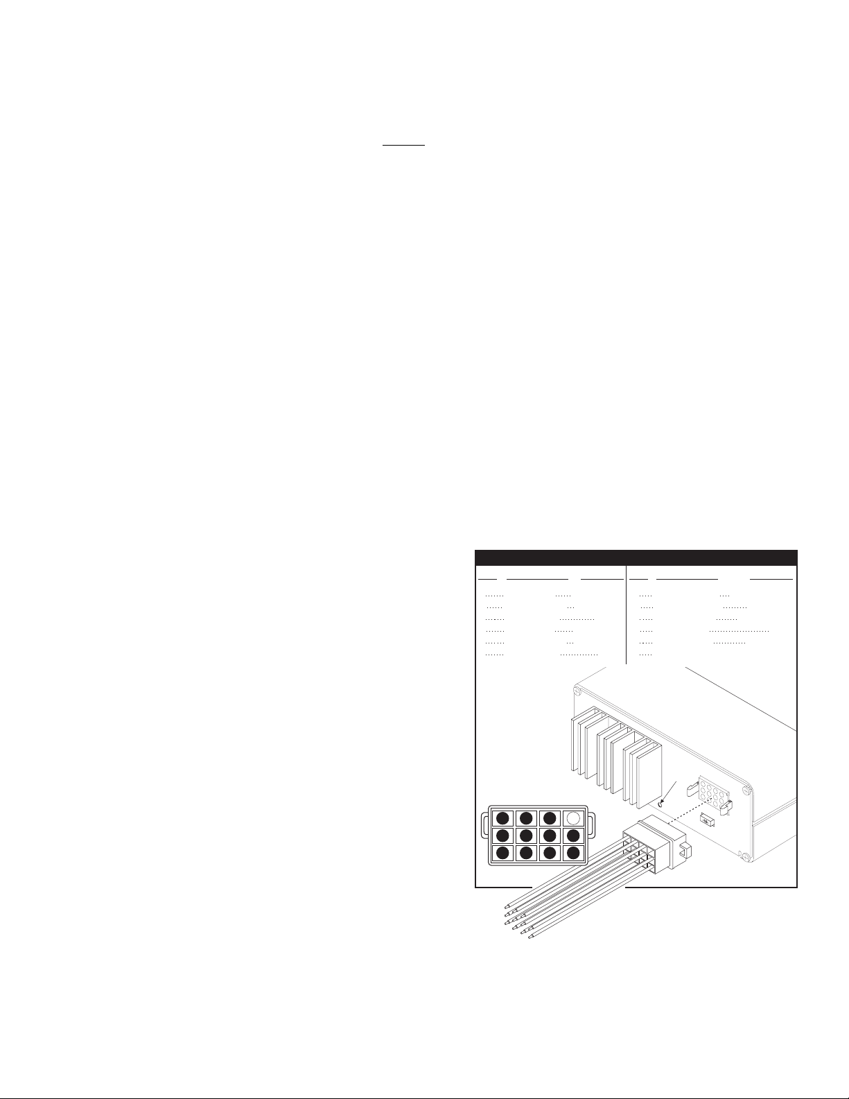
12-Volt Models 24-Volt Models
INPUT VOLTAGE . . . . . . . . . . . . . . . . . . . . 12 VDC ±20% 24 VDC ±20%
INPUT CURRENT . . . . . . . . . . . . . . . . . . . 16 AMPS (TYP.) 8 AMPS (TYP.)
INPUT FUSE . . . . . . . . . . . . . . . . . . . . . . . . . . . . 20 AMPS 10 AMPS
SPEAKER IMPEDANCE. . . . . . . . . . . . . . . 11 OHMS MIN. 11OHMS MIN.
OPERATING TEMPERATURE . . . . . . . -30° C. TO +80° C. -30° C. TO +80° C.
STORAGE TEMPERATURE. . . . . . . . .-40° C. TO +70° C. -40° C. TO +70° C.
HUMIDITY . . . . . . . . . . . . . . . . . . . 99% (Non-Condensing) 99% (Non-Condensing)
Rotary Switch Operations
CAUTION
Loud siren noise can cause
hearing damage and/or loss.
Refer to OSHA Section 1910.95 prior
to putting ANY siren into service!
Wear
Protection!
ACTIVATION OF THIS
SIREN MAY DAMAGE
UNPROTECTED EARS!

Page 6
With Scan-Lock the tonal operation of the siren can be
customized to fit the users needs. A momentary switch, accessed
through a small hole on the back of the siren, is used to change
the default siren tones as outlined below. A non-conductive tool
(such as the tip of a pen) should be used to actuate this switch.
To change the primary tone for rotary switch positions T1, T2,
and T3: Put the rotary switch in the position that you wish to
change. Press and release the Scan-Lock switch. Each time the
Scan-Lock switch is pressed and released, the next available tone
will be broadcast (see “Tone List For Rotary Switch Positions T1,
T2 & T3”). When the desired tone is generated, it will
automatically be saved for that rotary switch position.
To change the override tone for rotary switch positions T1,
T2. and T3: Put the rotary switch in the position that you wish to
change. Press and hold the MAN button on the front panel on the
siren. Press and release the Scan-Lock™ switch. Each time the
Scan-Lock™ switch is pressed and released, the next available
tone will be broadcast (see “Override Tone List For Rotary Switch
Positions T1, T2 & T3”). When the desired tone is present, it will
automatically be saved as the override tone for that rotary switch
position. Release the MAN button.
To change one of the tones in the hands free cycle as
described in the “Rotary Switch Operations” section of this
manual: Put the rotary switch in the HF position. Using the MAN
button on the front panel on the siren, advance to the tone that
you wish to change. Press and release the Scan-Lock switch.
Each time the Scan-Lock switch is pressed and released, the next
available tone will be broadcast (see “Tone List For Hands-Free
Operation”). When the desired tone is generated, it will
automatically be saved for that Hands-free cycle position.
To change the tone for rotary switch positions MAN1 or
MAN2: Put the rotary switch in the position that you wish to
change. Press and hold the MAN button on the front panel on the
siren. Press and release the Scan-Lock switch. Each time the
Scan-Lock switch is pressed and released, the next available tone
will be broadcast (see “Tone List For MAN1 & MAN2 Operation”).
When the desired tone is generated, it will automatically be saved
for that rotary switch position. Release the MAN button.
To change the override tone for rotary switch position RAD:
Put the rotary switch in the RAD position. Press and hold the MAN
button on the front panel on the siren. Press and release the
Scan-Lock switch. Each time the Scan-Lock switch is pressed and
released, the next available tone will be broadcast (see “Override
Tone List For RADIO Rotary Switch Position”). When the desired
tone is generated, it will automatically be saved for that rotary
switch position. Release the MAN button.
Tone List For Rotary Switch Positions T1, T2 & T3:
TONE OFF
WAIL*
YELP*
PIERCER™
Y-249*
HI/LOW
SIMULATED MECHANICAL
PULSED AIRHORN
AIRHORN HI/LOW
WOOP
WARBLE
Override Tone List For Rotary Switch Positions T1, T2 & T3:
TONE OFF
WAIL
YELP
PIERCER
Y-249
HI/LOW
SIMULATED MECHANICAL
PULSED AIRHORN
AIRHORN HI/LOW
WOOP
WARBLE
AIRHORN
LOW FREQ. AIRHORN
Tone List For Hands Free Operation:
WAIL
YELP
PIERCER™
Y-249
HI/LOW
SIMULATED MECHANICAL
PULSED AIRHORN
AIRHORN HI/LOW
WOOP
WARBLE
Tone List For MAN1 & MAN2 Operation:
TONE OFF
MANUAL SIMULATED MECHANICAL COAST-TO-STOP
MANUAL SIMULATED MECHANICAL STOP
MANUAL WAIL COAST-TO-STOP
MANUAL WAIL STOP
AIRHORN
LOW FREQ. AIRHORN
Override Tone List For Rotary Switch Position Radio:
TONE OFF
AIRHORN COMMAND CODE
AIRHORN LOW COMMAND CODE
Scan-Lock™ Programing Procedures
To Restore the Factory Default Configuration - Place the rotary switch into a Stand-by
position (MAN1, MAN2, HF) and turn the unit OFF. While holding the Scan-Lock switch down,
turn the unit ON. The factory default configuration is now restored.
* WAIL, YELP & Y-249 are California Title-13 Compliant
Siren Tones.

Page 7
Current Draw (AMPS)
Wire Gauge
Calculation Chart
All Distances Shown Are In FeetINS. = Insufficient
5
22
6
3
INS.
INS. INS.
INS.
INS. INS.
INS.
INS.
INS. INS.
INS. INS.
INS. INS.
INS. INS.
INS. INS.
INS. INS.
INS. INS. INS.
INS. INS. INS.
INS. INS. INS.
INS. INS. INS.
INS. INS. INS.
INS. INS. INS.
INS.
INS.
INS.
INS.
INS.
INS.
INS.
INS.
INS.
INS.
INS.
INS.
INS.
INS.
INS.
INS.
INS.
INS.
INS.
INS.
INS.
INS.
INS.
INS.
INS.
INS.
INS.
INS.
INS.
INS.
20
9.5
5
3
18
15
7.5
5
4
3
16
24.5
12
8
6
5
4
3.5
3
14
39
19.5
13
9.5
8
6.5
5.5
5
4.5
4
3.5
3
3
3
12
62
31
20.5
15.5
12.5
10.5
9
7.5
7
6
5.5
5
5
4.5
4
4
3.5
3.5
3.5
3
10
98
49
32.5
24.5
19.5
16.5
14
12.5
11
10
9
8
7.5
7
6.5
6
6
5.5
5
5
8
156
78
52
39
31
26
22.5
19.5
17.5
15.5
14
13
12
11
10.5
10
9
8.5
8
8
6
248
124
82.5
62
49.5
41.5
35.5
31
27.5
25
22.5
20.5
19
17.5
16.5
15.5
14.5
14
13
12.5
4
395
197
131
98.5
79
66
56.5
49.5
44
39.5
36
33
30.5
28
26.5
24.5
23
22
21
19.5
2
629
314
209
157
125
104
89.5
78.5
69.5
63
57
52.5
48.5
45
42
39
37
35
33
31.5
10
15
20
25
30
35
40
45
50
55
60
65
70
75
80
85
90
95
100
Wire Gauge (AWG)
To use this chart...
1. Determine the amount of current being drawn through the wire. Locate this number in the vertical left-hand
column. If the current value is between adjacent values, use the higher number.
2. Follow this row until the length of the installed wire is shown. If the exact length is between adjacent values, use
the higher number. Follow this column upwards to find the recommended size (gage) for this wire.
In the example shown below, the size for a wire with an installed length of 36 feet, through which 22 amps of current
will be drawn, must be determined.
A row for 22 amps is not shown, so the row for 25 amps will be used. Follow this row to the right. A column for 36 feet
is not shown, so the column for 49.5 feet will be used. Following this column to the top will show that the size of this
wire must be at least 6 gage.
This manual suits for next models
3
Table of contents
Popular Marine Equipment manuals by other brands

Balmar
Balmar Max Charge MC-612 Installation and operator's manual

GUIDANCE MARINE
GUIDANCE MARINE RadaScan View Installer's guide

Teknim
Teknim TFS-1191 installation manual

Vingtor Stentofon
Vingtor Stentofon MASTER CLOCK SYSTEM 70000 Technical user's manual

Pfannenberg
Pfannenberg DS5-SIL instruction manual

Kongsberg
Kongsberg Simrad CS90 Reference manual