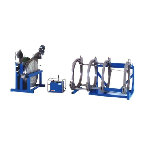
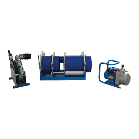
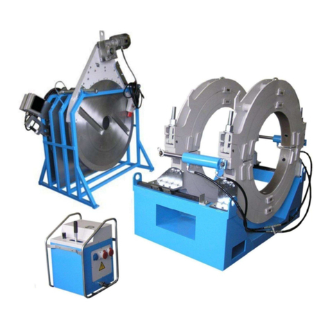
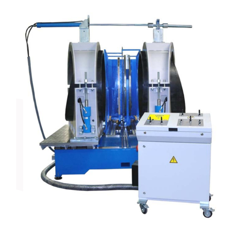
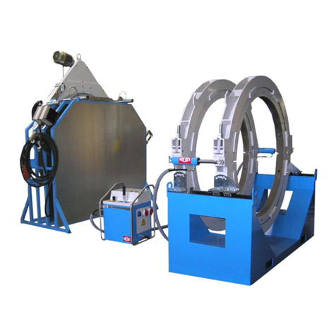
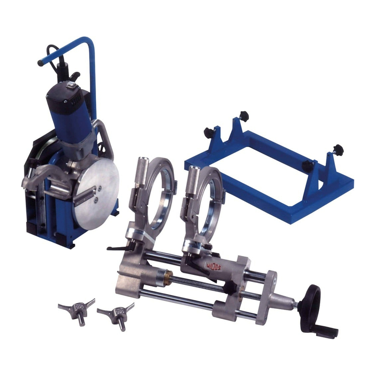
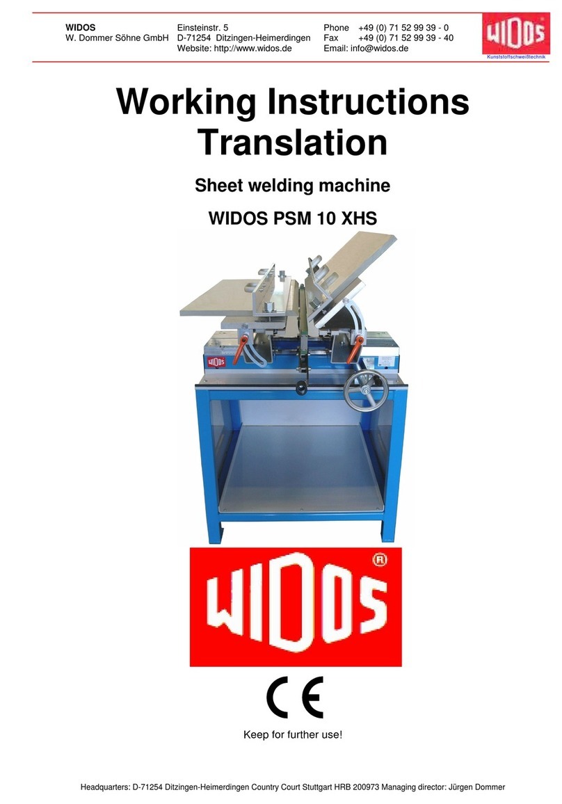
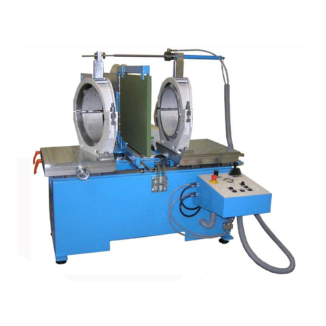
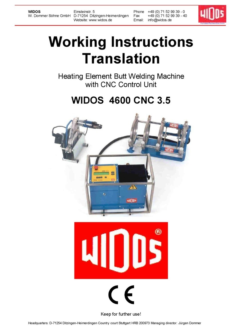
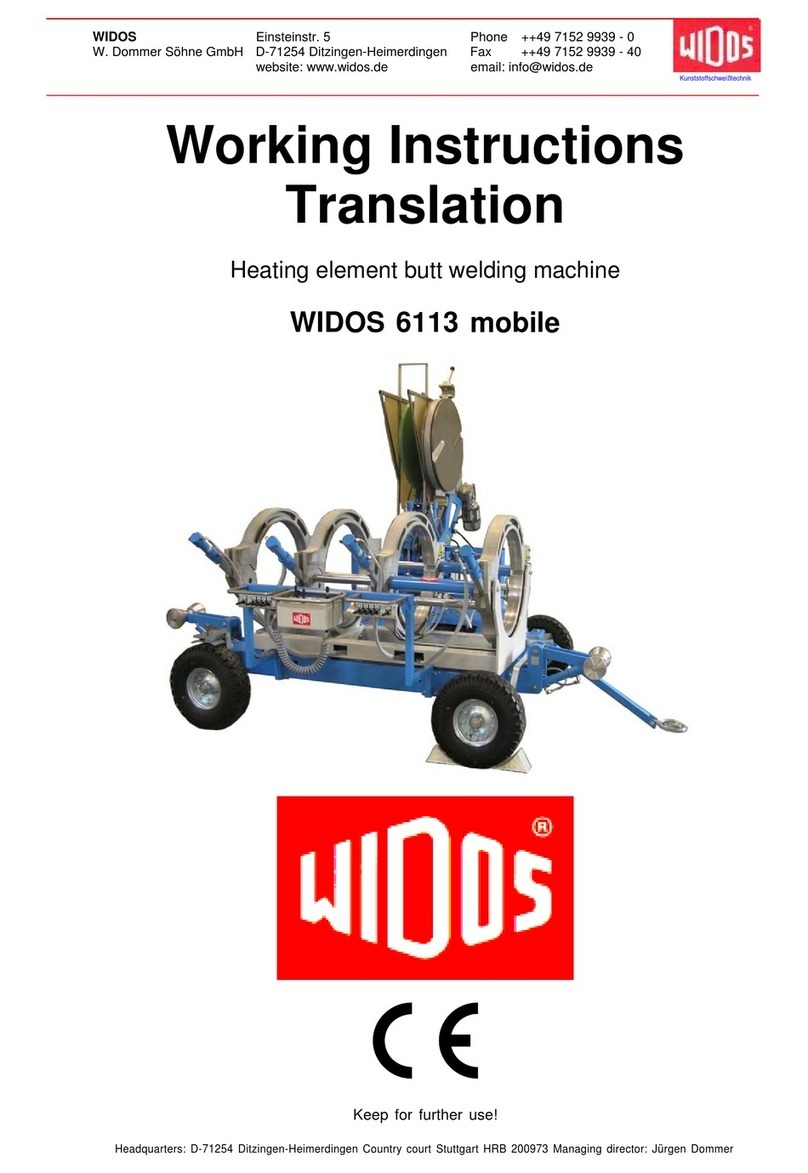
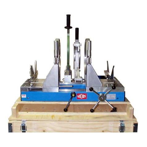
widos 4900 User manual

Ku nst sto ffsch weißtec hni k
WIDOS Einsteinstr. 5 Phone +49 7152 9939 - 0
W. Do er Söhne G bH D-71254 Ditzingen-Hei erdingen Fax +49 7152 9939 - 40
info @ widos.de
www.widos.de
Headquarters: D-71254 Ditzingen-Hei erdingen County court Stuttgart HRB 200973 Managing director: Jürgen Do er
Working Instructions
Translation
Heating element butt welding machine
WIDOS 4900
Keep for further use!

Ku nst sto ffschwei ßtechn i k
Identification of product
02.11.11 Working instructions WIDOS 4900 Page 2 of 46
Version: Ditch achine
Type: WIDOS 4900
Serial nu ber / year of construction: see type lable
Customer's entries
Inventory- No.:
Place of working:
ddress of manufacturer
WIDOS
W. Do er Söhne G bH
Einsteinstraße 5
D-71254 Ditzingen-Hei erdingen
Phone: +49 (0) 71 52 / 99 39 – 0
Fax: +49 (0) 71 52 / 99 39 – 40
Order of spare parts and sales service:
Directly at the anufacturer or at the subsidiary co panies:
WIDOS
WIDOS G bH W. Do er AG
An der Wiesen ühle 15 St. Gallerstr. 93
D-09224 Grüna / Sachsen CH-9201 Gossau
Phone: +49 (0) 3 71 / 8 15 73 - 0 Phone: +41 (0) 71 / 388 89 79
Fax: +49 (0) 3 71 / 8 15 73 - 20 Fax: +41 (0) 71 / 388 89 73

Ku nst sto ffschwei ßtechn i k
Introduction
02.11.11 Working instructions WIDOS 4900 Page 3 of 46
Purpose of the document
These working instructions give you infor ation about all i portant questions which refer to the
construction and the safe working of your achine.
Just as we are, you are obliged to engage in these working instructions, as well.
Not only to run your achine econo ically but also to avoid da ages and injuries.
Should questions arise, contact our advisers in the factory or in our subsidiary co panies.
We will help you with pleasure.
According to our interest to continuously i prove our products and working instructions, we
kindly ask you to infor us about proble s and defects which occur in exercise.
Thank you.
Structure of the working instructions
This anual is arranged in chapters, which belong to the different using phases of the achine.
Therefore the searched infor ation can be easily found.
WIDOS 02.11.2011
W. Do er Söhne G bH
Einsteinstraße 5
D-71254 Ditzingen-Hei erdingen
All rights reserved
Reprinting only allowed with per ission of the corporation.
Any changes prior to technical innovations.

Ku nst sto ffschwei ßtechn i k
Contents
02.11.11 Working instructions WIDOS 4900 Page 4 of 46
1.
DESCRIPTION OF PRODUCT ............................................................................................. 6
1.1.
pplication and prescribed use ......................................................................................6
1.2.
Machine overview ............................................................................................................6
1.3.
Safety measures ..............................................................................................................7
1.4.
Conformity........................................................................................................................7
1.5.
Designation of product....................................................................................................7
1.5.1
Technical Data ...............................................................................................................7
1.5.1.1
WIDOS 4900 General data..................................................................................7
1.5.1.2
Planer....................................................................................................................8
1.5.1.3
Heating ele ent.....................................................................................................8
1.5.1.4
Hydraulic aggregate...............................................................................................9
1.5.1.5
Basic fra e ...........................................................................................................9
1.6.
Equipment and accessories: ..........................................................................................9
2.
S FETY RULES................................................................................................................... 10
2.1.
Explanation of the different symbols............................................................................10
2.2.
Obligations of the owner................................................................................................11
2.3.
Obligations of the worker ..............................................................................................11
2.4.
Organizational measures...............................................................................................11
2.5.
Informal security measures...........................................................................................11
2.6.
Instruction of the staff ...................................................................................................11
2.7.
Dangers while handling the machine............................................................................12
2.8.
Maintenance and inspection, repair..............................................................................12
2.9.
Dangers caused by electric energy ..............................................................................12
2.10.
Dangers caused by the hydraulics ...............................................................................12
2.11.
Special dangers .............................................................................................................13
2.11.1
Danger of catching clothes by the planer..................................................................13
2.11.2
Danger of noise .......................................................................................................13
2.11.3
Danger of burning at heating ele ent, heat protective box and welding area...........13
2.11.4
Danger of stu bling over hydraulic and electric wires ..............................................13
2.11.5
Danger of squeezing by cla ping tool and guideways ..............................................14
2.12.
Structural modifications on the machine .....................................................................14
2.13.
Cleaning the machine ....................................................................................................14
2.14.
Guarantee and liability ...................................................................................................14
3.
FUNCTION L DESCRIPTION............................................................................................ 15
4.
OPER TING ND INDIC TING ELEMENTS .................................................................. 16
4.1.
Elements on the hydraulic aggregate...........................................................................16
4.2.
Elements at the heating element ..................................................................................17
4.3.
Separating device for heating element.........................................................................17
Ku nst sto ffschwei ßtechn i k
Contents
02.11.11 Working instructions WIDOS 4900 Page 5 of 46
4.4.
Elements at the planer...................................................................................................18
5.
ST RTING ND OPER TING........................................................................................... 19
5.1.
Starting ...........................................................................................................................19
5.1.1
Replacing the reduction inserts ....................................................................................20
5.1.2
Using s all and large reduction inserts.........................................................................20
5.2.
Welding process ............................................................................................................21
6.
WELDING LOGS ND T BLES........................................................................................ 23
7.
M INTEN NCE ND REP IR .......................................................................................... 28
7.1.
Clamping elements ........................................................................................................28
7.2.
Planer..............................................................................................................................28
7.3.
Storing ............................................................................................................................28
7.4.
Used hydraulic oil...........................................................................................................28
7.5.
Checking the hydraulic oil level ....................................................................................28
7.6.
Venting the hydraulic cylinders.....................................................................................29
8.
TR NSPORT ....................................................................................................................... 30
9.
ELECTRIC ND HYDR ULIK DI GR MS...................................................................... 31
10.
SP RE P RTS LIST ........................................................................................................... 35
10.1.
Basic machine................................................................................................................35
10.2.
Planer..............................................................................................................................37
10.3.
Hydraulic aggregate.......................................................................................................39
10.4.
Heating element .............................................................................................................42
10.5.
Reception box ................................................................................................................44
11.
DECL R TION OF CONFORMITY .................................................................................. 46

Ku nst sto ffschwei ßtechn i k
WIDOS Einsteinstr. 5 Phone +49 7152 9939 - 0
W. Do er Söhne G bH D-71254 Ditzingen-Hei erdingen Fax +49 7152 9939 - 40
info @ widos.de
www.widos.de
02.11.11 Working instructions WIDOS 4900 Page 6 of 46
1. Description of product
This chapter gives i portant basic infor ation about the product and its prescribed use.
All technical details of the achine are put together as a general arrange ent.
1.1. pplication and prescribed use
The WIDOS 4900 is ade for heating ele ent butt welding of pipes and fittings with a dia eter
range of Ø = 90 - 315 .
It is a building site achine and is designed especially for the use on site as well as in the
workshop.
For this reason, the fra e is kept s all such that it can also be used in constrained positions
(e.g. building ditches).
All use going beyond is not prescribed.
The anufacturer is not responsible for da ages caused by isuse.
The risk is held only by the user.
Prescribed use also eans:
taking notice of all re arks in this anual
perfor ing of repair works.
1.2. Machine overview
1
Planer
2
Heating ele ent
3
Protective box
4 Hydraulic aggregate
5
Basic achine with cla ping tools
1
2
3
4
5

Ku nst sto ffschwei ßtechn i k
Description of product Chapter 1
02.11.11 Working instructions WIDOS 4900 Page 7 of 46
1.3. Safety measures
In case of wrong use, wrong operation or wrong aintenance the achine itself or products
being in the surrounding can be da aged or destroyed.
Persons being in the endangered area ay be injured.
Therefore these working instructions have to be thouroughly read and the corresponding safety
advices ust be necessary adhered to.
1.4. Conformity
The achine corresponds in its construction to the valid reco endations of the European
Co unity as well as to the European standard specifications.
The develop ent, anufacturing and ounting of the achine were ade very carefully.
1.5. Designation of product
The product is designated by two signs at the fra e.
The type-labels are fixed on the control unit and on the basic achine.
They contain the type of the achine, the serial nu ber, and the year of construction.
1.5.1 Technical Data
1.5.1.1 WIDOS 4900 General data
Material: PP, PE 80, PVDF, PE 100
Pipe dia eter range: outside-∅ = 90 – 315
Transport box (l x w x h) / weight:
Partition boxes for reduction inserts:
4- partition:
7- partition:
9- partition:
approx. 1230 x 980 x 670 / approx. 67 kg
appr. 680 x 410 x 310 weight: appr. 10 kg
appr. 1160 x 410 x 310 weight: appr. 16 kg
appr. 1470 x 410 x 310 weight: appr. 21 kg
Total weight (without packing): approx. 130 kg
Protection: 16 A
Wire cross section: 1,5 ²
E issions - Noises exceeding 80 dB (A) ay occur; during
planing it is obligatory to wear ear protection!
- when using the na ed pipe aterials and when
welding below 260° C no toxicant da p arises.

Ku nst sto ffschwei ßtechn i k
Description of product Chapter 1
02.11.11 Working instructions WIDOS 4900 Page 8 of 46
Environ ent: - keep the workshop clean (especially the welding
area ust be clean)
- If secured by an appropriate easure ent that
allowed conditions for welding are indicated, it is
possible to work in any outside te perature
condition as far as the welder is not constrained in
its anual skill.
- avoid hu idity, if necessary put up a tent
- avoid strong sun bea s
- if it is windy shut the pipe endings.
1.5.1.2 Planer
Motor: onophase-alternating current- otor
Power: 1,05 kW
Voltage: 230 V (± 10 %)
Current: 4,5 A
Frequency: 50 Hz (± 10 %)
RPM n2 of planer approx. 60 revs/ in.
Ele ents: Switch on / off with fixing device
Connecting cable and plug with earthing contact
Weight: approx. 14 kg
1.5.1.3 Heating ele ent
Power: 2,1 kW
Voltage: 230 V (± 10 %)
Current: 10 A (± 10 %)
Frequency: 50 Hz
Outside-∅: 350
Surface: Antistick-coated
Ele ents: Electronic te perature control
Control la ps, switch on / off
Connecting cable and plug with earthing contact
Weight: approx. 13 kg

Ku nst sto ffschwei ßtechn i k
Description of product Chapter 1
02.11.11 Working instructions WIDOS 4900 Page 9 of 46
1.5.1.4 Hydraulic aggregate
Power: 0,3 kW
Voltage: 230 V (± 10 %)
Current: 2,7 A
Frequency: 50 Hz
Hydraulic oil tank: approx. 1 l
Electro otor and pu p:
RPM: 1380 (revs/ in.)
ax. pressure of pu p: approx. 120 bar
Working pressure: 100 bar
Volu e velocity: 1,9 l/ in
Weight : approx. 23 kg
1.5.1.5 Basic fra e
Di ensions (l x w x h): 800 x 460 x 500
Reduction insert : Di ensions can be selected
Material fra e: Machine steel
Material reduction inserts: Alu iniu
Weight: approx. 60 kg
Cylinder-∅: 40
Piston rod-∅: 35
Length of stroke of cylinder: 175
ax. force: (F=P*A) 5900 N (at 100 bar)
Velocity of piston rod: 5,4 c /s
Stock nu bers for co ponent parts see spare parts list
1.6. Equipment and accessories:
The following accessories are part of the first delivery:
1 Tool bag for 10 parts
1 Socket wrench size 27
1 each Allan key size 3; 6; 7; 8
1 each Allan key with T-grip size 5; 7
optional Reduction inserts, roller brackets for the pipes
1 Torx-screw driverT10

Ku nst sto ffschwei ßtechn i k
WIDOS Einsteinstr. 5 Phone +49 7152 9939 - 0
W. Do er Söhne G bH D-71254 Ditzingen-Hei erdingen Fax +49 7152 9939 - 40
info @ widos.de
www.widos.de
02.11.11 Working instructions WIDOS 4900 Page 10 of 46
2. Safety rules
The base for the safe handling and the fault-free operation of this achine is the knowledge of
the basic safety indications and rules.
The security notices of this chapter represent the general part.
Particular infor ation is listed directly before the corresponding actions.
These working instructions provide you with the ost i portant infor ation to run the
achine safely.
The safety infor ation ust be read by all persons who work on the achine.
2.1. Explanation of the different symbols
The working instructions contain the following signs for certain situations:
This sy bol eans a possibly danger for the life and the health of persons.
• The disrespect of these indications ay have heavy consequences for the
health.
This sy bol eans a possible dangerous situation.
• The disrespect of these indications ay cause slight injuries or da ages on
goods.
This sy bol eans a possible dangerous situation due to hot surfaces.
• The disrespect of these indications ay conduct to heavy burns, respectively to
self-ignition or even fire.
This sy bol eans a possible dangerous situation by oving parts of the achine
The disrespect of these indications ay cause heavy crushings of parts of
the body resp. da ages of parts of the achine.
This sy bol eans a possible risk of injury by noises exceeding 80 dB (A).
• Ear protection is obligatory
This sy bol gives i portant indications for the proper use of the achine.
• The disrespect of these indications ay conduct to alfunctions and da ages
on the achine or on goods in the surrounding.
Under this sy bol you get user tips and particularly useful infor ation.
• It is a help for using all the functions on your achine in an opti al way and
helps you to ake the job easier.
The regulations for the prevention of accidents are valid (UVV).

Ku nst sto ffschwei ßtechn i k
Safety rules Chapter 2
02.11.11 Working instructions WIDOS 4900 Page 11 of 46
2.2. Obligations of the owner
The owner is obliged only to let persons work on the achine, who
• know about basic safety and accident prevention rules and are instructed in the handling of
the achine.
• The workers also ust have read and understood the safety chapter of this anual and
certify this with their signature.
The safety-conscious working of the staff should be checked in regular intervals.
2.3. Obligations of the worker
All persons who are to work at the achine are obliged before working:
• To take care of the basic safety and accident protection rules.
• To have read and understood the safety chapter and the warnings in this anual and to
certify this with their signature.
• To infor the selves about the functions of the achine before using it.
2.4. Organizational measures
• All equip ent required for personal safety is to be provided by the owner.
• All available safety equip ent is to be inspected regularly.
2.5. Informal security measures
• The anual has to be per anently kept at the place of use of the achine. It is to be at the
operator‘s disposal at any ti e and without effort.
• As a supple ent to the working instructions, the generally valid and also the local regulations
for the prevention of accidents and the protection of the environ ent are to be provided and
adhered to.
• All security and danger notices on the achine have to be kept in a readable state.
• Every ti e the achine changes hands or is being rented to third persons, the working
instructions are to be sent along with and their i portance is to be e phasized.
2.6. Instruction of the staff
• Only skilled and instructed persons are allowed to work at the achine.
• The responsibilities of the staff are to be deter ined clearly concerning transport, ounting
and dis ounting, starting, adjusting and tooling, operating, aintenance and inspection,
repairs.
• Workers who are to be trained are only allowed to work at the achine under control of an
experienced worker.

Ku nst sto ffschwei ßtechn i k
Safety rules Chapter 2
02.11.11 Working instructions WIDOS 4900 Page 12 of 46
2.7. Dangers while handling the machine
The achine WIDOS 4900 is constructed according to the actual technical standard and the
acknowledged technical safety rules.
However, dangers for the operator or other persons standing nearby ay occur.
Also da ages to the achine itself or to other things are possible.
The achine ust only be used:
• according to the prescription
• in safety technical i peccable status
Disturbances, which may affect the safety of the machine must be eliminated immediately.
2.8. Maintenance and inspection, repair
All aintenance and repair works have to be basically perfor ed with the achine
in off position.
During this the achine has to be secured against unauthorized switching on.
Prescribed aintenance and inspection works should be perfor ed in ti e.
The DVS gives the advice of inspection works after 1 year.
For achines with a specially high usage percentage the testing cycle should be
shortened.
The works should be perfor ed at the WIDOS G bH co pany or by
an authorized partner.
2.9. Dangers caused by electric energy
Only skilled workers are allowed to work at electrical appliances!
The electrical equip ent of the achine has to be checked regularly.
• Loose connections and da aged cables have to be replaced i ediately.
• If works at alive parts are necessary, a second person has to assist who can disconnect the
achine fro the ains if necessary.
• All electric tools (heating ele ent, planer and aggregate) have to be protected fro rain and
dropping water (if need be use a welding tent).
• According to VDE 0100, the use on construction sites is only allowed with a power distributor
with a FI-safety switch.
2.10. Dangers caused by the hydraulics
Syste parts and pressure hoses should be ade pressureless before beginning
of any repair works. Even if the achine is switched off, pressure ay be in the
hydraulic accu ulator!
There is a danger of injuring the eyes by hydraulic oil squirting out.
• Da aged hydraulic hoses have to be i ediately replaced.
• Make a visual inspection of the hydraulic hoses before each work beginning.
• The hydraulic oil is inedible!

Ku nst sto ffschwei ßtechn i k
Safety rules Chapter 2
02.11.11 Working instructions WIDOS 4900 Page 13 of 46
2.11. Special dangers
2.11.1 Danger of catching clothes by the planer
There is the danger of cutting yourself or even breaking bones!
• Wear only tight clothes.
• Do not wear rings or jewellery during work.
• If necessary wear a hair-net.
• Always put the planer back into the reception case after and before each use.
• Only transport the planer at the handle.
• Do not touch the planer surfaces.
• Switch on the planer only for use. Otherwise the planer will start every ti e when the security
icroswitch is pressed.
2.11.2 Danger of noise
Noises exceeding 80 dB (A) ay occur; during planing it is obligatory to wear ear
protection!
2.11.3 Danger of burning at heating element, heat protective box and
welding area
You can burn yourself, infla able aterials can be ignited!
The heating ele ent is heated up to ore than 200 °C / 392 °F!
• Do not touch the surface of the heating ele ent.
• Do not leave the heating ele ent unattended.
• Take enough safety distance to aterials which ight be ignited.
• Wear safety gloves.
• Insert the heating ele ent into the heat protective box after use.
• Only transport the heating ele ent at the handle.
2.11.4 Danger of stumbling over hydraulic and electric wires
• Make sure that no person has to step over the wires.
• Make sure that the cables lie in such a way that the danger is aintained at a ini u .

Ku nst sto ffschwei ßtechn i k
Safety rules Chapter 2
02.11.11 Working instructions WIDOS 4900 Page 14 of 46
2.11.5 Danger of squeezing by clamping tool and guideways
There is a possibility of serious injury:
On the one hand between the inner cla ping tools and on the other hand
between the outside cla ping tool and the end of the guideway.
• Do not put hands or foot between cla ped pipe ends.
• Do not step or grab between the inner cla ping tools with not yet cla ped pipes.
• Do not block opening and closing of the achine.
2.12. Structural modifications on the machine
• No odifications, extensions or reconstructions ay be perfor ed on the achine without
per ission of the anufacturer.
• Machine parts that are not in perfect condition are to be replaced i ediately.
• Only use original WIDOS spare and wear parts.
• In case of purchase orders please always note the achine and version nu ber.
2.13. Cleaning the machine
• The used aterials and cloths are to be handled properly and to be disposed of, especially
• during cleaning with solvents
• when lubricating with oil and grease
2.14. Guarantee and liability
Funda entally our "general sales and delivery conditions" are in force.
They are at the buyer's disposal latest before aking the contract.
Guarantee and liability de ands referring to da ages of persons or things are excluded if they
are caused by one or several of the following reasons:
• Not using the achine according to the prescription.
• Unprofessional transport, building-up, starting , operating and aintenance of the
• achine.
• Running the achine with defective or not properly ounted safety equip ent.
• Ignoring the infor ation given in this anual.
• Structural changes on the achine without per ission.
• Unsatisfactory checkings of parts of the achine, which are worn out.
• Unprofessionally perfor ed repairs.
• In case of catastrophes and acts of God.

Ku nst sto ffschwei ßtechn i k
WIDOS Einsteinstr. 5 Phone +49 7152 9939 - 0
W. Do er Söhne G bH D-71254 Ditzingen-Hei erdingen Fax +49 7152 9939 - 40
info @ widos.de
www.widos.de
02.11.11 Working instructions WIDOS 4900 Page 15 of 46
3. Functional description
Basi cal l y t h e i n te rn ati on al an d n at ion al s tan dard speci fi cati on s are to be
fu l fi l led.
The plastic pipes are cla ped by eans of the cla ping tools.
Then the foreparts are planed parallel by eans of the planer, and is atch is checked.
Now the heating ele ent is inserted and the pipes are pressed against the heating ele ent with
the defined adjusting pressure. This operation is called "adjusting".
After the prescribed bead height is reached, the pressure is relieved and the heat-up time is
starting. Now the pipes are heated up to welding te perature.
After expiration of the heat-up ti e, the slide has to be opened, the heating ele ent is re oved
quickly and the pipes are rejoined. The ti e between re oving the heating ele ent and rejoining
the pipes is called change-over time.
The pipes are joined with the prescribed welding pressure and then cool down under pressure
(cooling time).
The weld joint can be uncla ped, the welding process is finished.
Heating ele ent heats the pipes
up to welding te perature
Finished weld joint with
internal and external bead

Ku nst sto ffschwei ßtechn i k
WIDOS Einsteinstr. 5 Phone +49 7152 9939 - 0
W. Do er Söhne G bH D-71254 Ditzingen-Hei erdingen Fax +49 7152 9939 - 40
info @ widos.de
www.widos.de
02.11.11 Working instructions WIDOS 4900 Page 16 of 46
4. Operating and indicating elements
4.1. Elements on the hydraulic aggregate
No. Denomination Function
7 Pressure gauge Digital display of the hydraulic pressure
8 Valve lever Opening/closing the slide. There are 4 different positions:
- to the left side: slide closes
- in the middle (usual position): the pressure is currently
achieved is kept (also by eans of the hydraulic
accu ulator)
- slightly to the right side (position pressureless): a
possibly existing pressure is released without oving the
slide. Due to the hydraulic accu ulator it takes about 10 s
until the pressure is co pletely released.
- to the right side: slide opens
9 Adjusting screw for pressure
relief valve
- For the li itation of the hydraulic pressure to the
desired value
10 Hydraulic connection for
closing
- Non-dropping quick-action hose coupling
11 Hydraulic connection for
opening
- Non-dropping quick-action hose coupling
12 Screw with oil level stick - Checking the oil-level
- Filling in oil
7
8
10
11
9
12
Mains cable
230V / 50HZ
power supply
for hydraulic
aggregate
Label
„opening/
closing“
Indicating label
setting the
pressure relief
valve

Ku nst sto ffschwei ßtechn i k
Operating and indicating ele ents Chapter 4
02.11.11 Working instructions WIDOS 4900 Page 17 of 46
4.2. Elements at the heating element
No. Deno ination Function
16 Control la p green - There are three different states:
•
off: signalizes that the heating ele ent is not
heated up at the o ent or that it cools down
•
blinking: the heating ele ent te perature is
aintained by a certain pulse-position ratio
• on: signalizes that the heating ele ent is heated
up at the o ent. It has not yet reached the
desired te perature
17 Setting screw - For regulating the te perature of the heating
ele ent
18 On/off-switch with red la p - As soon as the heating ele ent is switched on,
the red control la p lightens
4.3. Separating device for heating element
There is a tear-off bar ounted between the
ovable and the fixed cla ping shells on the basic
achine. It prevents the heating ele ent fro
sticking to the heated-up pipe ends.
When inserting the heating ele ent take care that it
lies in the zone of the throat of the tear-off bar (see
arrow).
16
17
18

Ku nst sto ffschwei ßtechn i k
Operating and indicating ele ents Chapter 4
02.11.11 Working instructions WIDOS 4900 Page 18 of 46
4.4. Elements at the planer
No. Deno ination Function
19 Locking lever - protection against unintentional running.
- to lock the planer, thus avoiding a falling out.
20 Protection switch - planer can only start when switch is pressed
21 Chain tightening bolt - in order to tighten the chain, disasse ble the cap
at the rear of the planer, then tighten the chain
sturdily
22 Locking button - if the switch is activated you ay press the locking
button, thus the activation is aintained as long as
the switch is deactivated.
23 Switch on / off for planer - to switch on the planer.
- the planer has to be switched off before and after
use.
20
23
19
22
21

Ku nst sto ffschwei ßtechn i k
WIDOS Einsteinstr. 5 Phone +49 7152 9939 - 0
W. Do er Söhne G bH D-71254 Ditzingen-Hei erdingen Fax +49 7152 9939 - 40
info @ widos.de
www.widos.de
02.11.11 Working instructions WIDOS 4900 Page 19 of 46
5. Starting and operating
The instructions of this chapter are supposed to instruct you in the operation of the achine and
to lead you during the approppriate starting of the achine.
This includes:
• the safe operation of the achine
• using all the possibilities
• running the achine econo ically
5.1. Starting
The achine should only be operated by trained and authorized people.
For the qualification a plastic welding exa can be taken according to DVS and
DVGW.
In case of danger unplug the achine i ediately.
In case of power failure, the hydraulic syste can still be under pressure.
For this reason, release pressure when required.
After co pletion of the welding work and during breaks the achine has to be
switched off. Further be sure that no unauthorized persons have access.
Protect the achine fro wetness and oisture!
Operating the achine on construction sites is only allowed with an in-co ing power
distributor with a FI safety switch according to VDE 0100.
Check the oil level of the hydraulic syste before each starting in order to avoid
da ages on the pu p.
The oil-level ust be between the two arkers.
Connect the power line plug of the hydraulic aggregate to the ains, and be sure to have a
correct ains voltage (230 V / 50 Hz).
Connect the heating ele ent and planer to the corresponding plug box of the aggregate.
Connect the hydraulic hoses of the basic achine to the aggregate.
Lay hydraulic and electric lines carefully (danger of stu bling) !
Take into consideration the environ ental conditions:
• Welding should not be carried out in direct sunlight.
• If necessary put up a welding tent.
• In case of a bient te peratures below 5°C the following easures have to be taken:
If need be, put up a welding tent and heat up the pipe ends.
• Take easures against rain, wind and dust.

Ku nst sto ffschwei ßtechn i k
Starting and operating Chapter 5
02.11.11 Working instructions WIDOS 4900 Page 20 of 46
5.1.1 Replacing the reduction inserts
• Unscrew the already ounted reduction inserts.
• Screw on the reduction inserts with the corresponding dia eter.
• If necessary (e.g. T-pieces), the fixed outside cla ping tool can be dis antled by unscrewing
the three allen screws.
Dis antling of the fixed outside cla ping tool
5.1.2 Using small and large reduction inserts
Small reduction inserts:
• Pipe fittings often only have a short straight surface area on which they can be cla ped.
• Fittings often need to be cla ped in the inside cla ping tools with the narrow reduction
inserts.
• In case of welding fittings (elbows, T-pieces etc.) the inside narrow reduction insert can also
be used flush with the outside.
Reduction insert, axial (for pipes)
Reduction insert narrow, flush with the outside (for elbows, T-pieces)
The picture shows both
internal cla ping tools.
Table of contents
Other widos Welding System manuals

widos
widos 10000 mobile User manual

widos
widos MAXIPLAST User manual

widos
widos 4001 User manual

widos
widos 7000 WM User manual

widos
widos 4400 User manual

widos
widos HRG 10 User manual

widos
widos HRG 16, Segment User manual

widos
widos PSM 20 User manual

widos
widos 5500 CNC 3.0 User manual

widos
widos 16000 mobile User manual

widos
widos 6100 User manual

widos
widos PSM 15 User manual

widos
widos 25000 mobile User manual

widos
widos MINIPLAST 2 / T-Piece User manual

widos
widos 20000 User manual

widos
widos 8000 WM SPA User manual

widos
widos HRG 14 User manual

widos
widos 4900 CNC 3.0 User manual

widos
widos 6100 CNC 3.0 User manual

widos
widos 4002 User manual