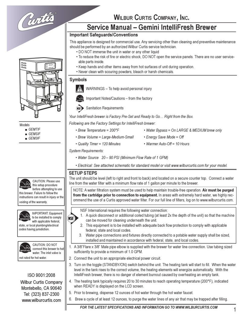
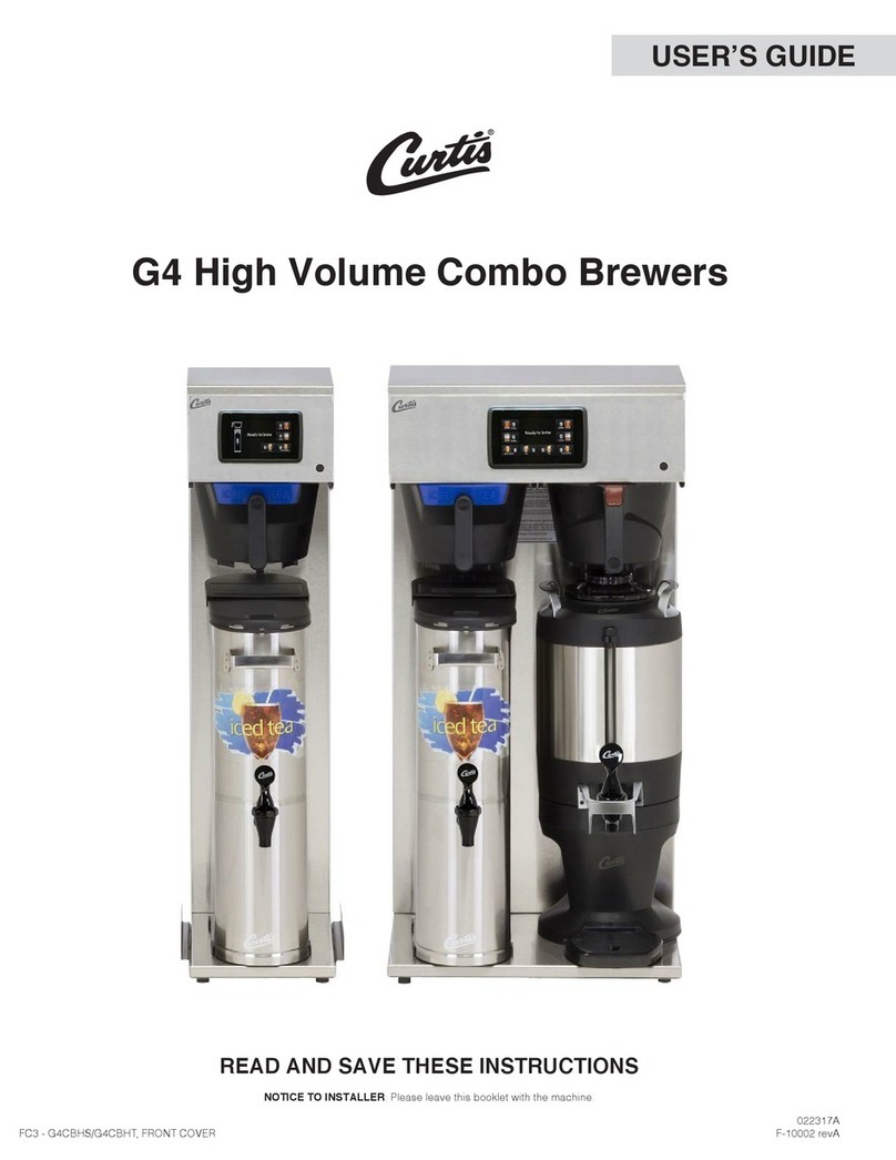
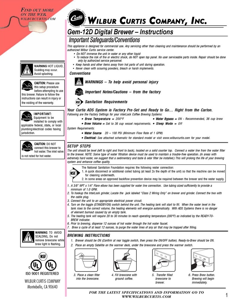
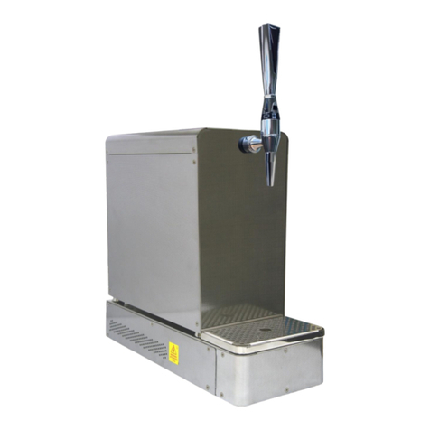
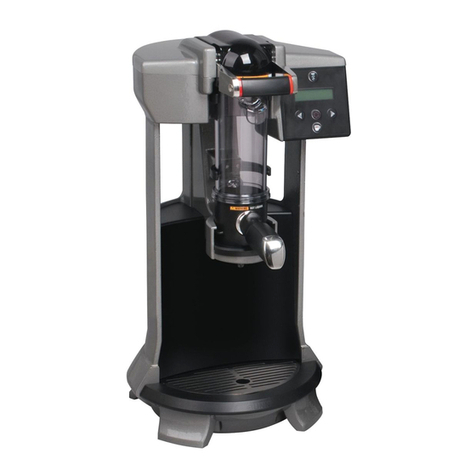
Wilbur Curtis Company ThermoPro Twin User manual

1
Service Manual – ThermoPro Twin & Single Brewers
FOR THE LATEST SPECIFICATIONS AND INFORMATION GO TO WWW.WILBURCURTIS.COM
Important Safeguards
This appliance is designed for commercial use. Any servicing other than cleaning and preventive maintenance should be
performed by an authorized Wilbur Curtis service technician.
•DONOTimmersetheunitinwateroranyotherliquid
•Toreducetheriskofreorelectricshock,DONOTopenservicepanels.Nouserserviceablepartsinside.
•Keephandsandotheritemsawayfromhotsurfacesofunitduringoperation.
•Nevercleanwithscouringpowders,bleachorharshchemicals.
Symbols
WARNINGS – To help avoid personal injury
Important Notes/Cautions – from the factory
Sanitation Requirements
This Curtis Generation 3 Unit is Factory Pre-Set and Ready to Go… Right from the Carton.
FollowingaretheFactorySettingsforyourG3CoffeeBrewingSystems:
•BrewTemperature=200°F •WaterBypass=OnforLARGE&MEDIUMBrewOnly
•BrewVolume=SettoVesselRequirement. •SleepMode=Off
SystemRequirements:
•WaterSource20–90PSI(MinimumFlowRateof1GPM)
•Electrical:Seeattachedschematicforstandardmodelorvisitwww.wilburcurtis.comforyourmodel.
WILBURCURTISCOMPANY
Montebello,CA90640
Models Included
TP2T – ThermoPro Twin
TP2S – ThermoPro Single
CAUTION:DONOT
connectthisbrewertohot
water.Theinletvalveis
notratedforhotwater.
CAUTION:Pleaseuse
this setup procedure
before attempting to use
thisbrewer.Failuretofollowthe
instructions can result in injury or the
voidingofthewarranty.
ISO9001REGISTERED
WARNINGHOTLIQUID,
Scalding may occur.
Avoid splashing.
IMPORTANT:Equipment
to be installed to comply
withapplicablefederal,
state,orlocalplumbing/electrical
codes having jurisdiction.
NSFInternationalrequiresthefollowingwaterconnection:
1. Aquickdisconnectoradditionalcoiledtubing(atleast2xthedepthoftheunit)sothatthemachinecan
be moved for cleaning underneath the unit.
2. Thisequipmentistobeinstalledwithadequatebackowprotectiontocomplywithapplicablefederal,
state and local codes.
3. Waterpipeconnectionsandxturesdirectlyconnectedtoapotablewatersupplyshallbesized,
installedandmaintainedinaccordancewithfederal,state,andlocalcodes.
Setup Steps
Theunitshouldbelocatedonasolidcountertopandleveled(lefttorightandfronttoback).Connectawaterlinefrom
thewaterltertothebrewer.
NOTE:Awaterltrationsystemmustbeinstalledtomaintainatrouble-freeoperation.(Inareaswithextremelyhardwater,
wesuggestthatasedimentaryandtaste&odorlterbeinstalled.)Thiswillprolongthelifeofyourbrewingsystemand
enhancecoffeequality.
Wilbur Curtis Company, inC.
1. A3/8”Flarex3/8”Malepipeelbowissuppliedwiththebrewerforwaterlineconnection.Usetubingsizedsufcientlyto
provideaminimumof1.0GPM.
2. Connecttheunittoanappropriateelectricalpowercircuit.
3. Turnonthetoggle(STANDBY/ON)switchbehindtheunit.Theheatingtankwillstarttoll.Whenthewaterlevelinthe
tankrisestothecorrectvolume,theheatingelementswillenergizeautomatically.
4. Theheatingtankwillrequire20to30minutestoreachoperatingtemperature(200°F),indicatedwhenREADYTO
BREWisdisplayedontheLCDscreen.
5. Priortobrewing,dispense12ouncesofhotwaterthroughthehotwaterfaucet.
6. Brewacycleofatleast12ounces,topurgethewaterlinesofanyairthatmaybetrappedafterlling.
7. Priortobrewing,dispense12ouncesofhotwaterthroughthehotwaterfaucet.
8. Brewacycleofatleast12ounces,topurgethewaterlinesofanyairthatmaybetrappedafterlling.
9. TheThermoProbrewerisnowreadyforoperation.

Your Curtis ADS System is Factory Pre‑Set for Optimum Performance.
Afterconnectiontowaterandpower;thereartoggleswitchmustbeon.Youwillhearabeepsound,indicatingpowerisavailabletothecontroller.
Thecontroldisplays .PressON/OFFbuttonandthescreenwilldisplay .Afterthreeseconds, isdisplayed.
Waterwillllthetank(approximately2-3minutesdependingonwaterowrate).Whentheproperlevelisreached willappearonthescreen.
Ittakesapproximately20minutestoreachsetpointtemperatureof200°F.
Controlwilldisplay whentemperaturereachesthesetpoint(200°F);unitisatbrewingtemperature.
THERMOPRO
WILBUR CURTIS
WILBUR CURTIS WILBUR CURTIS
FILLING . . .
WILBUR CURTIS
HEATING . . .
WILBUR CURTIS
READY TO BREW
2
BREWING INSTRUCTIONS
1.BrewershouldbeON(Conrmatreartoggleswitch,thenpresstheON/OFFbutton).ScreenshouldreadReady-to-Brew.Ifconnectedtoan
InterLockgrinder.Grindershouldbeon.
2.PlaceanemptyThermoProservercenteredbeneaththebrewcone.
6. Selectandpressdesired
brewbutton.Brewingwill
begin immediately.
5. Transferlledbrewcone
tothebrewrails.
3. Placeacleanlterinto
thebrewcone.
4. Fillbrewconewiththe
proper amount of ground
coffee.IfInterlocked,
llthebrewconeatthe
grinder.
WARNINGTOAVOIDSCALDING,Donotremovebrewconewhilebrewlightisashing.

Allprogrammingselectionsareperformedwiththethreecenterbuttons.
Thesymbolsbelowthebuttonsare:
ScrollLEFT
SELECTIONorENTERtosavenewparameter
ScrollRIGHT
IMPORTANTNOTE:
ThermoPro Programming Guide
3

E
27 A
25
26
1
2
34
3
4
5
6
7
8
13
14
15
16
9
10
11
12
17
18
19
20
21 22
23
24
28
2930
31
B
33
4
PARTS DIAGRAM
THERMOPRO
TWINBREWER
TP2T

1
2
3
4
5
5A
5B
6
7
8
9
10
11
12
12A
13
14
15
16
17
18
19
20
21
22
23
24
25
26
27
28
29
30
31
32
33
34
WC-5459
GEM-6
WC-37121*
WC-844-101*
WC-39442
WC-39415
WC-39414
WC-3417
WC-29050
WC-58037-101
WC-847*
WC-2402P
WC-37122*
WC-442
WC-441
WC-1825
WC-8559
WC-8591*
WC-3528
WC-62030
WC-37008
WC-5502-01*
WC-4382
WC-5310*
WC-934-04*
WC-522*
WC-43055
WC-5231*
WC-1438-101*
WC-3765L*
WC-1501
WC-102*
WC-5350*
WC-37176*
WC-13335
WC-37132*
WC-2977-101K*
COVER,TOPWRAP
FILTER,500/PKG(USEWITHWC-3417)
KIT,DUMPVALVEBREWLEFT
VALVE,BY-PASSW/RESISTOR
LABEL,UCMOVERLAYTP2TTWIN3-BATCHCURTIS
LABEL,UCMOVERLAYTWIN2-BATCHCURTIS
LABEL,UCMOVERLAYTWIN1-BATCHCURTIS
BREWCONE,ASSYW/SPLASHPOCKETBROWNCOF
SPRAYHEAD,ADVANCEDFLOW
COVER,CENTERWRAPTP90º
VALVE,WATERINLET2GPM120V10W
ELBOW,3/8”FLx3/8”NPTPLATED
KIT,DUMPVALVEBREWRIGHT
SOLENOID,LOCKBREWCONERIGHT/LEFT120V
SOLENOID,LOCKBREWCONELEFT(OLDERUNITS)
FAUCET,ASSEMBLYHOTWATERTP2S
RELAY,SOLIDSTATEW/INTEGRATEDHTSNK
CAPACITOR
LEG,4”ADJUSTABLE3/8-16THRDITALIANSTYLE
TANK,COMPLETETP2TULTEMFITTINGS
KIT,TANKLIDROUND
KIT,PROBE,ASSYWATERLEVEL
GUARD,SHOCKHEATINGELEMENTS
TUBE,5/16”I.D.X1/8”SILICONE
ELEMENT,HEATING2.5KW220VW/JAMNUTS
THERMOSTAT,RESET
GUARD,SHOCKRESETTHERMOSTAT
COMPOUND,SILICONE
SENSOR,HEATINGTANK
KIT,VALVEREPAIRUSEONWC-825&WC-826
FUSEHOLDER
SWITCH,TOGGLE125/250VACRESISTIVE
TUBE,½IDx1/8WSILICONE
KIT,UCM&LABELINSTRUCTIONSTHERMOPRO
HARNESSASSY,COMPLETETP2T10(NOTSHOWN)
KIT,DUMPVALVEWC-820WC-821,WC-844
KIT,SPRAYHEADFITTINGPLASTIC
ITEM № PART № DESCRIPTION
*RECOMMENDEDPARTSTOSTOCK.
ILLUSTRATED
PARTS LIST
THERMOPRO
TWINBREWER
TP2T
5

6
PARTS DIAGRAM
THERMOPRO
SINGLEBREWER
TP2S
26
3
12
2
6
28

1
2
3
4
5
5A
5B
6
7
8
9
10
11
12
13
14
14A
15
16
17
18
18A
19
20
21
22
22A
23
24
24A
25
26
27
28
29
30
31
32
WC-61509
GEM-6
WC-3765L*
WC-844-101*
WC-39444
WC-39417
WC-39416
WC-3417
WC-29050*
WC-58037-101
WC-847*
WC-1501
WC-37122*
WC-37132*
WC-1825
WC-8559*
WC-8556-101
WC-8591*
WC-3528
WC-5350*
WC-5853-102
WC-5851
WC-5502-01*
WC-4382
WC-5310*
WC-904-04
WC-906-04*
WC-522*
WC-62031
WC-62032
WC-103*
WC-5231*
WC-1438-101*
WC-723*
WC-43055
WC-43062*
WC-13286
WC-2977-101K*
COVER,TOPWRAP
FILTERS,500/PKG(USEWITHWC-3417)
KIT,INLETVALVEREPAIRUSEONWC-826L/WC-847
VALVE,ADJBY-PASS
LABEL,UCMOVERLAYTP2S3-BATCHCURTIS
LABEL,UCMOVERLAYTP2S1-BATCHCURTIS
LABEL,UCMOVERLAYTP2S2-BATCHCURTIS
BREWCONE,ASSYW/SPLASHPOCKETBROWNCOF
SPRAYHEADASSY,ADVANCEDFLOW
COVER,CENTERWRAP
VALVE,WATERINLET2GPM120V10W
FUSEHOLDERW/5AFUSE
KIT,DUMPVALVEBREWRIGHT
KIT,DUMPVALVEWC-820WC-821,WC-844
FAUCETASSY,HOTWATERTP2S/2T
RELAY,SOLIDSTATE40AW/HEATSINK
HEATSINK,ASSYW/OPTICALBD(OLDERUNITS)
CAPACITOR,X2
LEG,4”ADJUSTABLE3/8-16THREADITALIANSTYLE
TUBE,½IDx1/8WSILICONE
COVER,TOPHEATINGTANKGENUSE
COVER,TANKW/NOTCHES
KIT,PROBE,ASSYWATERLEVEL
GUARD,SHOCKHEATINGELEMENTS
TUBE,5/16”I.D.X1/8”SILICONE(NOTSHOWN)
ELEMENT,HEATING1.6KW120VW/JAMNUTS
ELEMENT,HEATING2KW220VW/JAMNUTS
THERMOSTAT,RESET
TANK,COMPLETETP2SDVULTEMFITTINGS
TANK,COMPLETETP2SULTEMFITTINGS
SWITCH,TOGGLENON-LITDPST25A125/250VACRST
COMPOUND,SILICONE
SENSOR,HEATINGTANK
CONTROLMODULE,120VTP2S/TP2T
GUARD,SHOCKRESETTHERMOSTAT
GASKET,TANKLID
HARNESSASSY,COMPLETETP2S
KIT,SPRAYHEADFITTINGULTEM
*RECOMMENDEDPARTSTOSTOCK.
ILLUSTRATED
PARTS LIST
THERMOPRO
SINGLEBREWER
TP2S
7
ITEM № PART № DESCRIPTION

8

9

Cleaning the ThermoPro
Regularcleaningandpreventivemaintenanceisessentialinkeepingyourcoffeebrewerlookingandworkinglikenew.Tocleanthecoffee
brewerandcomponents,prepareamildsolutionofdetergentandwarmwater.
CAUTION – Donotusecleansers,bleachliquids,powdersoranyothersubstancecontainingchlorine.Theseproductspromotecorrosionand
willpitthestainlesssteel.USEOFTHESEPRODUCTSWILLVOIDTHEWARRANTY.
DAILY CLEANING
1. Wipeexteriorsurfaceswithadampcloth,removingspillsanddebris.
2. Slidethebrewconeoutandcleanit.Wipethesprayheadareawithaclothsoakedinamilddetergentsolution.
3. Rinseanddrythebrewconeandsprayheadarea.
4. Draindriptraysofcoffee.
5. Drythetray.
WEEKLY CLEANING
1. Turnoffunitatthepowerswitch,behindtheunit.Allowthebrewertocool.
2. Cleanthesprayheadanddomeplatearea.
a. Removethesprayhead,unscrewingcounterclockwisefromthedomeplate.
b. Thoroughly clean and rinse the dome plate area.
c. Cleanthebrewconerailswithabrushsoakedwithamilddetergentsolution.Rinsetheareawithaclothsoakedwithcleanwater,
removing any residual detergent.
d. Drythearea.
c. Attach the sprayhead.
Cleaning the Thermoserver
1. Draincoffeefromtheserver.
2. Fillthelinerwithamilddetergentsolutionandletitstandfor10to15minutes.
3. Afterabout15minutestakeaspongebrushandscruboutthestainlesssteelliner.
4. Whenclean,drainoutthesoapysolutionfromtheserver.
5. Filltheserverwithcleanwatertorinsedetergentfrominsidetheunit.Repeatthisrinsinguntilthewaterrunsclear.
CLEANING OF THERMOSERVER FAUCET
1. Removethefaucethandleassembly.Takeholdofthebonnetandturncounterclockwisetounscrewitfromthefaucet.
2.Cleanthehandleassemblywithamilddetergentsolution.Whenclean,rinsethehandlewithwater.Inspectforcracks
or tears in the seat cup. Replace if damaged.
3. Clean the coffee level gauge glass.
a. Remove the sight glass cover by pulling up and off from the front of the server.
b. Usingthenarrowbrushprovidedforthispurpose,brushouttheinsideoftheglasswithadetergentsolution.
Rinse the sight glass tube of all detergent residue.
c. Payspecialattentiontothesmallgaugeglassliquidlevelholeonthebodyofthefaucet.Youcanbrushthis
outwithasmallpipecleaner.
d. Replacethesightglass.Makesurethetopandbottomsiliconesealsareseated.
10

Page Intentionally Left Blank
11

11/11/[email protected].ecn15461.revM
3/6/[email protected].ecn14810.revL
10/10/[email protected].ecn14475.ear1067
WILBUR CURTIS CO., INC.
6913 Acco St., Montebello, CA 90640-5403 USA
Phone: 800/421-6150 Fax: 323-837-2410
Web Site: www.wilburcurtis.com
Printed in U.S.A. 11/2013 F-3263-S Rev M
12
ProductWarrantyInformation
TheWilburCurtisCompanycertiesthatitsproductsarefreefromdefectsinmaterialandworkmanshipundernormaluse.Thefollowinglimited
warrantiesandconditionsapply:
3 Years,PartsandLabor,fromOriginalDateofPurchaseondigitalcontrolboards.
2 Years,Parts,fromOriginalDateofPurchaseonallotherelectricalcomponents,ttingsandtubing.
1 Year,Labor,fromOriginalDateofPurchaseonallelectricalcomponents,ttingsandtubing.
Additionally,theWilburCurtisCompanywarrantsitsGrindingBurrsforForty(40)monthsfromdateofpurchaseor40,000poundsofcoffee,
whichevercomesrst.StainlessSteelcomponentsarewarrantedfortwo(2)yearsfromdateofpurchaseagainstleakingorpittingandreplace-
mentpartsarewarrantedforninety(90)daysfromdateofpurchaseorfortheremainderofthelimitedwarrantyperiodoftheequipmentinwhich
the component is installed.
Allin-warrantyservicecallsmusthavepriorauthorization.ForAuthorization,calltheTechnicalSupportDepartmentat1-800-995-0417.Effective
dateofthispolicyisApril1,2003.
Additional conditions may apply. Go to www.wilburcurtis.comtoviewthefullproductwarrantyinformation.
CONDITIONS & EXCEPTIONS
Thewarrantycoversoriginalequipmentattimeofpurchaseonly.TheWilburCurtisCompany,Inc.,assumesnoresponsibilityforsubstitutereplace-
mentpartsinstalledonCurtisequipmentthathavenotbeenpurchasedfromthe
WilburCurtisCompany,Inc.TheWilburCurtisCompanywillnotacceptanyresponsibilityifthefollowingconditionsarenotmet.Thewarranty
doesnotcoverandisvoidunderthefollowingcircumstances:
1) Improper operation of equipment: The equipment must be used for its designed and intended purpose and function.
2) Improper installation of equipment: This equipment must be installed by a professional technician and must comply with all local electrical,
mechanical and plumbing codes.
3) Improper voltage: Equipment must be installed at the voltage stated on the serial plate supplied with this equipment.
4) Improper water supply: This includes, but is not limited to, excessive or low water pressure, and inadequate or uctuating water ow rate.
5) Adjustments and cleaning: The resetting of safety thermostats and circuit breakers, programming and temperature adjustments are the
responsibility of the equipment owner. The owner is responsible for proper cleaning and regular maintenance of this equipment.
6) Damaged in transit: Equipment damaged in transit is the responsibility of the freight company and a claim should be made with the carrier.
7) Abuse or neglect (including failure to periodically clean or remove lime accumulations): Manufacturer is not responsible for variation
in equipment operation due to excessive lime or local water conditions. The equipment must be maintained according to the manufacturer’s
recommendations.
8) Replacement of items subject to normal use and wear: This shall include, but is not limited to, light bulbs, shear disks, “0” rings, gaskets,
silicone tube, canister assemblies, whipper chambers and plates, mixing bowls, agitation assemblies and whipper propellers.
9) Repairs and/or Replacements are subject to our decision that the workmanship or parts were faulty and the defects showed up under normal
use. All labor shall be performed during regular working hours. Overtime charges are the responsibility of the owner. Charges incurred by
delays, waiting time, or operating restrictions that hinder the service technician’s ability to perform service is the responsibility of the owner
of the equipment. This includes institutional and correctional facilities. The Wilbur Curtis Company will allow up to 100 miles, round trip, per
in-warranty service call.
RETURN MERCHANDISE AUTHORIZATION: All claims under this warranty must be submitted to the Wilbur Curtis Company Technical
Support Department prior to performing any repair work or return of this equipment to the factory. All returned equipment must be repackaged
properly in the original carton. No units will be accepted if they are damaged in transit due to improper packaging. NO UNITS OR PARTS WILL
BE ACCEPTED WITHOUT A RETURN MERCHANDISE AUTHORIZATION (RMA). RMA NUMBER MUST BE MARKED ON THE CARTON
OR SHIPPING LABEL. Allin-warrantyservicecallsmustbeperformedbyanauthorizedserviceagent.CalltheWilburCurtisTechnicalSup-
portDepartmenttondanagentnearyou.
This manual suits for next models
3
Table of contents
Other Wilbur Curtis Company Brewing System manuals

Wilbur Curtis Company
Wilbur Curtis Company Gem-12D User manual

Wilbur Curtis Company
Wilbur Curtis Company G4CBHS User manual

Wilbur Curtis Company
Wilbur Curtis Company Gemini IntelliFresh GEMTIF User manual

Wilbur Curtis Company
Wilbur Curtis Company Gemini GEM-612ILD User manual

Wilbur Curtis Company
Wilbur Curtis Company D1000GT User manual
Popular Brewing System manuals by other brands

Brouwland
Brouwland COOL BREWING 016.001.0 user guide

Newco
Newco Bistro Touch BISTRO-TCH Operating instructions manual

Curtis
Curtis ThermoPro G4 Series user guide

Newco
Newco DB2A Installation & operating manual

Bloomfield
Bloomfield 8740 owner's manual

Curtis
Curtis G3 Gemini IntelliFresh GEMTIF10A2000 user guide