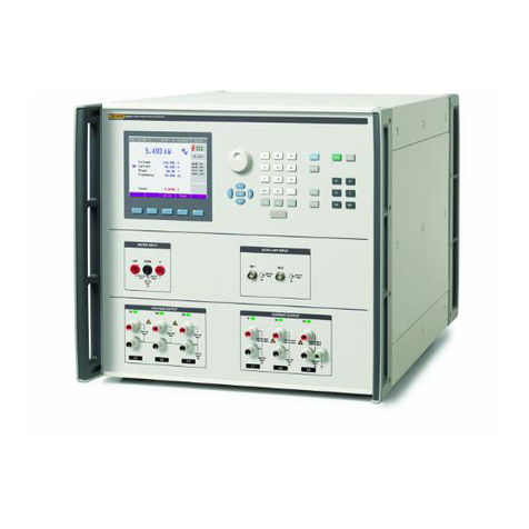
Fluke 6200-2 User manual

September 2013
© 2013 Fluke Corporation. All rights reserved. Specifications are subject to change without notice.
All product names are trademarks of their respective companies.
6200-2
Appliance Tester
Users Manual

LIMITED WARRANTY AND LIMITATION OF LIABILITY
Each Fluke product is warranted to be free from defects in material and workmanship under normal use and
service. The warranty period is two years and begins on the date of shipment. Parts, product repairs, and
services are warranted for 90 days. This warranty extends only to the original buyer or end-user customer of
a Fluke authorized reseller, and does not apply to fuses, disposable batteries, or to any product which, in
Fluke's opinion, has been misused, altered, neglected, contaminated, or damaged by accident or abnormal
conditions of operation or handling. Fluke warrants that software will operate substantially in accordance
with its functional specifications for 90 days and that it has been properly recorded on non-defective media.
Fluke does not warrant that software will be error free or operate without interruption.
Fluke authorized resellers shall extend this warranty on new and unused products to end-user customers
only but have no authority to extend a greater or different warranty on behalf of Fluke. Warranty support is
available only if product is purchased through a Fluke authorized sales outlet or Buyer has paid the
applicable international price. Fluke reserves the right to invoice Buyer for importation costs of
repair/replacement parts when product purchased in one country is submitted for repair in another country.
Fluke's warranty obligation is limited, at Fluke's option, to refund of the purchase price, free of charge repair,
or replacement of a defective product which is returned to a Fluke authorized service center within the
warranty period.
To obtain warranty service, contact your nearest Fluke authorized service center to obtain return
authorization information, then send the product to that service center, with a description of the difficulty,
postage and insurance prepaid (FOB Destination). Fluke assumes no risk for damage in transit. Following
warranty repair, the product will be returned to Buyer, transportation prepaid (FOB Destination). If Fluke
determines that failure was caused by neglect, misuse, contamination, alteration, accident, or abnormal
condition of operation or handling, including overvoltage failures caused by use outside the product’s
specified rating, or normal wear and tear of mechanical components, Fluke will provide an estimate of repair
costs and obtain authorization before commencing the work. Following repair, the product will be returned to
the Buyer transportation prepaid and the Buyer will be billed for the repair and return transportation charges
(FOB Shipping Point).
THIS WARRANTY IS BUYER'S SOLE AND EXCLUSIVE REMEDY AND IS IN LIEU OF ALL OTHER
WARRANTIES, EXPRESS OR IMPLIED, INCLUDING BUT NOT LIMITED TO ANY IMPLIED WARRANTY
OF MERCHANTABILITY OR FITNESS FOR A PARTICULAR PURPOSE. FLUKE SHALL NOT BE LIABLE
FOR ANY SPECIAL, INDIRECT, INCIDENTAL OR CONSEQUENTIAL DAMAGES OR LOSSES,
INCLUDING LOSS OF DATA, ARISING FROM ANY CAUSE OR THEORY.
Since some countries or states do not allow limitation of the term of an implied warranty, or exclusion or
limitation of incidental or consequential damages, the limitations and exclusions of this warranty may not
apply to every buyer. If any provision of this Warranty is held invalid or unenforceable by a court or other
decision-maker of competent jurisdiction, such holding will not affect the validity or enforceability of any other
provision.
Fluke Corporation
P.O. Box 9090
Everett, WA 98206-9090
U.S.A.
Fluke Europe B.V.
P.O. Box 1186
5602 BD Eindhoven
The Netherlands
11/99
i
Table of Contents
Title Page
Introduction........................................................................................................ 1
How to Contact Fluke ........................................................................................ 1
Unpack the Tester .............................................................................................. 2
Safety Information ............................................................................................. 2
Features.............................................................................................................. 4
Front Panel Description ................................................................................. 4
Pushbuttons.................................................................................................... 5
Beeper............................................................................................................ 5
Display........................................................................................................... 6
Power-Up and Warning Display Messages ....................................................... 7
Tester Setup ....................................................................................................... 8
Safe Appliance Tests ......................................................................................... 9
Single Test Mode........................................................................................... 9
Continuous Test Mode .................................................................................. 9
Stop a Test ..................................................................................................... 10
How to Save Test Results.............................................................................. 10
Visual Inspection ........................................................................................... 10
Earth Bond Test (RPE).................................................................................... 11
Insulation Test (RISO)..................................................................................... 12
Substitute Leakage Current Test (ISUBSTITUTE) ............................................... 13
Touch Current Test (ITOUCH) .......................................................................... 14
Load/Leakage Current Test ........................................................................... 16
IEC Lead Test ........................................................................................... 17
PELV Test................................................................................................. 18
Memory.............................................................................................................. 19
Save Test Results........................................................................................... 19
Clear Memory................................................................................................ 19
Print Test Results ............................................................................................... 20
Maintenance....................................................................................................... 20
How to Clean................................................................................................. 20
Calibration ..................................................................................................... 20
Accessories.................................................................................................... 21
Specifications..................................................................................................... 22
General Specifications................................................................................... 22
Test Specifications......................................................................................... 22

6200-2
Users Manual
ii

iii
List of Tables
Table Title Page
1. Shipment Box Contents.......................................................................................... 2
2. Symbols.................................................................................................................. 3
3. 6200-2 Appliance Tester ........................................................................................ 4
4. Pushbutton Controls ............................................................................................... 5
5. Beeper Sounds........................................................................................................ 5
6. Display Features..................................................................................................... 6
7. Display Messages................................................................................................... 7
8. Standard Accessories ............................................................................................. 21
9. Optional Accessories.............................................................................................. 21

6200-2
Users Manual
iv

v
List of Figures
Figure Title Page
1. Bond Zero Connections.......................................................................................... 8
2. Bond Test Connections .......................................................................................... 11
3. Insulation and Substitute Leakage Test Connections Class II................................ 13
4. Touch Current Connections ................................................................................... 15
5. Load/Leakage Connections .................................................................................... 16
6. IEC-Lead Test Connections ................................................................................... 18

6200-2
Users Manual
vi

1
Introduction
The Fluke model 6200-2 Appliance Tester (Tester or Product) is designed to do tests that
ensure the integrity of electrical equipment / portable appliances:
•Earth Bond (RPE)
•Insulation (RISO)
•Substitute Leakage Current
•Touch Current
•Load/Leakage
•IEC Lead
•PELV
How to Contact Fluke
To contact Fluke, call one of the following telephone numbers:
•Technical Support USA: 1-800-44-FLUKE (1-800-443-5853)
•Calibration/Repair USA: 1-888-99-FLUKE (1-888-993-5853)
•Canada: 1-800-36-FLUKE (1-800-363-5853)
•Europe: +31 402-675-200
•Japan: +81-3-6714-3114
•Singapore: +65-6799-5566
•Anywhere in the world: +1-425-446-5500
Or, visit Fluke's website at www.fluke.com.
To register your product, visit http://register.fluke.com.
To view, print, or download the latest manual supplement, visit
http://us.fluke.com/usen/support/manuals.

6200-2
Users Manual
2
Unpack the Tester
The purchase of a Tester includes the items in Table 1. If the Tester is damaged or an item is
missing, contact the place of purchase immediately.
Table 1. Shipment Box Contents
Description QTY
6200-2 Appliance Tester 1
Alligator Clip (Crocodile Clip) 1
Test Lead 1
Test Probe for Touch Current 1
Hard Case 1
CD with Users Manual 1
Quick Reference Card 1
Safety Information 1
Safety Information
A Warning identifies hazardous conditions and procedures that are dangerous to the user. A
Caution identifies conditions and procedures that can cause damage to the Product or the
equipment under test. The Tester must only be used by a suitably trained and competent
person.
Carefully read the safety information before you use the Tester.
Warning
To prevent possible electrical shock, fire, or personal injury:
•Read all safety information before you use the Product.
•Use the Product only as specified, or the protection supplied by the
Product can be compromised.
•Do not use the Product if it operates incorrectly.
•Do not use the Product if it is damaged.
•Do not use test leads if they are damaged. Examine the test leads for
damaged insulation, exposed metal, or if the wear indicator shows.
Check test lead continuity.
•Use this Product indoors only.
•Do not use the Product around explosive gas, vapor, or in damp or
wet environments.
•Use only the mains power cord and connector approved for the
voltage and plug configuration in your country and rated for the
Product.
•Replace the mains power cord if the insulation is damaged or if the
insulation shows signs of wear.
•Carefully read all instructions.

Appliance Tester
Safety Information
3
•Do not apply more than the rated voltage, between the terminals or
between each terminal and earth ground.
•Limit operation to the specified measurement category, voltage, or
amperage ratings.
•Measure a known voltage first to make sure that the Product
operates correctly.
•Use only current probes, test leads, and adapters supplied with the
Product.
•Do not use a current measurement as an indication that a circuit is
safe to touch. A voltage measurement is necessary to know if a
circuit is hazardous.
•Keep fingers behind the finger guards on the probes.
•The Product shall not be used for measurements in electrical
installations.
•When conducting tests, do not touch the appliance as some tests
involve high voltages and high currents.
•Never open the Product’s case because dangerous voltages are
present. There are no user-replaceable parts in the Product.
•The Product has been set for a nominal 240 V ac, 50 Hz operation, it
must never be connected to a higher voltage.
•The Product may only be connected to a correctly wired mains
socket protected for a maximum current rating of 10 A (AU), 13 A
(UK), or 16 A (DE, NL).
•The mains supply is never to be connected to the IEC lead test
connector or to the appliance test connector.
•If the Product continuously emits a two-tone sound, you should
unplug it immediately as this indicates a dangerous condition.
Table 2 is a list of symbols used on the Product or in this manual.
Table 2. Symbols
Symbol Description
Risk of danger. Important information. See manual.
Hazardous voltage. Risk of electric shock.
Conforms to requirements of European Union and European Free Trade Association.
VDE Association for Electrical, Electronic & Information Technologies.
Double Insulated (Class II) Equipment
Earth Ground
This product complies with the WEEE Directive (2002/96/EC) marking requirements. The
affixed label indicates that you must not discard this electrical/electronic product in domestic
household waste. Product Category: With reference to the equipment types in the WEEE
Directive Annex I, this product is classed as category 9 “Monitoring and Control
Instrumentation product. Do not dispose of this product as unsorted municipal waste. Go to
Fluke's website for recycling information.

6200-2
Users Manual
4
Features
The Tester can perform all the tests required for Class I and Class II appliances and conforms
to safety standard EN61010. All features for manual tests and low volume applications are
accessible from the front panel.
Front Panel Description
The connectors, controls and indicators of the Tester are shown in Table 3.
Table 3. 6200-2 Appliance Tester
SWITCH ON APPLIANCE FOR ALL TESTS
IEC
BOND 25A/200mA
TOU CH P ROBE
INSULATION PROBE
CLASS II
PROBE PELV
TEST SOCKET
230V 50Hz / MAX 13A
BOND ZERO
6200-2
APPLIANCE TESTER
I
PE
< 3.5mA
(0.75mA PORTABLE
APPLIANCE)
INSULATION I SUB
BOND ZERO
IEC LEAD
EARTH BOND
LOAD / LEAK ITOUCH
I
TOUCH
< 0.25 mA
R
ISO
> 1.0M Class I R
ISO
> 2.0M Class II
RPE < 0.1
R
ISO
> 1.0M Class I
R
PE
200mA, R
PE
25A
R
PE
< 0.1 + LEAD
PROBE ONLY WITH
CLASS II APPLIANCE
1
8
3
7
45
2
Euro United Kingdom
Australia
6
hdc01.eps
No. Description
Liquid Crystal Display (LCD)
Socket to connect IEC lead for IEC Lead test
Earth connection to zero the Earth Bond test lead
Socket to connect test lead and crocodile clip for Earth Bond test
Socket to connect test probe for Insulation test, Touch Current test, Substitute Leakage test and
PELV test
Appliance Test Socket
2 USB Ports
Pushbuttons (see Table 4)

Appliance Tester
Features
5
Pushbuttons
Use the pushbuttons in Table 4 to control operation of the Tester.
Table 4. Pushbutton Controls
MEM
CLEAR
PRINT
BOND
200 mA
BOND
25 A
INSUL-
ATION
I
SUB
LOAD/
LEAK
I
TOUCH
IEC
LEAD ZERO
1 2 43 5 6
7
89101112
hdc09.eps
No. Function No. Function
Start the 200 mA Earth Bond test Clear stored data
Start the high current Earth Bond test Print test results
Start the combined Load/Earth Leakage
Current test Start zeroing the Earth Bond test
Start the Insulation test Start the IEC Lead test
Start the Touch Current test Start the Substitute Leakage Current test
Store test results Stop the current action and return to idle
screen
Beeper
The Tester can make several types of beeper sounds, see Table 5.
Table 5. Beeper Sounds
Sound Explanation
Click A button is pushed.
1 beep A test passed.
2 beeps close together - A test failed.
- Warning, see display.
- The STOP button is pushed, the current action is stopped.
1 long beep A continuous non-live test has been started.
2 beeps + 1 long beep A continuous live test has been started.
Continuous 2 tone sound Dangerous condition! Unplug the unit immediately!

6200-2
Users Manual
6
Display
Table 6 is a list of the display features and their functions.
Table 6. Display Features
>0.10
+LEAD?
INSULATION
<2.0 M CII
25 A
200 mA
EARTH BOND
I
SUBSTITUTE
I
TOUCH
LOAD PE LEAK
IEC LEAD
Limit
V
AC
mA
kVAW
M
PRINT
R
ISO
U
N-PE
U
L-N
R
PE
Hz
MULTI RESULTS
seconds
<1.0 M CI
memory
1 2 3 4 5
6
8
9
10
11
12
7
hdc08.eps
No. Description
Caution! Risk of Danger. Refer to Manual.
Check the mains polarity.
Multiple test results show in succession.
Printing results.
Fluke printer is connected.
Tests and limits.
A single test has passed or failed.
Readout and measurement units field, error message field.
> result overflow
< or underflow
Bond test zero function.
Ø displays if the bond test has been zeroed.
Caution! Risk of Electric Shock.
Displays when you store/clear results.
Neutral-Protective Earth voltage too high.
Mains voltage out of limits.
Mains frequency out of limits.

Appliance Tester
Power-Up and Warning Display Messages
7
Power-Up and Warning Display Messages
Warning
To prevent possible electrical shock, fire, or personal injury:
•Read the safety information before you power up the Tester.
•Connect an approved three-conductor mains power cord to a grounded
power outlet.
•Do not use a two-conductor mains power cord unless you install a
protective ground wire to the Product ground terminal before you
operate the Product.
•Make sure that the Product is grounded before use.
The Tester will power up when you connect it to the mains supply.
Disconnect the mains plug to power down the Tester.
At power up the Tester performs a selftest and shows the software version.
After power up, the display indicates the mains supply voltage. This screen is referred to
throughout this manual as the idle screen.
If the Tester detects special conditions at power up, such as a dangerous condition, a warning
message indicates the condition.
Table 7 is a list of the messages that can show when you power up the Tester. The values are
examples and can differ from actual values shown on the display.
Table 7. Display Messages
Display Explanation
Στ Selftest
1.18 Software version is shown after power on.
230 VAC Mains supply voltage, idle screen.
UN-PE 50 VAC Mains problem, unplug unit! No test possible.
UL-N 195 VAC Mains voltage too low. No test possible.
UL-N 265 VAC Mains voltage too high. No test possible.
< 48 Hz Mains frequency too low. No test possible.
> 52 Hz Mains frequency too high. No test possible.
Memory full.
75 Memory nearly full (>75 %).
+ number Tester failure, contact Fluke support.
+ number Dangerous Tester failure. Unplug the Tester, prevent it from being used, and contact
Fluke for repair.
UN-PE 71 The Neutral-Earth voltage is dangerously high. Unplug the Tester!
75 The mains polarity is incorrect. Unplug the Tester!
UN-PE 77 Mains supply earth connection is missing/open circuit. Unplug the Tester!

6200-2
Users Manual
8
Tester Setup
The only requirement to set up the Tester is to zero the earth bond test. For correct earth bond
test results you must zero the earth bond lead to eliminate its resistance:
•when you set up your new Tester. Earth bond tests are locked out unless the bond zero
icon ∅is on.
•occasionally, dependent on the condition of the bond socket and the test lead plug, a dirty
plug/socket can result in a significant contact resistance.
To zero the test lead:
1. Attach the probe to the test lead and insert the test lead plug into the EARTH BOND
socket, see Figure 1.
2. Firmly attach the probe to the BOND ZERO connector on the Tester.
3. Push . The display shows a countdown for the test progress.
4. When zero is complete, test lead resistance is subtracted from the bond test result. A
readout of >1.99 cannot be compensated for and the bond test is locked out.
6200-2
APPLIANCE TESTER
MEM
PRINT
BOND
200 mA BOND
25 A INSUL-
ATION
I
SUB
LOAD/
LEAK
I
TOUCH
IEC
LEAD ZERO
CLEAR
I
PE
<3 .5mA
(0.75mA PORTABLE
APPLIANCE)
INSULATION I SUB
BOND ZERO
IECLEAD
EARTH BOND
LOAD / LEAKITOUCH
I
TOUCH
<0.25 mA
R
ISO
>1.0MClassIR
ISO
> 2.0MClassII
RPE< 0.1
R
ISO
> 1.0MClass I
R
PE
200mA, R
PE
25A
R
PE
<0.1 + LEAD
PROBE ONLY WITH
CLASS II APPLIANCE
200
APPLIANCE TESTER
INSU
BOND ZERO
EARTHBOND
/LE
R
PE
200mA,R
PE
25A
R
PE
< 0.1 + LEAD
hdc07.eps
Figure 1. Bond Zero Connections
The Tester saves the zero value so you will not need to repeat the operation every time you
use the Tester. If the Earth Bond test has been zeroed, the idle screen and subsequent earth
bond test results are marked with ∅, for example:
∅0.09 Ω

Appliance Tester
Safe Appliance Tests
9
Safe Appliance Tests
Warning
To prevent possible electrical shock, fire, or personal injury:
•Before you start any tests, you are strongly advised to make
reference to the Electricity at Work Regulations 1989 and any
relevant publications from the Health and Safety Executive.
•The appliance must be switched on for all tests.
•During tests, do not touch the appliance as some tests involve high
voltages and high currents.
•The tests should only be performed by competent persons who are
familiar with the requirements of the type of tests suitable for
portable appliances.
•It is potentially hazardous for both user and appliance should the
wrong type of tests be undertaken or if a test is carried out in an
incorrect sequence.
•It is important that you fully understand the various tests required
and how they should be performed.
•The appliance must have passed the visual inspection, the earth
bond test (Class I), and the insulation test (in this sequence) before
any other test. If any of these tests fail, further tests must be stopped
and any faults must be rectified.
•During the load/leakage test and the touch current test, the appliance
is energized at mains voltage. For this purpose, switch on the
appliance. Appliances driven by motors or equipped with heating
units may present a danger during a test (comply with appliance
instruction manual!). Please ensure that the appliance is in a safe
condition to operate and secure before tests.
You can do tests in a single test mode or in a continuous test mode.
Single Test Mode
To do a single non-live test, push the test button and then release it.
To do a single live test (load/leakage and touch current), hold down the test button and
release it after the second beep, before you hear a third long beep.
The Tester connects the test supply, performs one test, disconnects the test supply and holds
the result on the display.
Continuous Test Mode
To start a continuous non-live test, hold down the test button for at least 2 seconds. You will
hear a long beep to indicate the Tester is in the continuous mode.
To start a continuous live test (load/leakage and touch current) hold down the test button until
you hear two beeps followed by a third beep.
The Tester connects the test supply, makes the first test and displays the first result. Then the
Tester continues to measure and display results without disconnecting the test supply. The
maximum test time is 8 minutes. After which the test terminates.

6200-2
Users Manual
10
To stop a continuous test, push the test button again. The Tester disconnects the test supply, and
holds the last test result on the display.
Note
1. Fuse/L-N Pre-Test is performed as part of live tests (Touch Current and
Load/Leakage Current Test). The pre-test verifies the fuse and lead continuity
with a low voltage signal across the appliances phase and neutral pins.
Very low power appliances, or appliances with electronically controlled on/off
switches or with an inductance may fail this test. In this case the symbol
will appear.
To enable you to test these appliances you can skip the Fuse/L-N Loop Pre-
test. To perform the test on appliances that fail the Fuse/L-N Loop Pre-test:
•Release the appropriate function key, push and hold it until your hear the
second indication beep, but release it before the third long beep.
•To start a continuous test release the appropriate function key, push and
hold it until your hear a third long beep.
2. The measurement unit blinks for an active measurement (for example, Ω, MΩ,
mA) during a continuous test.
3. The IEC-Lead test cannot be done in the continuous test mode.
Stop a Test
Push to immediately end a test that is in progress, make the Tester safe, and then show the
idle screen. Test results do not show on the display.
How to Save Test Results
To save the result after a test is complete, push . The actual test result is saved into
memory. The display shows the number that has been assigned to the record, for example:
5.
For detailed information refer to Memory on page 19.
Visual Inspection
Before any test, check the appliance for:
•condition of the appliance cables, for example, no cuts, cracks or any physical damage to
the outer insulation layer.
•condition of the plug, cable securely attached, no signs of overheating, and that the
correct value of fuse is fitted.
•any signs of damage, and that any mains or control switches will physically switch on
and off.
•any sockets for signs of overheating or physical damage.

Appliance Tester
Safe Appliance Tests
11
Earth Bond Test (RPE)
The test checks the resistance between the earth pin of the appliance cable plug and the
exposed metalwork on the appliance. The test applies to Class I appliances that have current
ranges of 200 mA and 25 A (UK, NL, AU) or 10 A (DE).
Remarks:
•To enable the bond test and to obtain correct bond test results you must have zeroed the
test lead, see Figure 1.
•High current bond test 25 A (UK, NL, AU) and 10 A (DE).
•High current bond test will periodically drop back to 200 mA test to prevent the Tester
from overheating.
•You should use the 200 mA test current for certain appliances. Please refer to the
appliance test standards and guidance material.
To perform the Earth Bond test:
1. Connect the appliance and the earth bond test lead as indicated on the Tester, see
Figure 2. Connect the crocodile clip to an exposed conductive part on the appliance. Do
not use the probe for a bond test >10 A. The probe is rated for 10 A only.
MEM
PRINT
BOND
200mABOND
25 A INSUL-
ATION
I
SUB
LOAD/
LEAK
I
TOUCH
IEC
LEAD ZERO
CLEAR
I
PE
<3.5mA
(0.75mA PORTABLE
APPLIANCE)
INSULATIONISUB
BOND ZERO
IECLEAD
EARTHBOND
LOAD / LEAK ITOUCH
I
TOUCH
<0.25 mA
R
ISO
>1.0M ClassI R
ISO
> 2.0M ClassII
RPE <0.1
R
ISO
> 1.0M ClassI
R
PE
200mA,R
PE
25A
R
PE
< 0.1+LEAD
PROBEONLYWITH
CLASS II APPLIANCE
6200-2
APPLIANCETESTER
hdc11.eps
Figure 2. Bond Test Connections
2. Push or to start the 200 mA test or the high current test:
•Single test push momentarily
•Continuous test hold down >2 seconds
The display shows the test progress.

6200-2
Users Manual
12
3. During the measurement, flex the flexible cord along its length to help find any broken
conductors or poor quality joints.
Continuous test only:
4. Push or or 10 A/25 A bond test to stop the test.
5. When the test is finished, remove the earth bond lead from the appliance.
6. Push to store the test result, if required.
Note
If a double beep sounds the earth bond test lead has not been zeroed (no
∅
symbol on the LCD). You must zero the test lead, see Figure 1.
Insulation Test (RISO)
Warning
To prevent possible electrical shock, fire, or personal injury:
•The test voltage is 500 V dc. Do not touch the appliance during the
insulation test! If the test fails any metal parts of the appliance could
become live!
•Always make sure that the test has completed before disconnecting the
appliance leads to ensure that all capacitances have discharged.
Caution
To prevent personal injury, do not perform the Insulation test on Class I
appliances that failed the bond test.
The test checks the resistance of the insulation between
•the earth pin of the appliance cable plug (Class I)
or
•the test probe to be applied to the appliance under test (Class II) and the Live and Neutral
pins of the appliance (pins are connected together within the Tester for this test).
The insulation test is prevented if the Tester detects a terminal voltage >30 Vrms before
initiation of the test.
Note
The insulation test may be not suitable for some types of appliances. For these
appliances an alternative test may be conducted, such as a touch current,
leakage current, or suitable leakage current test. Refer to standards and
reference material for the safe applicability of these alternative tests.
To perform the Insulation test:
1. Connect the appliance and the probe as shown on the Tester. See Figure 3. For Class I
appliances, no probe is required. For Class II appliances, apply the probe to any exposed
metalwork on the appliance.
Table of contents
Other Fluke Test Equipment manuals

Fluke
Fluke T5-600 Operating and installation instructions

Fluke
Fluke 975CK User manual

Fluke
Fluke 721 User manual

Fluke
Fluke 719 Series User manual

Fluke
Fluke 4322 User manual

Fluke
Fluke 707Ex Use and care manual

Fluke
Fluke 721Ex User manual

Fluke
Fluke 715 User manual

Fluke
Fluke AIRCHECK User manual

Fluke
Fluke 705 User manual