windcamp KX3 User manual

KX3 Safety Box Installation Manual
( . )V1 0
www.windcamp.cn

Catalog
01 Please note.
. 01 Introduction of the Panel functions
. 02 Accessories and Functions
. 03 Installation Procedures (Excluding X3 Li-ion Battery Box)
. 10 Installation Procedures (Including X3 Li-ion Battery Box)

Thank you for choosing this KX3 Safety Box designed and manufactured by WINDCAMP.
Please read this Installation Manual carefully before use.
Please note:
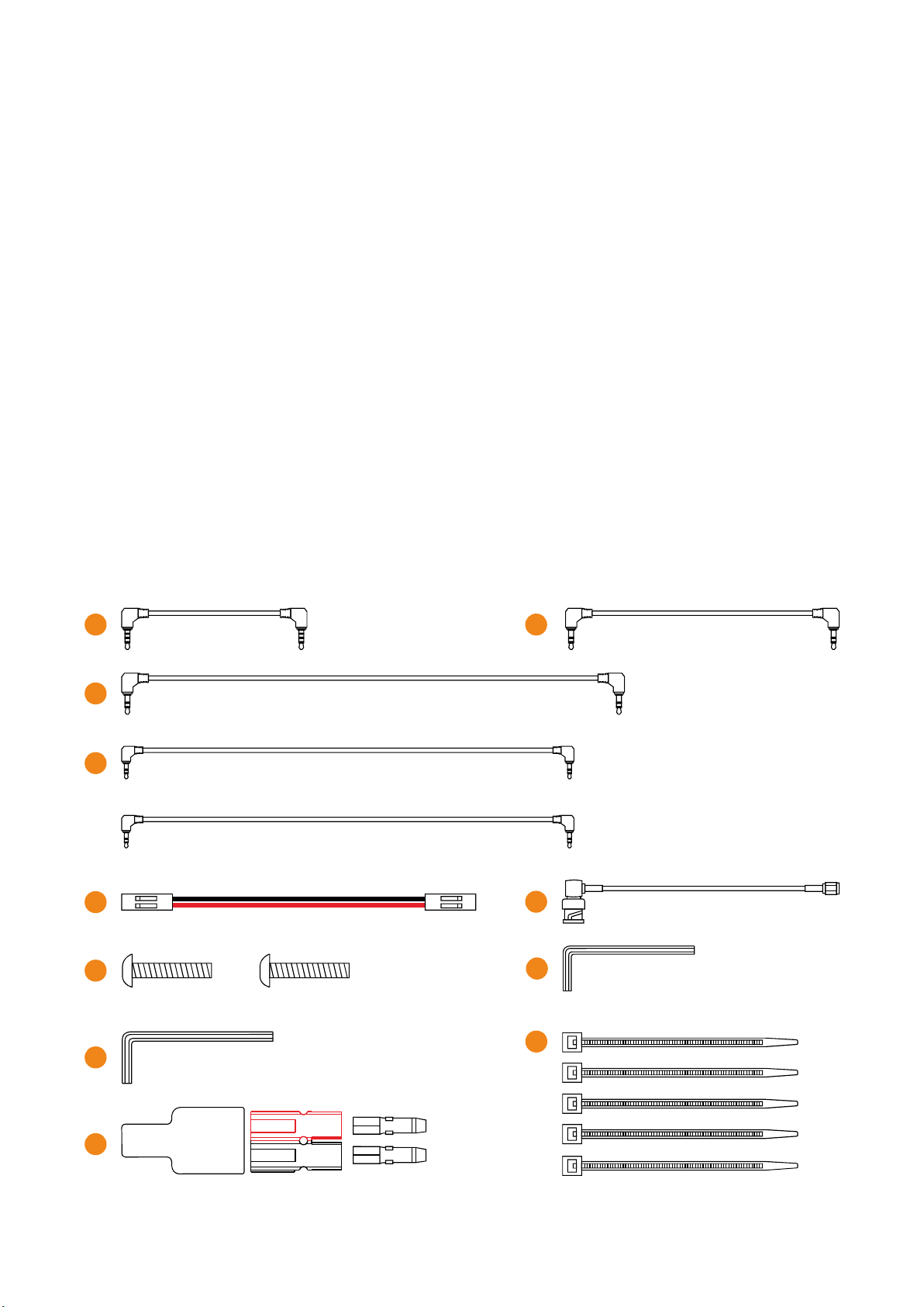
1. All the structural parts are pre-assembled when the box is delivered. Please disassemble
the related parts before installation. Specifically, it refers to the four aluminum alloy
accessories numbered as PART1, PART2, PART3 and PART4. Each part requires different type of
screws and related notes are given and please do not mix them up.
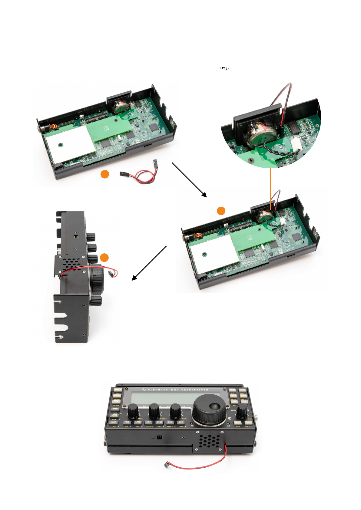
2. WINDCAMP X3 Li-ion Battery Box could be installed inside the KX3 Safety Box and related
components are available. For the installation of X3 Li-ion Battery Box and KX3
transceiver,please refer to the installation manual of X3 Li-ion Battery Box.
Introduction of the Panel functions:
1
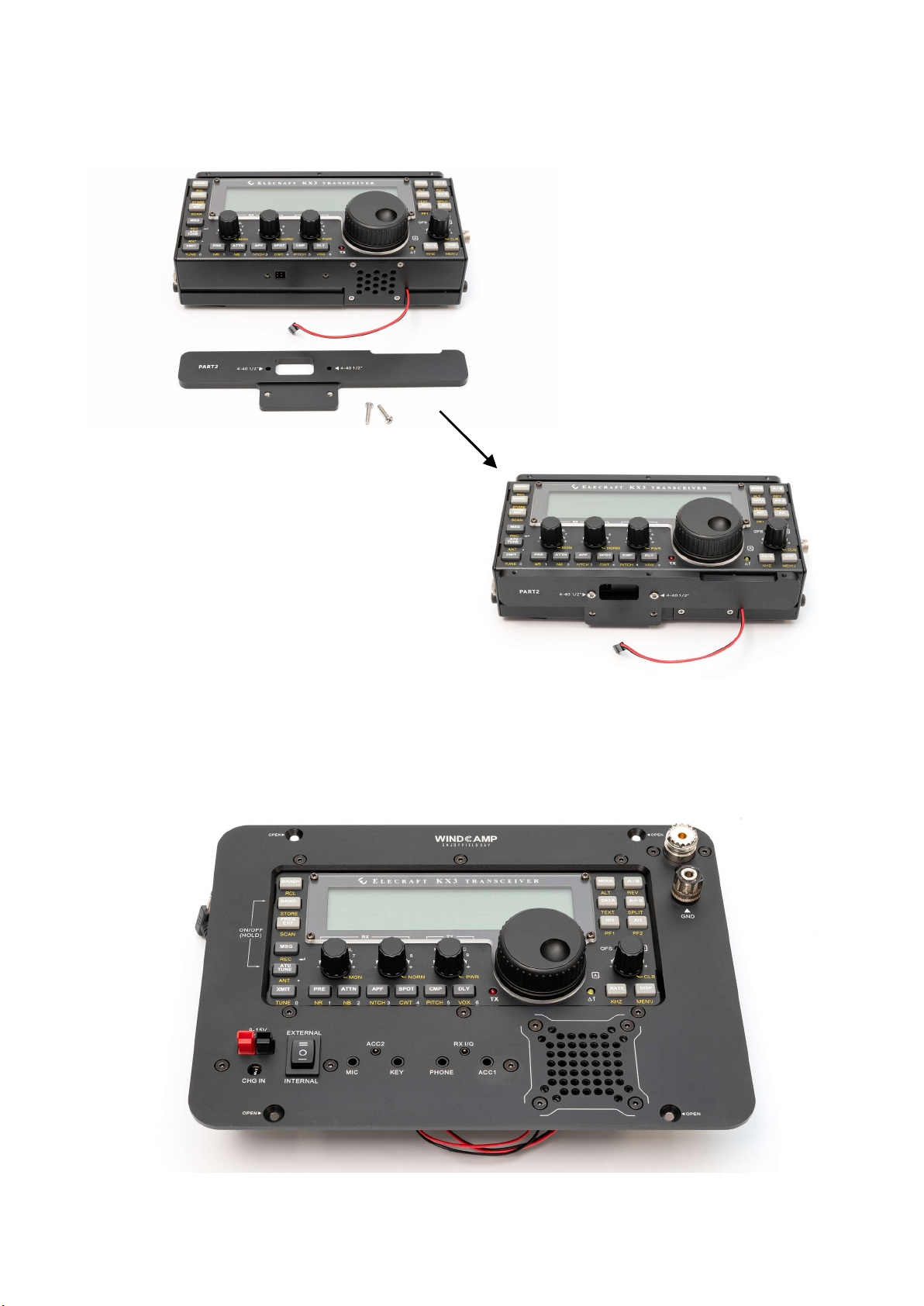
1. External protective case.
2. KX3 transceiver after installation.
3. External power supply. When there is no built-in battery or the built-in battery is
exhausted, an external power source can be connected to power the station.
4. Charging port of X3 Li-ion Battery Box. When the X3 Li-ion Battery Box is built in, please
use the matching charger for charging. If not, please use other chargers of corresponding
specifications.
5. Three-stage power switch. EXTERNAL represents the power comes from external source,
at this point the station is connected to the external power input port; INTERNAL means the
power comes from built-in battery pack, at this point the station is connected to the built-in
battery pack.The middle position means power off, at which point the station disconnects all
power ports.
6. KX3 transceiver port. MIC, KEY, PHONE, ACC, ACC2 and RX I/Q, respectively.
7. SL-16 antenna outlet.
8. Ground terminal. It can be connected to ground wire or simulated ground network.
9. Built-in Speaker
2
3
4
5
6
7
8
9
— — 1

Accessories and Functions:
1. MIC Cable, 1 Piece, length:110mm.
2. KEY Cable, 1 Piece, length:155mm.
3. ACC1 Cable, 1 Piece, length:190mm.
4. ACC2 Cable and RX Cable, 2 Pieces, length:175mm.
5. Speaker Cable, 1 Piece, length:150mm.
6. RF Connector Cable, 1 Piece, length:100mm.
7. 4-40*1/2 Screws American Standard , 2 Pieces.( )
8. Hex key (2mm), 1 Piece.
9. Hex key (2.5mm), 1 Piece.
10. AP Connector, 1 Pair(sheath is included).
11. Cable Tie, 5 Pieces, could be used inside the safety box where wire and cable need to be
bundled and managed.
1 2
3
56
78
9
10
11
— — 2
4

Installation Procedures (Excluding X3 Li-ion Battery Box) :
1. Use the M2.5mm hex key to remove the four screws inside the yellow circle. Please refers to
the following picture. And then the panel could be removed from the Safety Box. After
removing the fittings and screws, please place them properly for later use.
2. Use the M2 hex key to loose the six screws inside the yellow circle and then the internal
aluminum alloy parts of PART1, PART2, PART3 and PART4 could be removed. After removing
the fittings and screws, please place them properly for later use.
— — 3

3. Remove the thumb screws from the left and right side-plate of the KX3 transceiver, as well
as the foot frame.
4. Gently separate the two parts as if you are opening a pizza box and please disconnect the
flat cable plug once it is disassembled.
1
2
3
— — 4

5. Remove the four screws with the reference to the following picture and then remove the
radiating panel of the transceiver.
Note: If you purchased the whole set of KX3 transceiver rather than the parts package, then
there is the thermal conductivity material in between and it is difficult to separate the plate
from the machine even if the screws are removed. At this point, tools like plastic pry bar could
be used to facilitate the disassembling.
Note: The two screws in the middle of the radiator panel are longer and they are fastened
with nuts; While the screws near the edges are shorter and there is no nuts attached so it
could be fastened directly.Please mark them out to avoid mistakes when it comes to
installation.
— — 5
6. Take out PART1 aluminum alloy accessories and install the parts with reference to the
picture below.

7. Take out the speaker cable, disconnect the plug of the built-in speakers of KX3 transceiver
and connect the speaker cable instead.
Note: Please pay attention to the details when connecting and the red cable shall stay near to
the edge compared with the black one (Please see the picture).
1
2
3
— — 6
8. Stretch out the speaker cable through the gap reserved. Connecting the flat cable of the
transceiver, close the external shell and fasten the thumb-screws on both sides.

— — 7
9. Combine PART2 and the KX3 transceiver together with 2 screws (4-40*1/2, American Standard).
10. Combine the KX3 transceiver and the Safety Box panel together with 6 screws (M3*8mm, black).
Note: When doing the installation, please do not tighten the screws too hard at the beginning,
otherwise it is difficult to adjust the location. After all the screws fit in the right hole, each screw could
be tightened respectively.

11. Connect the speaker cable of the KX3 transceiver to contact pin KX3 SPK) on the circuit of Safety (
Box (see the picture below).Please pay attention to the difference between "+" and "-".
12. There is an external headset mode setting on the circuit board: when using STEREO
headphones, move the short-circuit cap to the right side and then it is the STEREO mode; When
using mono headphones, move the short circuit cap to the left side and then it is MONI mode
correspondingly.
PHONE MODE
13. Plug the KX3 DC IN power cord on the circuit board into the DC IN socket of the KX3 transceiver.
The power cord of the BATTERY could be connected to built-in battery packs that prepared by users.
— — 8

— — 9
14. There are 5 jacks(2.5mm/3.5mm) on the circuit board and they are labeled as
MIC,KEY,ACC1,ACC2 and RX I/Q respectively. Please choose the related cable and connect
them to the KX3 transceiver correspondingly.
Note: PHONE jack on KX3 transceiver does not need to be connected.
15. Connect the KX3 transceiver antenna port to the antenna port of the Safety Box panel with
the provided RF Connector Cable.
16. Place the completed panel assembly into the Safety Box and fix the panel with four
M4*8mm screws to finish the installation.
— — 9

Installation Procedures (Including X3 Li-ion Battery Box) :
1. Use the M2.5mm hex key to remove the four screws inside the yellow circle. Please refers to
the following picture. And then the panel could be removed from the Safety Box. After
removing the fittings and screws, place them properly for later use.
2. Use the M2 hex key to loose the six screws inside the yellow circle and then the internal
aluminum alloy parts of PART1, PART2, PART3 and PART4 could be removed. After removing
the fittings and screws, place them properly for later use.
— — 10

3. Remove the thumb screws from the left and right side-plate of the KX3 transceiver, as well
as the foot frame.
4. Gently separate the two parts as if you are opening a pizza box and please disconnect the
cable plug once it is disassembled.
1
2
3
— — 11

5. Remove the four screws with the reference to the following picture and then remove the
radiating panel of the transceiver.
Note: If you purchased the whole set of KX3 transceiver rather than the parts package, then
there is the thermal conductivity material in between and it is difficult to separate the plate
from the machine even if the screws are removed. At this point, tools like plastic pry bar could
be used to facilitate the disassembling.
Note: The two screws in the middle of the radiator panel are longer and they are fastened
with nuts; While the screws near the edges are shorter and there is no nuts attached so it
could be fastened directly. Please mark them out to avoid mistakes when it comes to
6. Take out PART1 aluminum alloy accessories and install the parts with reference to the
picture below.
— — 12

1
2
3
8. Stretch out the speaker cable through the gap reserved. Connecting the flat cable of the
transceiver and then close the external shell. Install the X3 Li-ion Battery Box with the
reference to its installation manual.
— — 13
7. Take out the speaker cable, disconnect the plug of the built-in speakers of KX3 transceiver
and connect the speaker cable instead.
Note: Please pay attention to the details when connecting and the red cable shall stay near to
the edge compared with the black one (Please see the picture).

10. Combine the PART3 and the PART2 together with 2 screws (M3*5mm).
11. Combine the PART4 and the PART3 together with 2 screws (M3*12mm).
Note: There is a soft cushion on the back side of PART4 and the soft cushion should be
attached to the Battery Box. The Battery Box will not move once the screws are tightened.
— — 14
9. Combine PART2 and the KX3 transceiver together with 2 screws (4-40*1/2, American
Standard).

14. There is an external headset mode setting on the circuit board: when using STEREO
headphones, move the short-circuit cap to the right side and then it is the STEREO mode;
When using mono headphones, move the short-circuit cap to the left side and then it is MONI
mode correspondingly.
PHONE MODE
— — 15
13. Connect the speaker cable of the KX3 transceiver to contact pin (KX3 SPK) on the circuit of
Safety Box (see the picture below).Please pay attention to the difference between "+" and "-".
12. Combine the KX3 transceiver and the Safety Box panel together with 6 screws (M3*8mm,
black).
Note: When doing the installation, please do not tighten the screws too hard at the
beginning, otherwise it is difficult to adjust the location. After all the screws fit in the right
hole, each screw could be tightened respectively.

15. Plug the KX3 DC IN power cord on the circuit board into the DC IN socket of the KX3
transceiver. The power cord of the BATTERY could be connected to any DC sockets on the X3
Li-ion Battery Box.
16. There are 5 jacks(2.5mm/3.5mm) on the circuit board and they are labeled as
MIC,KEY,ACC1,ACC2 and RX I/Q,respectively.Please choose the relevant cable and connect
them to the KX3 transceiver correspondingly.
Note: PHONE jack on KX3 transceiver does not need to be connected.
17. Connect the antenna port of KX3 transceiver to the antenna port of the Safety Box panel
with the provided RF Connector Cable.
— — 16

18. Place the completed panel assembly into the Safety Box and fix the panel with four
M4*8mm screws to finish the installation.
— — 17

www.windcamp.cn
Table of contents