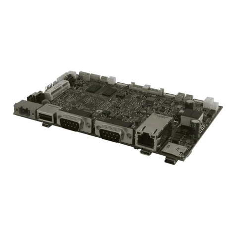
Winmate IQ30-100 User manual

Please read these instructions carefully before using this product, and save this manual for future use.
3.5” Embedded SBC IQ30V100
Qualcomm Snapdragon™ 660 octa-core, 2.2 GHz CPU
User Manual
Document Version 1.0
Document Part No. 915211101079

2 IQ30 3.5" Embedded SBC User Manual
Contents
PREFACE .............................................................................................................................................................................. 3
ABOUT THIS USER MANUAL...........................................................................................................................................................5
CHAPTER 1: INTRODUCTION ................................................................................................................................................ 6
1.1 INTRODUCTION ......................................................................................................................................................................7
1.2 FEATURES..............................................................................................................................................................................7
1.3 PACKAGE CONTENTS ...............................................................................................................................................................7
1.4 SBC SPECIFICATIONS ...............................................................................................................................................................8
1.5 FUNCTIONAL DESCRIPTION .......................................................................................................................................................9
1.6 PHYSICAL DESCRIPTION..........................................................................................................................................................10
CHAPTER 2: HARDWARE INSTALLATION ............................................................................................................................. 11
2.1 SBC COMPONENTS...............................................................................................................................................................12
2.2 CONNECTOR DESCRIPTION .....................................................................................................................................................14
2.3 CONFIGURING SERIAL PORT SETTINGS IN ANDROID OS................................................................................................................38
CHAPTER 3: WINMATE HOME MANAGER .......................................................................................................................... 40
3.1 HOW TO LOCK APPLICATIONS..................................................................................................................................................41
3.2 HOW TO UNLOCK APPLICATIONS .............................................................................................................................................43
3.3HOW TO CHANGE PASSWORD .................................................................................................................................................44
CHAPTER 4: SOFTWARE INSTALLATION .............................................................................................................................. 45
4.1 ANDROID DEBUG BRIDGE DRIVER INSTALLATION.........................................................................................................................46
4.2 INSTALLING ANDROID DEBUG BRIDGE (ADB).............................................................................................................................55
4.3 OTA UPDATE GUIDE .............................................................................................................................................................56
4.4 OS IMAGE UPDATE GUIDE .....................................................................................................................................................59
CHAPTER 5: SOFTWARE PROGRAMMING GUIDE ............................................................................................................... 60
5.1ANDROID PROGRAMMING GUIDE ............................................................................................................................................61
CHAPTER 6: TECHNICAL SUPPORT ..................................................................................................................................... 66
6.1 SOFTWARE DEVELOPER SUPPORT ............................................................................................................................................67
6.2 PROBLEM REPORT FORM .......................................................................................................................................................67

3
0BChapter 1: Introduction
Preface
Copyright Notice
No part of this document may be reproduced, copied, translated, or transmitted in any form or
by any means, electronic or mechanical, for any purpose, without the prior written permission of
the original manufacturer.
Trademark Acknowledgement
Brand and product names are trademarks or registered trademarks of their respective owners.
Disclaimer
We reserve the right to make changes, without notice, to any product, including circuits and/or
software described or contained in this manual in order to improve design and/or performance.
We assume no responsibility or liability for the use of the described product(s) conveys no
license or title under any patent, copyright, or masks work rights to these products, and make
no representations or warranties that these products are free from patent, copyright, or mask
work right infringement, unless otherwise specified. Applications that are described in this
manual are for illustration purposes only. We make no representation or guarantee that such
application will be suitable for the specified use without further testing or modification.
Warranty
Our warranty guarantees that each of its products will be free from material and workmanship
defects for a period of one year from the invoice date. If the customer discovers a defect, we will,
at his/her option, repair or replace the defective product at no charge to the customer, provide it
is returned during the warranty period of one year, with transportation charges prepaid. The
returned product must be properly packaged in its original packaging to obtain warranty service.
If the serial number and the product shipping data differ by over 30 days, the in-warranty
service will be made according to the shipping date. In the serial numbers the third and fourth
two digits give the year of manufacture, and the fifth digit means the month (e. g., with A for
October, B for November and C for December).
For example, the serial number 1W19Axxxxxxxx means October of year 2019.
Customer Service
We provide a service guide for any problem by the following steps: First, visit the website of our
distributor to find the update information about the product. Second, contact with your distributor,
sales representative, or our customer service center for technical support if you need additional
assistance.
You may need the following information ready before you call:
•Product serial number
•Software (OS, version, application software, etc.)
•Detailed description of the problem
•The exact wording of error messages
In addition, free technical support is available from our engineers every business day. We are
always ready to give advice on application requirements or specific information on the
installation and operation of any of our products.
4 IQ30 3.5" Embedded SBC User Manual
Advisory Conventions
Four types of advisories are used throughout the user manual to provide helpful information or
to alert you to the potential for hardware damage or personal injury. These are Notes, Important,
Cautions, and Warnings. The following is an example of each type of advisory.
Note:
A note is used to emphasize helpful information
Important:
An important note indicates information that is important for you to know.
Caution
A Caution alert indicates potential damage to hardware and explains how to avoid
the potential problem.
Warning!
An Electrical Shock Warning indicates the potential harm from electrical hazards
and how to avoid the potential problem.
Safety Precautions
C
aution
Always ground yourself to remove any static charge before touching the
board.
Modern electronic devices are very sensitive to static electric charges. As a
safety precaution, use a grounding wrist strap
at all times. Place all electronic
components in a static
-dissipative surface or static-shielded bag when they are
not in the chassis.
Safety and Warranty
1. Please read these safety instructions carefully.
2. Please keep this user manual for later reference.
3. Please disconnect this equipment from any AC outlet before cleaning. Do not use liquid or
spray detergents for cleaning. Use a damp cloth.
4. For pluggable equipment, the power outlet must be installed near the equipment and must
be easily accessible.
5. Keep this equipment away from humidity.
6. Put this equipment on a reliable surface during installation. Dropping it or letting it fall could
cause damage.
7. Make sure the voltage of the power source is correct before connecting the equipment to
the power outlet.
8. Position the power cord so that people cannot step on it. Do not place anything over the
power cord.
9. All cautions and warnings on the equipment should be noted.
10. If the equipment is not used for a long time, disconnect it from the power source to avoid
damage by transient over-voltage.

5
0BChapter 1: Introduction
11. If any of the following situations arises, get the equipment checked by service personnel:
A. The power cord or plug is damaged.
B. Liquid has penetrated into the equipment.
C. The equipment has been exposed to moisture.
D. The equipment does not work well, or you cannot get it to work according to the user’s
manual.
E. The equipment has been dropped and damaged.
F. The equipment has obvious signs of breakage.
About This User Manual
This user manual provides information about the IQ30 3.5” Embedded Board. The
documentation set for the IQ30 provides information for specific user needs, and includes:
•IQ30 SBC User Manual – contains detailed description on how to use the SBC, its
components and features.
Note
Some pictures in this guide are samples and can differ from actual product.
Revision History
Document Version Board Version Date Note
1.0 V100 27-Aug-2020 Initial document release.

6 IQ30 3.5" Embedded SBC User Manual
Chapter 1: Introduction
This chapter provides the IQ30 Motherboard
product overview,
describes its features and hardware specifications.

7
0BChapter 1: Introduction
1.1 Introduction
Thank you for choosing Winmate 3.5” Embedded SBC IQ30. The IQ30 is the 3.5” Embedded SBC
IQ30 based on the Qualcomm® Snapdragon™ 6 series mobile platform. Featuring compact 146 x
102 mm dimensions, the IQ30 design offers impressive I/O functionality, including 1 x COM, 2 x
USB 2.0, 1 x USB Type C, 1 x LAN ,1 x SD slot. Graphics features include support for EDP and
LVDS. It is suited for use in industrial automation, medical equipment, outdoor kiosks, in-vehicle
automation, and areas requiring small-size adoption with stable computing performance.
1.2 Features
The IQ30 Motherboard offers the following features:
•3.5" Form Factor (146 mm x 102 mm)
•Qualcomm Snapdragon™ 660 octa-core, 2.2 GHz CPU
•Integrated LVDS, eDP (Optional)
•3 GB LPDDR4 (Optional 4 GB), 32 GB eMMC
•Rear IO Supports 1 x COM, 2 x USB 2.0, 1 x USB Type C
•1 x LAN ,1 x Micro SD card slot
1.3 Package Contents
Inspect the equipment for damage. If any equipment is missing or damaged, contact us.
Standard packing list includes:
•Motherboard IQ30 •User Manual (Hardcopy) •Driver CD
* Pictures are for reference only and can differ from actual product.

8 IQ30 3.5" Embedded SBC User Manual
1.4 SBC Specifications
Model Name
IQ30-100
System
Specification
CPU
Qualcomm Snapdragon™ 660 octa-core, 2.2 GHz
Memory 3 GB LPDDR4 (Optional 4 GB base on MOQ 1K)
Storage 32 GB MLC
Operating System Android 9.0
Display
Specification
Interface 1 x LVDS (MIPI to LVDS)
RF WLAN Wi-Fi a/b/g/n/ac
BT BT 5.0
Audio Codec PM660L
Audio Interface Speaker, Line Out, MIC
I/O Connectors
Rear I/O
2 x USB 2.0 Type A
1 x Terminal Block(Optional for 12V DC Jack)
1 x Micro SD Card Slot
1 x Micro SIM Card Slot
1 x USB Type-C
1 x LAN(USB to LAN AX8817A)
1 x RS232/422/485(Full COM)
Internal I/O
2 x Backlight wafer(5V/3.3V)
1 x LVDS (DF13/FPC)
2 x DMIC (4 Pin Wafer/Per)
2 x USB 2.0 Touch (FFC Connector)
1 x GPIO for 5 key OSD (6 Pin Wafer)
1 x GPIO For Membrane (2x5 Wafer)
2 x Speaker (L/R, 2 Pin Wafer)
1 x 14 Pin DIDO (6 DI, 6 DO, GND, 5V)
1 x 4 Pin Wafer CANBus With Isolation
(CANH, CANL, 5V)(Optional)
1 x 10 Pin COM Port (Full COM RS232, 5V)
3 x USB 2.0 (2x4 Wafer/per)
1 x RTC Battery
1 x Debug Port (6 Pin Wafer)
1 x 5V output (2 Pin Wafer)
1 x 3.3V output (2 Pin Wafer)
1 x UART (TX, RX, 3.3V, GND)
1 x M.2 (PCIe Signal With USB)
1 x I2C
2 x ANT (Wi-Fi, BT)
Power
Requirements
Power Input
12 - 24V DC input
** DC 12V in only of use panel with DC 12V panel power.
Power
Consumption
3W
Mechanical
Specifications
Dimensions 3.5" Form Factor (146 mm x 102 mm)
Environment
Considerations
Operating
Temperature
-20 deg. C to 60 deg. C
Storage
Temperature
-40 deg. C to 70 deg. C
Operating
Humidity
10% to 95% (non-condensing, RH)

9
0BChapter 1: Introduction
1.5 Functional Description
IQ30-100 3.5” Embedded SBC Function Block

10 IQ30 3.5" Embedded SBC User Manual
1.6 Physical Description
IQ30 3.5” Embedded SBC Motherboard Dimensions
PCB Top Layer (Top View)
PCB Bottom Layer (Top View)
I/O Side (Front View)

11
1BChapter 2: Hardware Installation
Chapter 2: Hardware Installation
This chapter provides information on how to use jumpers and
connectors on the IQ30 Motherboard.

12 IQ30 3.5" Embedded SBC User Manual
2.1 SBC Components
This section describes the location of each of the board’s jumpers and connectors.
2.1.1 CB Connector Location
Connectors, Jumpers and switches
PCB Top Layer (Top View)

13
1BChapter 2: Hardware Installation
PCB Bottom Layer (Top View)
2.1.2 Antenna Connector Location
PCB Top Layer (Top View)

14 IQ30 3.5" Embedded SBC User Manual
2.2 Connector Description
Label
Function
Note
J10
Terminal Block
2EHDRM-03P
CN11
Light Bar #1
4p P:1.0mm SMD 180° white
CN10
Light Bar #2 4p P:1.0mm SMD 180° white
CN30 & CN37
COOLAY
Backlight
CN30: 2p P:1.25mm/SMD
CN37: 90° Hirose:DF13-2P-1.25V 180° brown
CN1
Backlight
7p P:2.0mm DIP 180°
LVDS1
Panel 10.1" & 15" 2*20p P:1.25mm SMD 180° White
EDP
1 EDP 2*15p P:1.25mm SMD 180° White
CN18
Panel 7" 40p 0.5mm
CN8
Touch 3.5"
6p 0.5mm
J12
Touch 7"
6p 0.5mm
J8
Micro SD card 81CSD03S030R/PUSH/ Gilded 30u
J9
SOM Debug Port 6p P:1.0mm SMD 180°White
J4
USB 3.0 Type C USB C TYPE*/ROHS/
SIM1
SIM Card Slot Push Type-5039600695
CN2
LTE Card ***/NASB0-S6701-TS50 SMD H:5mm
SW1
Switch HPS602-E 2Poles
CN12
DIDO 2*7p P:2.0mm DIP 180°
PANEL1
Front Panel 2*5p P:2.0mm DIP 180°
CN13 & CN14
COLAY
RFID
CN13: 4p P:1.0mm SMD 180° white
CN14: 4p P:1.0mm SMD 180° white
CN9
MCU JTAG 5p P:1.0mm SMD 180° white
5V1
5V 2p P:2.0mm DIP 180° Red
CN16
3.3V ***/2P Blue P:2.0mm***
J1
Sensor 4p P:1.0mm SMD 180° white
CN19
CAN BUS 4p P:1.0mm SMD 180°white
J11
CAN BUS Debug 1*5p P:2.0mm DIP 180°
COM1
COM Port #1 Com/Slim D-Sub Male 9p/ROHS
J7
COM Port #2 2*5p P:2.0mm DIP 180°
J3
USB2.0 #1 & #2
Connector
Conn/USB Dual A Type Female***
J5
USB2.0 #3 Wafer 2*4p P:2.0mm DIP 180°
J6 & J13 COLAY
USB2.0 #4 Wafer
J6: 2*4p P:2.0mm DIP 180°
J13: 4p P:2.0mm DIP 180°
CN15 & CN20
COLAY
OSD
CN15: 6p P:1.0mm SMD 180° white
CN20: 8p 0.5mm

15
1BChapter 2: Hardware Installation
Label
Function
Note
BT1
RTC Battery #1 ML414H-IV01E 3.3V/1mAh
BT2
RTC Battery #2 Hirose:DF13-2P-1.25V 180° brown
LAN1
LAN (With POE Option) RJ45 with LED/PoE+
CN7
AMIC 2p P:2.0mm DIP 180°
CN6
DMIC #1 4p P:1.0mm SMD 180°white
J2
DMIC #2 4p P:1.0mm SMD 180° white
CN4
Speaker (Right) 2p P:2.0mm DIP 180°
CN5
Speaker (Left) 2p P:2.0mm DIP 180°
CN3
Audio Jack 5p P:2.0mm DIP 180°
P1
WIFI AUX Antenna K88P132 RF CONN
P2
WIFI Main Antenna K88P132 RF CONN
P3
NFC Antenna K88P132 RF CONN
2.2.1 J10: Terminal Block
2.2.2 CN11: Light Bar #1
Pin
Signal Name
Description
1
DC_IN
DC Input 12V
2
DC_GND
DC GND
3
IGN_ISO
Ignition

16 IQ30 3.5" Embedded SBC User Manual
2.2.3 CN10: Light Bar #2
Pin
Signal Name
Description
1
+V5S
Light Bar Power 5V
2
LIGHT_RLED-
Light Bar #2 Red LED
3
LIGHT_GLED-
Light Bar #2 Green LED
4
LIGHT_BLED-
Light Bar #2 Blue LED
5
GND
Light Bar GND
6
GND
Light Bar GND
2.2.4 CN30 & CN37 COOLAY: Backlight
CN30
Pin
Signal Name
Description
1
V_LED-
Back Light V-
2
V_LED+
Back Light V+
3
GND
Back Light GND
4
GND
Back Light GND
CN37
Pin
Signal Name
Description
1
+V5S
Light Bar Power 5V
2
LIGHT_RLED1-
Light Bar #1 Red LED
3
LIGHT_GLED1-
Light Bar #1 Green LED
4
LIGHT_BLED1-
Light Bar #1 Blue LED
5
GND
Light Bar GND
6
GND
Light Bar GND

17
1BChapter 2: Hardware Installation
Pin
Signal Name
Description
1
V_LED-
Back Light V-
2
V_LED+
Back Light V+
3
GND
Back Light GND
4
GND
Back Light GND
2.2.5 CN1: Backlight
Pin
Signal Name
Description
1
BKLPWR
Back Light Power 12V (or 5V)
2
BKLPWR
Back Light Power 12V (or 5V)
3
BKLPWR
Back Light Power 12V (or 5V)
4
GND
Back Light GND
5
BRIGHT
Brightness Control
6
GND
Back Light GND
7
BLON_5V
BLON 5V
2.2.6 LVDS1: Panel 10.1" & 15"

18 IQ30 3.5" Embedded SBC User Manual
Pin
Signal Name
Description
Pin
Signal Name
Description
1
LCDVDD
LVDS Power
3.3V (or 5V/12V)
2
TXE0-_R
TX Even 0 V-
3
LCDVDD
LVDS Power
3.3V (or 5V/12V)
4
TXE0+_R
TX Even 0 V+
5
LCDVDD
LVDS Power
3.3V (or 5V/12V)
6
TXE1-_R
TX Even 1 V-
7
GND
LVDS GND
8
TXE1+_R
TX Even 1 V+
9
GND
LVDS GND
10
TXE2-_R
TX Even 2 V-
11
GND
LVDS GND
12
TXE2+_R
TX Even 2 V+
13
GND
LVDS GND
14
TXEC-_R
TX Even Clock V-
15
GND
LVDS GND
16
TXEC+_R
TX Even Clock
V+
17
GND
LVDS GND
18
TXE3-_R
TX Even 3 V-
19
GND
LVDS GND
20
TXE3+_R
TX Even 3 V+
21
GND
LVDS GND
22
TXO0-_R
TX Odd 0 V-
23
GND
LVDS GND
24
TXO0+_R
TX Odd 0 V+
25
GND
LVDS GND
26
TXO1-_R
TX Odd 1 V-
27
GND
LVDS GND
28
TXO1+_R
TX Odd 1 V+
29
GND
LVDS GND
30
TXO2-_R
TX Odd 2 V-
31
GND
LVDS GND
32
TXO2+_R
TX Odd 2 V+
33
GND
LVDS GND
34
TXOC-_R
TX Odd Clock V-
35
GND
LVDS GND
36
TXOC+_R
TX Odd Clock V+
37
GND
LVDS GND
38
TXO3-_R
TX Odd 3 V-
39
GND
LVDS GND
40
TXO3+_R
TX Odd 3 V+
41
NC
NC
42
NC
NC
43
NC
NC
44
NC
NC
2.2.7 EDP1: EDP

19
1BChapter 2: Hardware Installation
Pin
Signal Name
Description
Pin
Signal Name
Description
1
EDPAUXN
EDP AUX -
2
EDP_SDA_CONN
EDP SDA
3
EDPAUXP
EDP AUX +
4
EDP_SCL_CONN
EDP SCL
5
GND
EDP GND
6
GND
EDP GND
7
EDP_TX3N
EDP TX 3 -
8
+VCC_EDP_BKLT
EDP Power 12V
(or 5V)
9
EDP_TX3P
EDP TX 3 +
10
+VCC_EDP_BKLT
EDP Power 12V
(or 5V)
11
GND
EDP GND
12
EDP_HPD
EDP HPD
13
EDP_TX2N
EDP TX 2 -
14
GND
EDP GND
15
EDP_TX2P
EDP TX 2 +
16
GND
EDP GND
17
GND
EDP GND
18
GND
EDP GND
19
EDP_TX1N
EDP TX 1 -
20
GND
EDP GND
21
EDP_TX1P
EDP TX 1 +
22
LCDVDD
LVDS Power
3.3V (or 5V/12V)
23
GND
EDP GND
24
LCDVDD
LVDS Power
3.3V (or 5V/12V)
25
EDP_TX0N
EDP TX 0 -
26
LCDVDD
LVDS Power
3.3V (or 5V/12V)
27
EDP_TX0P
EDP TX 0 +
28
LCDVDD
LVDS Power
3.3V (or 5V/12V)
29
GND
EDP GND
30
+VCC_EDP_BKLT
EDP Power 12V
(or 5V)
31
GND
EDP GND
32
GND
EDP GND
33
NC
NC
34
NC
NC
2.2.8 CN18: Panel 7"

20 IQ30 3.5" Embedded SBC User Manual
Pin
Signal Name
Description
Pin
Signal Name
Description
1
VLCM_COM
VCOM 3.8V
2
LCDVDD
LVDS
Power 3.3V
(or 5V/12V)
3
LCDVDD
LVDS
Power 3.3V
(or 5V/12V)
4
NC
NC
5
LCD_RST#
RESET
6
STBYB
STBYB
7
GND
GND
8
LVDS_TX0_DN_FPC
TX 0 -
9
LVDS_TX0_DP_FPC
TX 0 +
10
GND
GND
11
LVDS_TX1_DN_FPC
TX 1 -
12
LVDS_TX1_DP_FPC
TX 1 +
13
GND
GND
14
LVDS_TX2_DN_FPC
TX 2 -
15
LVDS_TX2_DP_FPC
TX 2 +
16
GND
GND
17
LVDS_CLK_DN_FPC
TX CLK -
18
LVDS_CLK_DP_FPC
TX CLK +
19
GND
GND
20
LVDS_TX3_DN_FPC
TX 3 -
21
LVDS_TX3_DP_FPC
TX 3 +
22
GND
GND
23
NC
NC
24
NC
NC
25
GND
GND
26
NC
NC
27
DIMO
DIMO
28
SELB
SELB
29
VLCM_AVDD
AVDD 5V
30
GND
GND
31
V_LED-
LED-
32
V_LED-
LED-
33
LVDS_LR
L/R
34
LVDS_UD
U/D
35
VLCM_VGL
VGL
36
CABCEN1
CABCEN1
37
CABCEN0
CABCEN0
38
VLCM_VGH
VGH
39
V_LED+
LED+
40
V_LED+
LED+
41
GND
GND
42
GND
GND
43
GND
GND
44
GND
GND
2.2.9 CN8: Touch 3.5"
Pin
Net Name
Description
1
NC
NC
2
GND
GND
3
7_DP5_C
USB D+
4
7_DM5_C
USB D-
5
GND
GND
6
+TOUCH_PWR
VCC 5V
7
GND
GND
8
GND
GND
Table of contents
Other Winmate Motherboard manuals

Winmate
Winmate A831 User manual

Winmate
Winmate IB70 User manual

Winmate
Winmate IH32 User manual

Winmate
Winmate IB70 User manual

Winmate
Winmate IH70 User manual

Winmate
Winmate IV70 User manual

Winmate
Winmate OMIW User manual

Winmate
Winmate IF70 Mini-ITX SBC User manual

Winmate
Winmate IA70 User manual

Winmate
Winmate IV70-130 User manual

Winmate
Winmate IV70 User manual

Winmate
Winmate ID30 User manual

Winmate
Winmate ID31 User manual

Winmate
Winmate IH70 User manual

Winmate
Winmate IK70 User manual

Winmate
Winmate IP32S User manual

Winmate
Winmate A830 SBC User manual

Winmate
Winmate V270 User manual

Winmate
Winmate IA71 User manual

Winmate
Winmate IK70 User manual