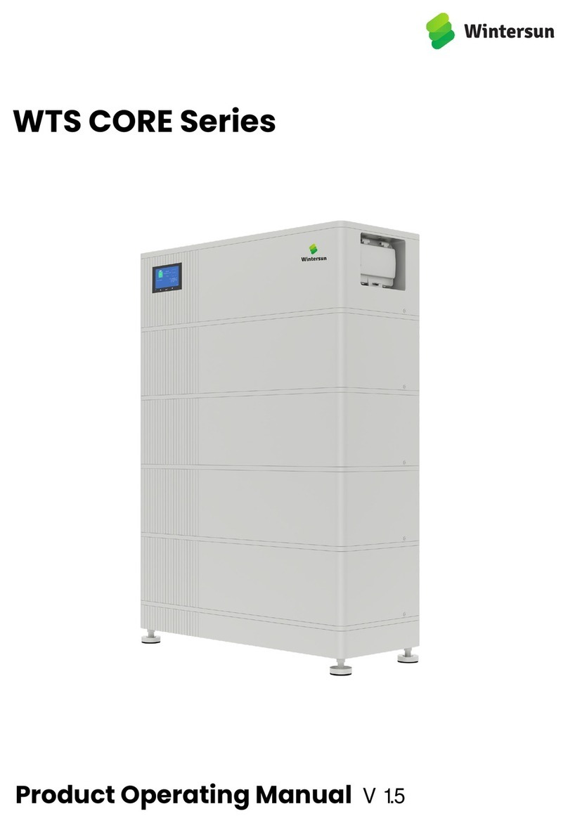
Wintersun WTS CORE Series User manual


2
Content
1. Overview................................................................................................................................................................ 3
1.1 Claim and Contact...................................................................................................................................................... 3
1.2 General Steps............................................................................................................................................................... 4
2. Error Analysis........................................................................................................................................................4
2.1 Event Code...................................................................................................................................................................... 4
2.2 No Event Codes..............................................................................................................................................................5
3. Frequently Asked Questions...........................................................................................................................6
3.1 WiFi Issues....................................................................................................................................................................... 6
3.2 Firmware Update Issue.................................................................................................................................................7
3.3 Changes in SOC............................................................................................................................................................. 7
4. Tools and Methods.............................................................................................................................................8
4.1 CORE Link+..................................................................................................................................................................... 8
4.2 Stack Exclusion Method...............................................................................................................................................8
4.3 Voltage measurement/Undervoltage....................................................................................................................10
5. Replacement Guidance.................................................................................................................................. 12
5.1 BMS Replacement....................................................................................................................................................... 12
5.2 Stack Replacement...................................................................................................................................................12
Appendix 1 Event CODE...................................................................................................................................13
Appendix 2 Ports on the BMS....................................................................................................................... 19
Appendix 3 Display on BMS...........................................................................................................................20

Service Manual V1.2
3
1. Overview
Make sure to always use the latest version of this service document, available at:
https://wintersun.de/downloads/
This manual does not replace the original manual, which can be found on https://wintersun.de/downloads/.
This manual is subject to technical revisions, and no responsibility is accepted for the accuracy of this manual.
Before
contacting
our
services
team,
please
read
this
manual
to
try
to
solve
the
problem
by
yourself.
If
the
problem
remains,
please
contact
us
ASAP.
Attention:
High
Voltage!
Improper
handling
can
cause
danger
and
damage.
Important:
The
installation
and
all
other
kinds
of
works
or
measurements
in
combination
with
the
WTS
CORE
Series
are
only
allowed
by
professional
and
qualified
personnel.
1.1
Claim
and
Contact
If,
after
completing
the
inspection
with
following
the
steps
described
in
this
manual
or
under
the
guidance
of
our
services
team,
it
is
confirmed
that
there
could
be
a
part
failure
that
needs
to
be
resolved
by
replacement,
please
register
an
account
on
our
service
website
:
https://wintersun.de
and
fill
in
the
details
on
Tickets.
If
the
appearance
of
the
battery
is
damaged,
please
take
photos
of
the
battery
and
the
packaging
on
site
and
provide
them
to
our
services
team.
The
contact
information
for
our
services
team
is
as
follows:
TEL:
+49
711
25513677
EMAIL:
service@wintersun.de

Service Manual V1.2
4
1.2 General Steps
If you find any problem with the battery, follow these steps for an initial check.
The system runs properly if :
-Inverter displays battery SOC correctly
-System charges / discharges
Note: If you can not complete the commissioning, then turn off the battery before you leave the site and make
sure the display is off. If this is not possible, remove the BMS. Please refer to 1.1 to get in touch with the
services team. After that, the blind connector of the top stack needs to be covered with an insulating
object.
2. Error Analysis
Please read 2.1 if there are event codes shown on the display, and read 2.2 if they are not available.
2.1 Event Code
After the battery system switches on, if the LED indicator turns yellow and an event code appears in the "Status
Area", please refer to Appendix 1.
No.
Inspection items
Inspection steps
1
Type of stacks
Do not mix up WTS Power-Core 1.0 and WTS Energy-Core 1.0.
2
External connections
1)Please refer to 1.3.1 to check if the wrong port is plugged in
2)Check whether the cable is loose
3)Check the cable itself for any problems.
3
Restart
NOTE: It is important that the battery is switched on before the inverter!
Else, the BMS might not start and not show any response (no display, no
WiFi).
(mind the sequence)
1) Switch off the inverter
2) Turn off the battery:Turn off the air switch on the BMS
3) Wait at least 3 minutes.
4) Turn on the battery (switch up)
5) Turn on the inverter

Service Manual V1.2
5
2.2 No Event Codes
2.2.1 System cannot be turned on
1) BMS shows no response.
If you turn on the BMS switch, but WiFi is not detected and the display does not light up, please try to restart the
system in correct sequence (refer to Step 3 in 1.2).
If the problem remains, please refer to 4.2 to check the voltage. If the voltage is normal, you can try another BMS
if available.
If the voltage is abnormal, please refer to 4.2 to identify the faulty stack.
2) Trip immediately after pulling up the air switch on BMS.
No.
Inspection items
Inspection steps
1
Wiring
1) Switch off the inverter first and then pull down the BMS switch, disconnect all
external cables and restart the battery in correct sequence.
2) If it works, check if the inverter is short-circuited; If the problem remains,
proceed with the next step.
2
Voltage
Refer to 4.3 for voltage check:
If the voltage is abnormal, identify the faulty stack by referring to 4.2.
If the voltage is normal, try another BMS if available.
2.2.2 Automatic tripping after a period of operation
Restart the system in correct order:
1. If successful:
a. If event codes appear on the LCD, please refer to Appendix 1 for more details.
b. If not, please use the app to download the logs and send them to GBA service. Repair under the guidance of
service.
(Sporadic alarms can be difficult to detect because they only occur occasionally. Therefore, it is very important to
download and make all historical battery log files available to find the root cause.)
2. If failed: Refer to 2.21.
3. LCD shows no back-light after the air switch automatically drops:
After air switch drops and the LCD dims out, please wait 2 or 3 minutes before you pull up the air switch.

Service Manual V1.2
6
3. Frequently Asked Questions
3.1 WiFi Issues
Common WiFi failures include: no WiFi signal / unstable WiFi / unable to connect to WiFi
When these failures occur, follow the steps below:
Check status of the WiFi on the LCD screen
WiFi usually turns off automatically within 5 hours after the battery turns on. Find the WiFi settings in the
"Setting. Area" on the LCD (refer to Appendix 3) and see if the status is "ON". If not, please set it as "ON". If yes,
please proceed to the next step.
Disconnect LAN cable
Remove the LAN cable during your mobile device is connecting the WiFi. After that you can connect it again to
the Internet.
Restart
To restart the WiFi, change the status of WiFi from "ON" to "OFF", and then from "OFF" to "ON".
Try other mobile devices.
Sometimes the problem comes from the mobile device itself, try to see if other mobile devices can connect to
WiFi.
Replace BMS
If none of the steps above work, please replace the BMS.

Service Manual V1.2
7
3.2 Firmware Update Issue
1) Fix WiFi
If it is caused by unstable WiFi, please refer to 3.1.
2) Restart
Restart the system in correct sequence.
3) Try again with other mobile devices.
Sometimes the problem comes from the mobile device itself, try to see if other devices can update.
4) Replace BMS
If none of the above steps work, please try another BMS if available.
3.3 Changes in SOC
1. SOC jumps
The SOC of a battery cannot be measured. It is a estimated value. In general, the state of charge (SOC) of a battery
is estimated using the voltage, but other factors such as temperature, current flow and charging behavior also play
a role. The calculation of the state of charge is generally more precise if the battery regularly sees full cycles. It is
normal to have a SOC correction / calibration every now and then.
2. SOC at commissioning
New stacks have 30% SOC upon delivery. A new BMS might show a different SOC at the beginning (mostly 50% /
30% / 0%). However, this is only to be understood as a placeholder value, as a new BMS cannot measure the SOC
of stacks. As soon as the system starts to run (charge/discharge) the SOC detection is corrected gradually. The SOC
calibration is completed after the latest full cycle

Service Manual V1.2
8
4. Tools and Methods
4.1 CORE Link+
With the CORE Link+ you can:
1) read the battery information;
2) update firmware;
3) export / download battery logs.
The CORE Link+ is constantly being improved and updated. Make sure to use the latest program version.
For the service analysis, please download and provide the data / logs as described in the program instructions .
Note: You need a Windows computer that can be linked to the battery WiFi. Login as the Installer to the CORE
Link+.
4.2 Stack Exclusion Method
Configure the battery system as that the number of stacks is minimum in a tower, 2 for WTS Power-CORE 1.0,
and 3 for WTS Energy-CORE 1.0.
1) Check the system. If Okay, add one stack at a time and check again.

Service Manual V1.2
9
......
2) If not okay: The faulty stack is probably one of the stacks in the tower. Take one of the spare stacks and
exchange with each of the remaining stacks with the spare stack one at a time. Check the battery status after each
step. If battery status turns to “OK”, the faulty stack is the one that was exchanged.

Service Manual V1.2
10
4.3 Voltage measurement/Undervoltage
4.3.1 Voltage measurement
ATTENTION: High voltage!(If the measurement position is on the same side of the battery, you need to add the
base).
You can see the max. and min. cell voltage in the CORE Link/CORE Link+. You can also get the detailed stack and
cell voltage in the CORE Link + Program or measure it manually according to the below description:
Measurement of Tower Voltage
Take down the BMS and measure the tower voltage on the top stack as shown below.
Note: The nominal voltage per stack is 86.4~116.8 V for WTS Power-CORE 1.0, and 54~73 V for WTS Energy-CORE
1.0.
If the measured voltage deviates significantly from the nominal value, please check the electrical voltage at the
individual stacks, as shown in the following section.
Measurement of Individual stack Voltage:
Positive
Negative
Measure

Service Manual V1.2
11
4.3.2.Undervoltage
A stack in which one of the cells has a voltage of <1.5 V is in undervoltage (check with CORE Link+ / CORE Link if
possible).
Stacks WTS Power-CORE 1.0 with >86.4 V and WTS Energy-CORE 1.0 with >54 V should be fine and you can
continue to check other points according to this service manual. Always make sure the version of firmware is
the latest! If the stack voltage is <116.8V (WTS Power-CORE 1.0) / <73V (WTS Energy-CORE 1.0) but the single cell
voltage is >1.5V, the battery needs to be charged as soon as possible.
If only one stack is in undervoltage: remove that one and try to start the system without it (if the remaining stacks
still comply with the Compatible Inverter List). Otherwise, make sure to avoid further discharge (e.g. remove BMS)
If more than one, or all stacks are in undervoltage: Contact the services team and make sure to avoid any further
discharge of the battery (e.g remove BMS from the system)
When contacting the service, make sure to fill the service manual completely and add the following information:
1) Serial Numbers (of the BMS and all (affected) stacks)
2) Tower voltage and individual stack voltages of all stacks (related to Serial number)
3) What was the status of the system switch on the BMS when the undervoltage (UV) Linked? (tripped or not)
If possible: Logs from the battery using CORE Link+ and displayshots showing the cell voltages and Initial Firmware
(FW) Version of the Battery when UV occurs .
Detailed description of how and why the system reached undervoltage if known. Information of when the system
was installed and commissioned and in which circumstance and when the undervoltage occurs. If the battery was
never running before: Why did it never work before, and what was the status of the battery when the battery was
left (on / off / Display).

Service Manual V1.2
12
5. Replacement Guidance
Please go through the general steps beforehand, see chapter 1.3.
5.1 BMS Replacement
1. Switch off the inverter, then switch off the battery.
2. Disconnect all cables from the BMS.
3. Replace the BMS, please do not forget to update the firmware with the CORE Link or CORE Link+.
5.2 Stack Replacement
1.The 30% SOC rule must be followed.
When adding new stacks, make sure that the SOC of all stacks in the system is 30%.
2.In the meantime you can use the battery system with the remaining stacks and a correspondingly reduced
capacity (take into account the minimum number of stacks).
3.Please note: It is important that all stacks of a battery tower have a similar state of charge (SOC) with a
tolerance of 5%. New stacks have about 30% SOC. If the remaining stacks have not yet been put into operation
(not charged/ discharged), the new stack can easily be added. Otherwise, it is basically a stack extension. In this
case, please add the new stack to the system only when the system has a SOC between 25% and 35%.
.

Manuale di servizio V 1.2
13
Appendix 1 Event CODE
Event Code (EC)
Description
Operation
1001/2001
BTVH
The total voltage is too high.
Normally,this event is together with other
event codes, and please refer to the
instructions of other codes.
If there are no other event codes, please use
CORE Link/CORE Link+ to check whether the
setting of the battery is correct. If not, please
set it correctly, if correct,please contact GBA
service.
1002/2002
BTVL
The total voltage is too low.
1003/2003
CVH
The voltage of cell is too high.
1004/2004
CVL
The voltage of cell is too low.
1005/2005
CTH_C
The temperature of cell while
charging is too high
1006/2006
CTL_C
The temperature of cell while
charging is too low.
1007/2007
CTH_D
The temperature of cell while
discharging is too high
1008/2008
CTL_D
The temperature of cell while
discharging is too low
1009/2009
OC_C
Overcurrent occurs in charging
1.Check whether the setting of the system is
correct. (if correct, go to the next step, if not,
adjust the settings)
2.Restart, if the problem remains,try another
BMS if available.

Manuale di servizio V1.2
14
Event Code (EC)
Description
Operation
1010/2010
OC_D
Overcurrent occurs in discharging
1.Check whether the setting of the system
is correct. (if correct, go to the next step; if
not, adjust the settings)
2.Check that whether there is a high-power
load starts when this fault occurs. If yes,
check whether the load power is within the
power range of the inverter:
a, Not within the power range of the
inverter, reduce the loads to ensure that
the power is within the range.
b, Within the power range of the inverter,
please also contact the inverter service; If
not, proceed to the next step.
3.Restart, if the problem remains,try
another BMS if available.
1011/2011
CUB
The cell is in a serious unbalanced
condition.
Normally,this event is together with other
event codes, and please refer to the
instructions of other codes.
1014/2014
ENV_OT
The temperature of environment
is to high
Please check whether the ambient
temperature is too high. If it's normal,
restart the battery. If the problem remains,
try another BMS if available.
1101/2101
MemF
Memory fault.
Restart, if the problem remains, try another
BMS if available.
1102/2102
VSF
Voltage sensor failed.
It is accompanied by other event codes,
please refer to other event codes.
1103/2103
TSF
Temperature sensor failed.
1104/2104
BICcomF
Multiple BIC failed
Please refer to 4.2 Stack Exclusion
Method to find the faulty modules and
replace them.
If the problem remains, try another BMS if
available

Manuale di servizio V 1.2
15
Event Code (EC)
Description
Operation
1105/2105
BVSF
Total voltage sensor
failed
Restart, if the problem remains, try another BMS if
available.
1106/2106
CSF
Current sensor failed.
Restart, if the problem remains, try another BMS if
available.
(If it's possible, observe the current value on the CORE
Link/CORE Link+ and on the inverter during charging
or discharging the battery, and record the results for
feedback to GBA service).
1107/2107
R1F
Relay 1(Anode) failed.
Restart, if the problem remains, try another BMS if
available.
1109/2109
PreCCF
Pre-charge circuit
failed
1201/2201
MSOFF
Air switch off
Wait for the screen to go off and then refer to 2.22 for
processing.
If the screen does not go out, hold up the BMS for
two minutes then put it back.
1208/2208
SCAla
Short circuit alarm
1. Check whether the setting of the system is correct
(if correct, go to the next step; if not, adjust to the
correct setting)
2. Check whether the power cable connection is
correct (if correct, proceed to the next step; if
incorrect, then connect the power cable correctly).
3. Check whether there is a high-power load starts
when this fault is reported. If yes, check whether the
load power is within the power range of the inverter:
a, Not within the power range of the inverter, reduce
the load to ensure that the power is within the range.
b, Within the power range of the inverter. Please also
contact the inverter service;
If not, proceed to the next step.
4. Restart, if the problem remains, try another BMS if
available.
1301/2301
PamInc
The parameter is
incorrect.
1.Check if the settings on the LCD are correct.
(Especially the “End System” : for a single tower , it
should be “ON”; for multiple towers, the last one
should be “ON” and the others should be “OFF ” )
2. Restart.
3. Use CORE Link/CORE Link+ to update the firmware
and restart again.
4. If the problem remains, try another BMS if
available.

Manuale di servizio V1.2
16
Event Code (EC)
Description
Operation
1302/2302
MTw_1#
The module type is abnormal
1# means that the fault occurred in stack
#1, and here it only takes as an example. It
could also be other numbers.
1. Check whether the type of Stack No.1 is
correct or not.
a. If it's incorrect, replace the
corresponding stack (refer to 4.2)
b. If it's correct, restart.
2. If the problem remains, try another BMS
if available.
1303/2303
MNInc
The number of parallel stacks is
inconsistent.
Check whether the stack numbers of
towers are the same:
If not,please adjust the stack number to
make them equal.
If they are the same, restart.If the problem
remains, try another BMS if available.
1304/2304
CANCOMF
Interior CAN communication fault.
1. Check if the settings of "End system"
and "Parallel Res" are right.
2. Check whether the communication cable
is faulty .
3. For single tower system, try another BMS
if available.
4. For multiple tower systems, separate
them into single towers, and follow the
instruction according to the event codes
on each display.If there are no event codes
on each display, but this event still remains
after combiningall the towers, check
whether the RJ 45 ports have a mechanical
damage.

Manuale di servizio V 1.2
17
Event Code (EC)
Description
Operation
1306/2306
InvComTO
Inverter communication timeout.
1.Check the Setting:
Terminal Res
The status of Terminal Res on the master
tower should be ON. (except Kostal Piko MP
Plus)
Default Set, check whether the status is set
according to the manual.
2. Check the connection
Does the inverter properly detect the
battery? Check if the inverter detects the
battery parameters (e.g SOC, battery
temperature) correctly. If not, check cabling,
especially the pin definition.
3. Restart in correct order
4. If none of the above work, try another
BMS if available.
1307/2307
IDDstF
BMS ID distribution failed
1.Check if the settings of "Endsystem" and
"ParallelRes" are right.
2.Check whether the communication cable is
faulty.
3.For single tower system, try another BMS if
available.
4.For multiple tower systems, separate them
into single towers, and follow the
instruction according to the event codes on
each display.If there are no event codes on
each display, but this event still remains after
combiningall the towers, check whether the
RJ 45 ports have a mechanical damage.

Manuale di servizio V1.2
18
Event Code (EC)
Description
Operation
1308/2308
BIC_com_F_S_#1
Single BIC failed
1# means that the fault occurred in stack #1,
and here it only takes as an example. It could
also be other numbers.
Replace the corresponding stack or the stack
above this stack (refer to 4.2) and restart.
If the problem remains, try another BMS if
available.
1309/2309
PreCF
Pre-charge failed.
1. Restart
2. If problem remains, turn off the battery and
disconnect all the power cables from the
inverter, black start through the LCD display,
check if the problem remains:
If problem remains, replace the BMS,
If problem disappears, check the power cables
connection with the inverter and the inverter.
1310/2310
UpdF_Int
The update of built-in
systems(BMS/Parameter)
failed.
1. Restart.
2. Use CORE Link/CORE Link+ to update the
firmware and restart again.
3. If the problem remains, try another BMS if
available.
1113/2113
SOHL
Cycle life fault(Low SOH or
the failure of battery cell)
Normally,this event is together with other event
codes, and please refer to the instructions of
other codes.

Manuale di servizio V 1.2
19
Appendix 2 Ports on the BMS
A. In port for the parallel connection with other tower(s).
B. Out port for the parallel connection with other tower(s).
C. Network port for connecting a router or network switch .
D. For connecting an inverter’s data cable.(CAN/RS485 protocol).
E. PE
F. DC- to inverter
G. DC+ to inverter.
Other manuals for WTS CORE Series
1
This manual suits for next models
2
Table of contents
Other Wintersun Batteries Pack manuals
Popular Batteries Pack manuals by other brands

GreenWorks
GreenWorks 2901319 Operator's manual

Ryobi
Ryobi AP4001 Operator's manual

UPOWER Ecoline
UPOWER Ecoline NauticBattery NA-12Li125BL quick start guide

Mitsubishi Electric
Mitsubishi Electric BC16 Installation, operation & maintenance manual

SOK
SOK SK12V100 manual

Sony
Sony ACC-CFR operating instructions

BYD
BYD Battery-Box LV Flex Lite operating manual

Cooper Lighting Solutions
Cooper Lighting Solutions Metalux CBRK installation instructions

SolaX Power
SolaX Power SOLAX BOX Quick installation guide

Aegis
Aegis ALF-036050A user manual

Mastervolt
Mastervolt 1603 manual

Panasonic
Panasonic CF-VZSU0PW operating instructions