Wireless Pacific X10DR ELITE User manual

User
Manual

X10DR
®
If you would like to review or print out a larger
version of this user manual on-line, then go to:
www.wirelesscorpltd.com
2
This product is designed to radiate low
levels of radio energy in accordance with
global government approved regula-
tory standards. It features Adaptive Power
Output. APO automatically adjusts the RF
power output in accordance with signal
required. This features limits and reduces
extraneous radiated radio energy. This also
helps minimize battery consumption and
extends battery shift life. Do not touch the
antenna when operational. Keep Secure
Microphone antenna 10mm (2/5”) or more
away from your body to ensure exposure
levels remain at or below the maximum
levels. Keep your body at least 20cm/8”
from external antennas connected to the
X-Ponder mobile charger unit.

Table of Contents
Parts & Functions ��������������������������������������������������� 4
Wearing the X10DR Secure Mic��������������������������� 5
Operation Description ������������������������������������������ 6
Basic Operation ���������������������������������������������������� 8
•Power On & Off, Volume Control .................. 8
•Transmitting/Receiving, Emergency.............. 8
•Talk permit tone, Charging conrmation ..... 9
•Earpiece, Out of Range, Stealth.................... 9
•Multiple unit operation.................................. 10
•Motorcycle operation................................... 11
•Headset, Covert operation .......................... 11
•Technical Notes ............................................. 12
•Battery Charging ........................................... 12
•Replacing the battery pack ........................ 13
•Re-connection............................................... 14
•Audio adjustment.......................................... 14
•Antennas ........................................................ 15
•Typical Wiring Diagram ................................ 16
•Installation & Connections ........................... 17
•Alternate Congurations .............................. 18
•Replacement Parts & Accessories .............. 27
•Approvals, Warranty & Warnings................. 30
•Important safety and handling.................... 32
•Specications................................................. 37
3

X10DR
®
Parts and functions
Volume up: adjusts speaker audio louder.
Volume down: adjusts speaker audio softer - minimum setting.
Microphone: talk in a normal strength voice about 3 to 5cm (2”).
PTT: press to talk - 3 quick beeps when pressed*. - When out of
range the unit will sound a slow beeping tone alert.
Emergency: A quick beep sounds when pressed* and then trig-
gers host radio’s emergency function. Hold down button as per
mobile radio’s emergency button operating instructions or as ad-
vised by your supplier - When out of range the unit will sound a
slow beeping tone alert when the button is pressed.
4
Secure
Wireless Microphone
X-Ponder
Mobile Charger
Antenna
Off/On
Emergency
PTT: Press-To-Talk
Volume up
Volume down
Headset connector (Optional) Earpiece jack
DC charging
Microphone
Loudspeaker
Status light
Antenna
Status light
Manual
Off/On
Charging contacts
Connector
Nomenclature
X10DR_ _-X_1
Product Name
SM = Secure Microphone
MD = X-Ponder Mobile Charger
U = Standard Model
X = Advanced 128 Bit Model
A B
C
D
A
B
C
D
DEFAULT ALTERNATE
Off/On
Emergency Volume up
Volume down
A
B
C
D

*Normal conguration - see Installation section for alternatives. **Buy separately as needed.
Wearing the X10DR Secure Mic
X10DR is designed to best perform when worn with
the antenna protruding above your shoulder.
Different types of carry clips are available including:
Standard clip (default) Replacement part No: XSMC
This is the traditional type allows the X10DR Secure Wireless Mi-
crophone to be clipped to work vests, clothing, epaulettes, etc.
For maximum performance 360º around your vehicle it is recom-
mended that it be worn in a location that allows the antenna to
protrude above you body. Rare earth magnets secure the micro-
phone in the X-ponder charging cradle.
Velcro® mount clip Replacement part No: XVMC
The Velcro mount type features a large Velcro “hook” disc on
the back of the microphone. A matching supplied Velcro “loop”
patch should be ideally sewn or pinned to the users work attire/
vest in the shoulder area to allow the antenna to protrude above
you body to ensure maximum range. Rare earth magnets secure
the microphone in the X-ponder charging cradle.
Removable clip Replacement part No: XRMC
This type has a removable larger spring belt clip which allows the
X10DR Secure Wireless Microphone to be clipped to heavier work
vests, leather clothing, thick epaulettes, etc. It locks mechani-
cally into the X-ponder charging cradle.
5
Note: Neodium, rare earth magnets, are fragile and can easily break if hit or
heavily dropped and will then need to be replaced. (Not covered by war-
ranty) Take extra care when handling them. Keep away from credit cards or
like items, that can be damaged by strong magnetic elds.
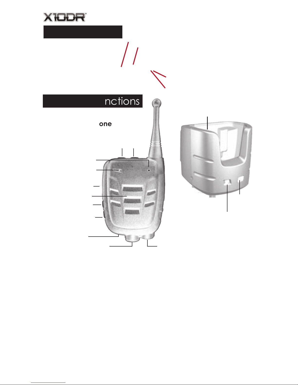
Off/On: hold for about 5 seconds to turn on or off. The Secure
mic will sound escalating or de-escalating tones to advise status.
DC charging: place into charger to automatically re-charge.
Headset connector: use with associated** headsets/accessories.
Earpiece jack: allows private listening via 3.5mm earpieces.**
Inserting the 3.5mm plug mutes the loudspeaker.
Loudspeaker: Delivers loudspeaker audio - Automatically mutes
when inserted into X-Ponder mobile charger.*
Status light: glows blue* when connected and operational.
Flashes when “out of range” or when one unit is off.
Antenna Connector: Allows connection of long range external
antenna or replacement of short range internal type.

X10DR
®
Operation Description
Congratulations on choosing the revolutionary X10DR®
Secure Wireless Microphone. Pronounced “extender”.
This incredibly compact, lightweight personal acces-
sory extends the power of the mobile radio to the palm
of your hand, whether in and out of the vehicle. X10DR
stands ready to re-dene mobile network design by in-
creasing user functionality and mobility whilst dramati-
cally improving the effectiveness of your infrastructure
investment. This visionary solution provides users out of
vehicle communications with the power and perfor-
mance of their mobile radio.
X10DR cuts the cord and for the rst time puts the mi-
crophone and radio system access into the palm of the
users hand when away from the vehicle, delivering true
mobility without system compromise. Users can feel to-
tally condent their private communications are kept
secure due to the smart 64 bit/128 bit encryption (model
dependent) functionality. X10DR uniquely incorporates
HLC™ “Hard Line Coding” connection protocol that
virtually eliminates any possibility of outside intrusion be-
tween the X10DR and your vehicle’s mobile. When the
mission is critical, X10DR delivers.
X10DR unleashes the power of your mobile radio al-
lowing wireless communication with a xed located
or vehicle radio: 60, 150, 300 metres (yards) or more.*
Our EVR™ enhanced voice resilience audio ensures us-
ers can communicate with clean clear audio, with the
power and range of their mobile radio, whilst not being
tied to the vehicle allowing the user to be truly mobile in
every operational environment.
Finally, if you go out of range, the blue LED will ash and
the unit will sound a warning tone if you press the PTT
or Emergency button so you know to move back into
your communication zone or to be simply aware. This
ability to now communicate whilst outside your vehicle
signicantly enhances a safer and more secure work
environment for everyone who carries an X10DR Secure
Wireless Microphone. 6

How it works
7
SECURE WIRELESS COMMUNICATION
via your vehicle’s mobile radio
60.... 150.... 300 Metres.

X10DR
®
Basic Operation
Power On & Off
Usually the unit will be installed such that it powers off & on with
the host mobile radio or by a manual switch tted by your instal-
lation mechanic. You can manually turn off the X-Ponder mobile
charger by pressing the front grey button for 3 seconds and the
blue LED will extinguish. You can do the same on the Secure Wire-
less Microphone by pressing the grey button. The secure mic will
sound a de-escalating tone. To power On, do the same, releas-
ing the button once the LED lights. The secure mic will sound an
escalating tone. The blue LED on both units will ash momentarily
and then go solid once they’re connected.
Volume Control
When you rst activate the unit you should rst ensure your mobile
radio’s volume is set to a comfortable listening level. You may
then adjust the Secure Wireless Microphone volume by pressing
the right top button to increase or the left to decrease. There are
5 listening levels. The minimum level is not zero but is designed so
you can still quietly hear radio trafc and not inadvertently turn
off the audio.
Transmitting/Receiving
Use like any two way radio speaker Mic i.e. press the large black
PTT button to talk and release to listen. A short Talk permit tone se-
quence will sound. Speak with a normal strong clear voice about
3-5cm (2”) from the microphone port. Do not yell as this causes
loss of clarity.
Out of Range Indication
X10DR provides the user with audible feedback should the user
move out of range from their vehicle. Note: if you walk out of
range the blue status LED will ash. If you then push the PTT an alert
tone will sound to let you know your call is not getting though.
Pressing the Emergency button when Out of Range will provide a
similar indication. Depending on your location, you may nd you
need to walk back about 10 meters (yards) closer to your vehicle
to re-connect - Blue status light will then glow solid.
8

9
Talk Permit tone
X10DR provides talk permit tones so users know when to start
speaking so that words are not lost at the start of a transmission.
If, the channel is busy, no channel grant or you are out of range,
the user will hear the X10DR talk permit tones followed by the
radio BUSY or Out of Range tone. (can be disabled by eld pro-
grammer)
Charging Conrmation Tone
X10DR provides the user with a discrete tone whenever the X10DR
Secure Mic is returned to the charging cradle. This discrete chirp
ensures the user has a positive indication that the X10DR Secure
Mic is charging and seated correctly in the cradle.
Earpiece Operation
X10DR provides the user with a weather protected 3.5mm ear-
piece jack to allow use of industry standard earpieces thereby
providing additional privacy of communications. A range of ear-
piece styles are available to suit individual user preferences. Plug-
ging in an earpiece disables the internal loudspeaker.
Emergency
If enabled, the emergency button can be used to trigger and
reset the emergency function in your suitably equipped mo-
bile radio. The time you hold the button is the time your mobile
radio sees the emergency command. So if your radio requires
you to hold the front panel emergency button for 2 secs, then
you should hold the Wireless Microphone emergency button for
2 seconds. When you press the emergency (orange) button a
short beep will sound. (Can be disabled by use of X10DR Field
programmer) See page 22 for other Emergency operations in-
formation.
Stealth Mode
For special applications the secure Mic’s Blue LED on the front of
the Secure Mic can be temporarily disabled. This is achieved by
holding down the VOLUME UP/DOWN (both) while powering up
the unit. To turn the LED back on, simply power down and power
back up. The feature may be of particular use to“Law Enforce-
ment Users” who may prefer in some situations to not be walking
around at night with a blue light glowing on their shoulder.

X10DR
®
Multiple Unit Operation
Multiple X10DR Secure Wireless Microphones with EVR™ en-
hanced audio may be connected to one radio device by use of
the optional XIB Interface box accessory. Operation is identical
to single user operation with the added benet that, each party
also hears each other talk when they transmit. This functionality
is ideal for police: where two ofcers are assigned to a patrol
van, or ambulance: where 3 paramedics can communicate at
a scene as well as with their control room. It is also ideal for ofce
use allowing a number of personnel to access a local base or
control station or remote control console while moving around a
building, shop or warehouse.
Note: communication between X10DR users is always routed
back through their respective X-ponder mobile chargers and not
direct between units. Ask your dealer for more information on this
unique and highly regarded operational capability.
INSTALLERS NOTE:
Use of the XBDA “booster” accessory is NOT compatible with
multiple unit installations. Multiple unit operation requires that an-
tennas are located ideally >50cm (20”) apart to minimize the op-
portunity for cross unit interference. Attention needs to be made
when locating antennas so that each X10DR provide similar cov-
erage patterns to ensure balanced unit to unit communications.
Motorcycle Operation
The X10DR Secure Wireless Microphone is especially suitable for
motorcycle use. Models tted with a 6 pin Hirose industrial con-
nector allow easy connection to a helmet microphone and dual
earpiece t out. Making use of the handlebar PTT input, a bike
can be congured so that, when the rider is on the bike and
presses the handle bar PTT, their headset microphone audio is
sent out over the radio. Off the bike but still wearing the helmet,
the user can press the Secure Wireless Microphone PTT to talk,.
Finally, if the user removes their helmet, they can unplug from the
Hirose connector on the base of the unit and just use the Secure
Wireless Microphone like standard.
10

The 6 pin Hirose industrial connector also allows use of a variety
of heavy duty and lightweight headsets and application specic
audio accessories to enhance you communications capabil-
ity. Use either the headset/accessory’s integral PTT or use the
speaker mic PTT to transmit. The internal speaker is immediately
disabled when a headset is plugged in.
Accessory Mic Boost
Users can increase an audio accessory’s microphone gain on
X10DR models tted with the Hirose accessory port to cater for
sensitivity requirements or variations in headset manufacturer’s
specications. To activate the higher sensitivity, the X10DR’s blue
VOLUME UP button should be held down while powering up. The
user will thereafter hear 2 short conrmation beeps at the end of
each start up tone sequence. To revert to standard operation,
the unit should be powered up with the VOLUME DOWN blue but-
ton held down.
NOTE: this does NOT effect the sensitivity of the X10DR’s normal
internal front cover microphone.
N.B. See page 36 for safety warning regarding use of headsets.
The small size of the X10DR unit may allow for its selective use
in covert applications. The remote monitor PTT function means
someone else can enable “listening” without the covert opera-
tive having to touch anything. As audio is duplex (bidirectional)
you can also talk to them at the same time allowing vital mes-
sages to be passed on even when an operative is transmitting.
The advanced model : X10DR-XX1 unit provides 128 bit encryp-
tion version to ensure high levels of voice security, while the
standard X10DR-XU1 versions provide 64 bit encryption. Both en-
cryption types are based on the well recognized highly secure
‘SAFER” format.
Headset Operation
11
Covert Operation

X10DR
®
Technical Notes
12
Battery - Charging
The X10DR Secure Wireless Microphone
should be charged overnight before
initial use. Thereafter it may be left in the
charger unit between calls, or may be
worn all day and placed back at the
end of the work day. The unit is designed
to provide about 12 hours operation be-
tween charges even on the busiest radio
channels. On quiet channels it can last
up to 3 days. When the battery does start
to go at, a short beep will sound once
every 2 minutes. It will then automatically
power down after 30 minutes, so you
should plan to re-charge the unit as soon
as is practical once the chirps are heard.
A fully discharged battery will typically re-
charge in less than 4 hours, or less if only
partially discharged. The battery will re-
charge even if the mobile charger unit
has been turned off. The microphone’s
blue status light will indicate charging
mode.
Li-POL
Please recycle thoughtfully
Simply place into pocket. The X10DR
will beep to show correct placement.
NB: do not allow debris to ll the pocket
as it may prevent the microphone from
making contact with the charging pins
Keep all liquids well away from the
charging cradle at all times.

Replacing the battery pack
When you notice the X10DR sounding a small chirp,
it indicates the battery is nearly at and should be re-
charged. The unit will self power down after 30 minutes
when voltage drops to that level. When you notice this
occurring far more often than usual, it may mean it is
time for the battery to be replaced.
Like all re-chargeable products, periodic replacement
of the internal battery is required. The Secure Wireless
Microphone features a 1200mA Lithium Polymer battery
to provide typically well over 12 hours operation when
used on a busy radio channel.
To maximize the life of a Lithium battery its is better to
keep it topped up by returning it to the charger often
rather than waiting for it to rst go at - which was the
opposite case with older nickel based batteries. Typical-
ly you can expect to get about 500 plus full re-charge
cycles before the battery will require replacement.
The process is simple and should only take your radio
service supplier about 5 minutes to replace and test.
Replacement of the battery should be ONLY undertak-
en by a qualied service technician so as to ensure no
damage occurs to internal circuitry and to ensure the
housing’s weatherproof integrity is not compromised.
The replacement battery part number is: XSMB-C12:
1200mA Li-Ion battery�
After replacement, the Secure Wireless Microphone
must be rst placed back into the mobile charger and
will initially should be charged for 8-10 hours prior to
commencement of use. Depending on the situation
it may also need to be “re-connected” to the mobile
charging unit)
13

X10DR
®
Re-connection
Each X10DR Secure Wireless Microphone is uniquely
connected to a specic X-Ponder mobile charger. This
ensures that all communications between the two units
are secure and cannot be compromised or interfered
with by a third party. In the event of a Secure Wireless
Microphone being lost, it can be permanently discon-
nected from the X-Ponder mobile charger by connect-
ing with a new replacement Secure Mic unit.
How to re-connect: hold the speaker mic while pressing
both the blue up and down volume controls until the
blue LED ashes and the speaker mic beeps.(after 8 secs.)
Press blue buttons
together until LED
ashes and unit
beeps
Now place the speaker mic back
into the mobile charger. After a few
seconds the speaker mic will sound a
conrmation two tone and the blue
LED on both units will glow solid to in-
dicate connection is complete.
Audio adjustments
The Secure Wireless Microphone sys-
tem is usually factory set for standard
audio levels required to provide sat-
isfactory mobile radio voice levels.
Should the volume be too soft or
loud and distorted, it may require re-
adjustment to set the correct level
for your particular installation.
Using a radio systems analyser to monitor the radio
channel adjust the internal trim pots so as to achieve
maximum permitted voice deviation within minimum
voice clipping (distortion). See Page 16 for adjustment points.
Qualied service personnel only!
14
VR1
- Tx
VR2 - Rx

As compared to the basic internal 1/4 wave stub an-
tenna, the XMMA magnetic mount antenna provides
enhanced coverage when placed on an unobstructed
area of a vehicle’s roof and should be connected via
its low loss coax cable to the RP-SMA-F output on the
mobile charger. MAKE SURE YOU FULLY TIGHTEN!
The XMAK multipolarity antenna provides even greater
coverage in multipath - non line of sight - situations. It
should be bracket mounted onto an unobstructed area
above the vehicle’s roof line and should be connected
via the supplied low loss coax cable to the RP-SMA-F
output connector. MAKE SURE YOU FULLY TIGHTEN!
Alternatively, where approved, the XBDA bidirectional
amplier may also be installed to further enhance in-
building coverage from your vehicle. The XBDA is in-
stalled in series between the antenna and the mobile
charger using a 20cm (8”) length of RG174 coax cable
and a 5M (17’) length of LMR200 coax to ensure a maxi-
mum of 1W output to the antenna. Only qualied radio
service personnel should install a XBDA so as to ensure
the effective radiation level remain in full compliance
with regulatory requirements in your country of opera-
tion�
Warning:
In the event of a damaged or lost antenna, only original
replacements should be used so as to not compromise
the units type approval certication or performance.
The speaker microphone uses a unity gain ground inde-
pendent antenna for maximum multi-directional range.
The mobile charger output has a reverse polarity SMA
female antenna connector, as does the XBDA.
Antennas
15
Keep your body at least 20cm (8”) away
from vehicle mounted external antenna�
See page 32 for other important details.

X10DR
®
16

1� Switched B+: Used to automatically turn on/off Se-
cure Wireless Microphone if connected to host radio
switched B+ output, if not, the user should supply man-
ual on/off switch. Note: internal speaker microphone
battery will still charge when the unit is turned off.
2� External Mic Audio: Audio from the Wireless Micro-
phone that is to be transmitted over the host mobile
radios transmitter. It is factory set for approx 80mV RMS.
3� Radio Mic Lo: This is microphone audio ground.
4� Receive Audio: Receive audio from the host mobile
radio that you wish to be sent to the Wireless Micro-
phone. Ideally, it should be sourced pre-volume con-
trol but can be post, as long as the host mobile radio’s
speaker audio has been sent for comfortable listening
in the vehicle.
5� Power: connected via a 1 amp in-line fuse preferably
direct to a vehicle’s 12V battery but can be any volt-
age from about 6-16VDC. Current consumption is typi-
cally 60mA/Max current 420mA@6V. (12V = <200mA)
6� Ext� PTT: Switched ground output designed to cause
the host mobile radio to transmit.
7� Emergency: Output intended to connect to the host
mobile radio’s emergency input. It is normally provides
an active switched ground but can be congured to
be active open circuit. The time held low (or high) is the
exact time that the user presses the Emergency button.
This output could be used for other functions such as to
trigger the panic function of a car alarm system, provid-
ing it is correctly “buffered” so as to not cause damage
to the mobile charger.
8� COR/squelch/audio unmute: Input designed to moni-
tor the receive status of the host mobile radio. Ideally, it
is driven by an “audio unmute” switched ground com-
mand in the host mobile. i.e. when the radio’s speaker
unmutes to pass audio then the COR input should tog-
gle in sync.
Installation & Connections
17

X10DR
®
Alternatively, it could be driven by the radio’s un-
squelch command that factors in reception of required
correct CTCSS tones, etc. An internal dip switch caters
for active low or high inputs.
9� Ground: DC /Digital ground connection.
13� Remote PTT: This provides a remote alternative to
transmit secure microphone audio via the host mo-
bile radio. You may choose to connect to a motorbike
handle bar PTT, a hidden palm or footswitch, a wireless
PTT device, or even to an output from the host mobile
equipped to provide remote radio monitoring of the se-
cure microphones users audio. In such remote monitor-
ing cases, use of the remote PTT input causes the sensi-
tivity of the INTERNAL secure microphone to be greatly
increased, so a control room operator can more easily
monitor the health or safety of the user. There is no in-
creased audio gain when a headset is connected to
the audio port at the base of the secure microphone.
Alternate Congurations
Some alternate congurations are available by use of
the internal dip switches in the X-Ponder mobile charger
unit. These are provided to allow compatibility with dif-
ferent mobile radio types.
Re-conguration of these switches should only be
undertaken by qualied radio service personnel.
To access, rst remove the rear mounting plate from
the mobile charger. Next remove the 4 case screws to
access internal PCB. Take extreme care when handling
the PCB to prevent damage by electrostatic discharge
(ESD) or to internal wiring. Re-assemble carefully.
18

Mobile Charger PCB layout
19
# Prevents the secure mic from muting when placed inside a
charger. This option is generally recommended only when the
host radio has no internal or external speaker.
Note: may cause the re-charge time to increase signicantly on
a very busy radio channel.
Installation dip switch conguration:
- For N/C emergency trigger: Sw1 On Sw2 Off (default)
- For N/O emergency trigger: Sw1 OFF Sw2 ON
- For active low radio COR Sw3 OFF (default)
- For active high radio COR Sw3 ON
- For Vox enable Sw4 ON(default)
- For Vox disable* Sw4 OFF
- Speaker disable in cradle Sw6 ON(default)
- Speaker enable in cradle Sw6 OFF#
R40 Default: not tted - Fit 0 ohm** for DC shift COR detect
R41 Default: tted - Remove for DC shift COR detect
** or as appropriate

X10DR
®
Multiple Units
XIB Interface Box
The XIB allows multiple X10DR’s to be connected to the one mobile radio.
X10DR units can hear each others communications as well as conversations
over the network. The interface unit connects to the host radio via a XMC
series interface cable.
Each X10DR connects to the XIB by way of short 50cm (20”) XIB-CK connecting
cables. Note: Antenna placement is critical and should be ideally placed >50cm
(20”) from each other to minimize inter-unit interference. This unit is designed
to cross–connect two/three X10DR units to one host radio. The radio connects
to the RADIO port on the XIB. Units can be cascaded to allow connection of
more than three X10DRs to the one mobile.
ALIGNMENT: Before setting up the interface box, first connect each X10DR
directly one at a time to the host radio and carefully adjust VR1 & VR2 trimpots
as described on page 14. After this the X10DR units are ready to be connected
to the interface box. Next, talk on the 1st X10DR and listen to the sound coming
from the 2nd X10DR. Then talk on the 2nd X10DR and compare sound coming
from the 1st X10DR. Adjust the MAIN IN and 2ND IN trimpots so each X10DR
has the same loudness. Next, talk on the 1st X10DR and compare the host
radio transmit audio quality compared with the host radio fist microphone by
listening or another radio. If necessary adjust the RADIO OUT trimpot to match.
Finally, talk on the other radio and adjust the RADIO IN trimpot so that the re-
ceived audio on the X10DR is loud and clear, but not distorted, and matches the
audio level when talking on the other X10DR. Repeat if a third X10DR is fitted.
Note: Incorrect level settings may cause distortion or noisy audio, especially
on some digital radios.
20
Other manuals for X10DR ELITE
13
Table of contents
Other Wireless Pacific Microphone manuals

Wireless Pacific
Wireless Pacific X10DR ELITE Parts list manual

Wireless Pacific
Wireless Pacific X10DR ELITE User manual

Wireless Pacific
Wireless Pacific X10DR ELITE Owner's manual

Wireless Pacific
Wireless Pacific X10DR ELITE Owner's manual

Wireless Pacific
Wireless Pacific X10DR ELITE Operating instructions

Wireless Pacific
Wireless Pacific X10DR ELITE Assembly instructions

Wireless Pacific
Wireless Pacific X10DR Lite User manual

Wireless Pacific
Wireless Pacific X10DR CLASSIC User manual

Wireless Pacific
Wireless Pacific X10DR ELITE User manual