Code:
Issue No.
Date:
PM000PPB
03
19/11/15
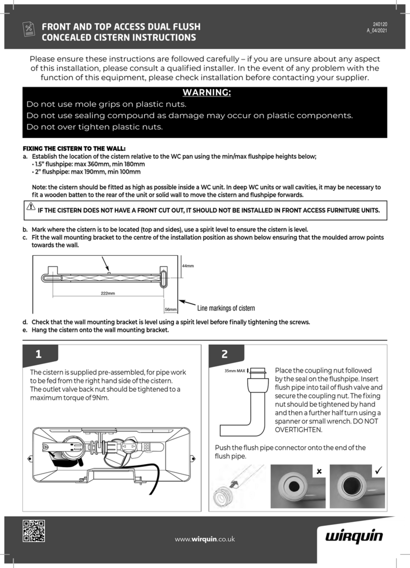
FLUSHING
1.5” Flushpipe
Place the coupling nut, follo ed by
the seal, on the flushpipe, secure
coupling nut hand tight, tighten
further if necessary, fit finned
flushpipe connector on to flushpipe,
insert into W.C. pan.
Finned flushpipe connector
2” Flushpipe
Place the coupling nut, follo ed by slip ring,
then the seal on the flushpipe, ensure the seal
has the bevelled edge pointing to ards the
end of the flushpipe, insert the flushpipe up
to the stops in the valve base then secure
coupling nut hand tight, tighten further if
necessary, fit finned flushpipe connector onto
1.5” end of flushpipe, insert into W.C. pan.
Finned flushpipe connector
Blue
Clear
HOSE
CONNECTOR
o adjust the full flush, move the slide down for more and up for
less. Part flush move the float up for less and down for more.
Always keep the part flush float 1 notch above the full flush setting.
DO NO GO BELOW SE ING 8
he overflow is adjustable from 240mm to 315mm in height. Clip
and lock the overflow 20mm above the waterline in the cistern.
Ensure the overflow is capable of discharging the incoming water.
Connect the hoses to the button, blue hose to the
end of the barrel nozzle, clear to the centre nozzle.
Make sure the hose connection is firmly on the
nozzle and in the correct order or the part flush
will not work.
2” outlet
Adjustable
overflow
Colour coded float
adjuster (grey)
Branded
top
Removable
top
1.5m air hoses
Adjustable flush
volumes (full &
part flush)
Grey top
Grey seal
1.5” and 2”
Outlet Valve
Insert threaded
section of the valve
into cistern, ith base
seal on the inside,
secure ith back-nut
hand tight, tighten
further 1/2 turn using
a spanner, check for
leaks, tighten further
if necessary.
2”
1.5”
2” or 1.5” Outlet
SLIDE
240mm
minimum
315mm
maximum
FLOA
KAYLA F ushing Va ve
Seal
Step Ring
Coupling Nut
Seal
Coupling Nut
