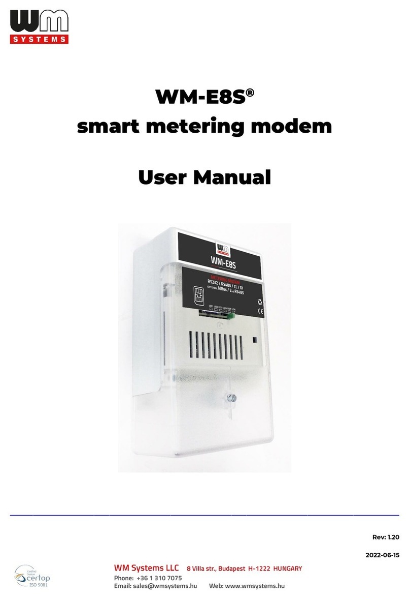
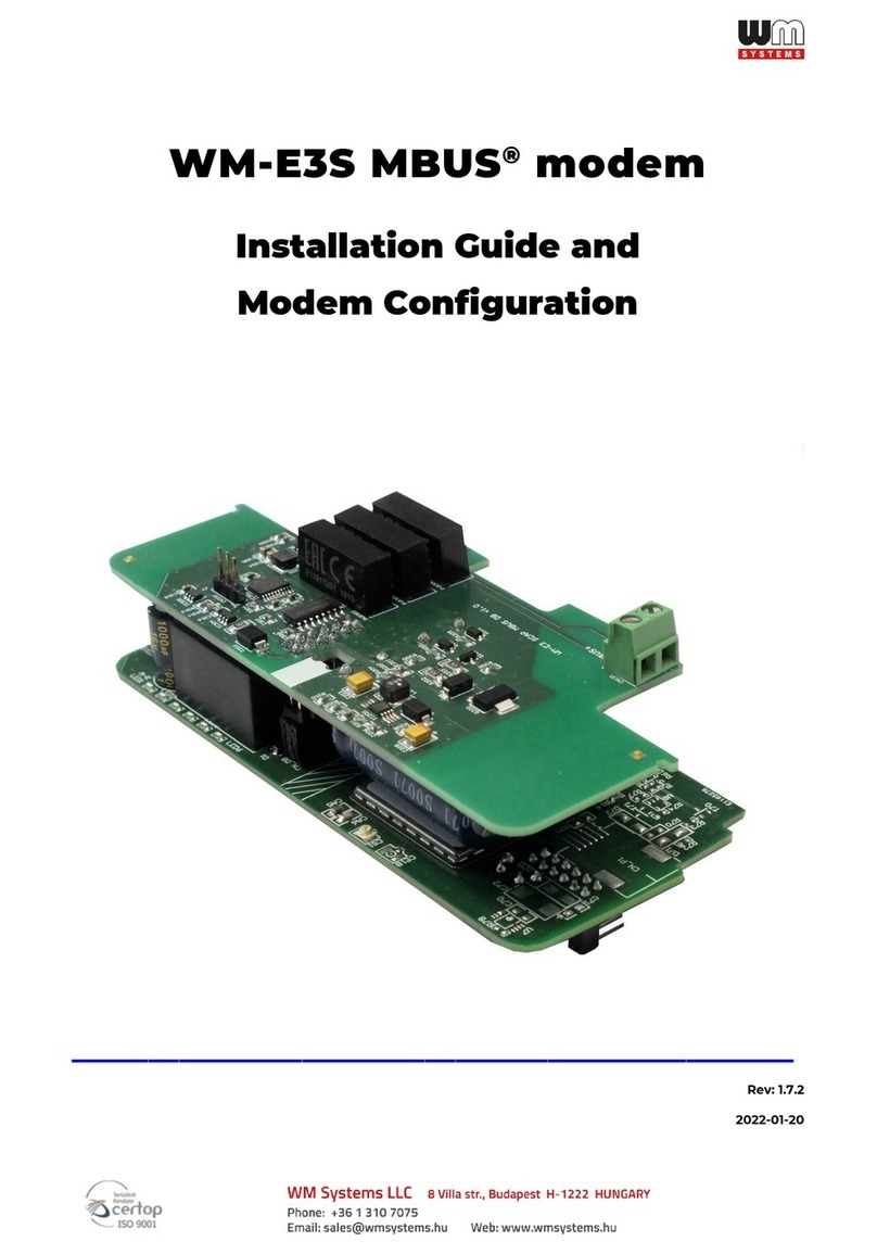
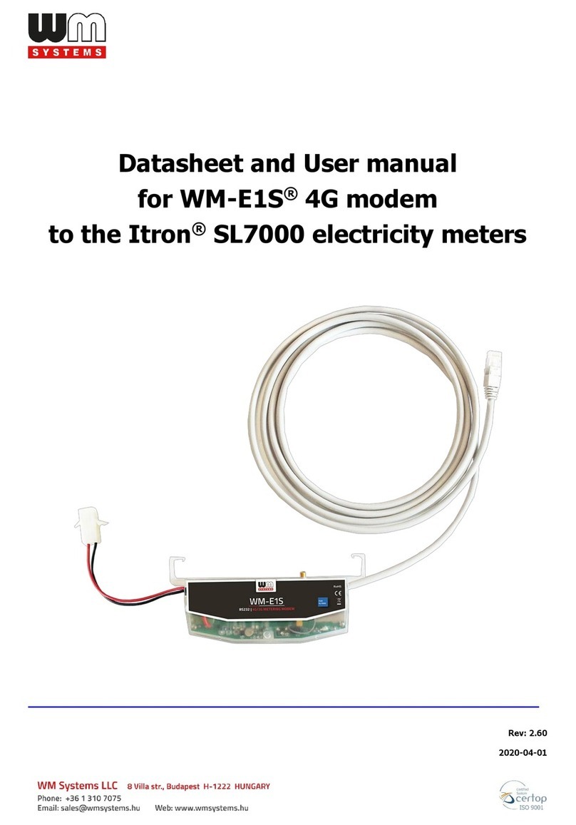
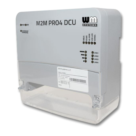
WM Systems WM-E1S User manual

Datasheet and User manual
for WM-E1S®metering modem
__________________________________________________
Rev: 2.73
2022-03-08

Document specifications
This documentation was made for presenting the installation and configuration
steps of the WM-E 1S®energy metering modem.
Document Version:
REV 2.73
Hardware Type/Version:
WM-E1S
®
modem
for the Elster
®
/ Honeywell
®
Alpha A1500, A1700, A1800, A1140/A1160
electricity meters
Hardware Version:
V 4.70
Firmware Version:
Standard version: V2.4.27
Input extender board version: V2.4.25.8B
TLS version: V2.5.52 TLS
WM-E Term®config.
software version:
V 1.3.58
Pages:
38
Status:
Final
Created:
26-09-2019
Last Modified:
08-03-2022

Chapter 1. Introduction
The WM-E1S®is a modem, which is suitable for
automated remote reading of electricity
meters remotely, on the 4G LTE-based cellular
network.
You can save money by using our modem,
because furthermore there is no need of
manual readout of the meter systems.
It can also be used as an external modem - for
a universal meter with any standard connector.
This solution also means the possibility of
future expansion, which is a great help especially in cases where the installation space
is scarce.
Using the modem can save you time and money by eliminating the need for on-site
manual reading of meters.
Wireless communication
The 4G version has 2G and 3G fallback feature, therefore in case of
outage/inaccessibility of the 4G network it is communicating further on the 2G
network.
It supports the multi-operator SIM and the roaming feature, and it is compatible with
SIM-Toolkit.
The modem has been designed to provide transparent data link from the meter to
the server.
It can be used with push data transmission method, thus the modem can initiate the
communication with the AMR centre periodically at a pre-programmed time interval
or triggered by an alarm (power outage, cover removal, reverse run, etc.)
The modem can be configured to GSM-CSD connection also - e.g. when using a 2G
module, receive the CSD calls.
The modem is independent of the mobile service provider and includes a removable
SIM card.
Your device supports multi-operator SIM cards and roaming.

Design and installation
This modem was especially developed for the 3-phase Elster®/Honeywell®A1500
Alpha, A1800 Alpha, A1140 Alpha, A1160 Alpha, A1700 Alpha type energy meters,
which can be connected to the meter by its design and its connection interface and
can be installed into the meter enclosure’s terminal cover.
Design and compatibility
The device can be also installed to the meter as an external modem –due an optional
rail-adapter (order option) - which allows to fix/mount the device.
Therefore, the modem is available with several data connectors, so it is suitable for
connecting any meter with a standard connection. In addition, it is compatible with:
- Elster®/ Honeywell®A1500 Alpha, A1800 Alpha, A1140 / A1160 Alpha, A1700 Alpha
with electricity meters
- also can be used as external, universal modem for any standard meter (with DIN
rail adapter with optional mounting)
The modem is connected to the meter via the meter's RS232 / RS485 data connector.
The device can be installed under the sealed terminal cover of the measuring service
provider, without replacing the seal certifying the first verification or the non-
destructively sealed measuring housing. For each model, the modem housing can be
ordered with a mounting tab compatible with each meter type - for proper mounting.
It can also be installed and secured as an external modem, with the help of a DIN-rail
adapter unit (which can be ordered as an option), and can be fixed to the underside
or back of the modem housing - thus securing it.
Operational characteristics
The device can be accessed remotely via the mobile network and is capable of
sending data over the Internet using an APN.
The modem is thus suitable for retrieving current and stored measurement data,
reading recorded event log and load curve data, and reading and remotely managing
meter parameter files.
The modem is basically prepared for transparent data transmission between the
metering server or metering service provider, with CSData call (only for 2G network
setting!) And via mobile internet (TCP) connection (“PULL” mode) suitable for
electricity meter registers. and remote reading of load curves, use of standard reading
commands, remote reading and modification of the meter / parameters, updating of
the meter application firmware.
Over the RS232/RS485 compatible data connection, some models have the 2-Inputs
option (for sabotage or relay/tariff switch status). In case of input line presence, the
device is able to detect the input signal changes and generating and transmitting
SMS alert notification.
Data connection
The modem can be ordered with various data connectivity options, depending on the
version:
- RS232 port (DSUB connector)
- RS485 port (2- or 4-pin ferrule connector)
- RS232 (DSUB9) and RS485 ports (2- or 4-wire socket connector)
- connector)
- RS232 and RS485 ports (RJ12 connector)
Power source and power outage
The device can be powered from the meter’s mains connection (by general 100V-240V
AC voltage).
The modem can be connected through the following modes:
a.) the meter is connected to the 57.7/100V AC power network: the modem must
be connected to line voltage (100V, L1..L2 or L2..L3 or L1..L3)
b.) the meter is connected to the 230/400V AC power network: the modem must
be connected to the phase voltage (230V, L1..N or L2..N or L3..N)
In case of the need of using external DC power, the modem can be orderd in DC-
voltage version.
Supercapacitor
The modem is also available with a power outage protection by an optional
supercapacitor component, which allows to continue the modem operation in case
of minor power outage(s).

In case of a power outage, the supercapacitors will discharge by time, and the modem
will shut down. When the power supply returns, the modem restarts and sends data
over the cellular network, and the capacitor components will be charged).
Configuration and firmware refresh
The modem can be configured locally via RS232 port, remotely with a CSData call (only
if you use a setting that also uses a 2G network!) Or via a mobile internet (TCP)
connection, and its firmware can be updated. The modem is configurable via TCP port
remotely (or via local serial connection) and operating on the wireless network by
configuring the APN, username and password (APN information is provided by your
local mobile operator).
All settings can be configured with our
administration tool (the WM-E Term®
software), but also API available so our
partner can easily adapt their current
administration environment.
The configuration is possible by one device or
for a group of devices.
The WM-E Term®tool is password protected
and user management is also possible.
The configuration tool requires Windows®platform to run. It is available in English and
some local languages as well (as French, Spanish, Czech, etc.).
Security
The product’s firmware is encrypted and prevented against to upload firmware or
data from other devices. The modem cannot be upgraded by any other 3rd party
firmware –its safe.
The control port of the modem is encrypted by AES (by option), or can be ordered with
TLS protocol usage.
The external flash- and the internal flash content of the device are encrypted.
All security protocols can be activated/deactivated by authorized client.

Expansion: 2-inputs board
The metering modem in case of need, can be ordered with a
2-inputs expansion board (with 4-pins wire and sleeve
connection).
The input can be used with sabotage detection and for status
alarm signaling (receiving the current status of the inputs).
Status and notification
The modem is continuously monitoring the mobile network and device
communication health, and can send status information (signal strength, QoS).
By the configured features, the device is able to send SMS alarm notification, Last
Gasp notification –depending on the used cellular network and mobile operators (if
the SMS notification is not disallowed on the network, then it can be used).
The LastGASP SMS notification feature is available by some models for case of
reporting the occurred possible power outages.
Certification
The modem is accomplishing with CE standard (Radio Equipment Directive
(2014/53/EU)) and safety directives (EN 60950-1) and RoHS declaration and has CE
certification.

Chapter 2. Connectors, interfaces
2.1 Modem with RS232/RS485 connector (for Honeywell®, Elster®
meters)
1
2a
3
2b
4
7
8
6
6
10
1 –Mains connector (pigtail connector, for the AC power of the meter)
2a –RS232 connector (DSUB9 - optional)
2b –RS485 connector (2-pin or 4-pin - order option, wire with sleeve)
3 –Antenna connector (SMA-M, 50 Ohm)
4 –SIM card slot (push-insert)
5 –Plastic holder (lower plastic case fixation to the upper plastic case)
6 –Plastic hooks (for mounting the modem, into the Honeywell®/ Elster®
electricity meter, under the terminal cover)
7 –Status LEDs
8 –Fixation screw of top modem enclosure
10 –U.FL antenna connector
5

2.2 Modem with RS232 connector and 2-Input add-on
The 2 inputs can be used for for sabotage detection (enclosure opening) or relay switch
detection (event push) according the next wiring:
1
2a
3
4
7
8
6
6
10
1 –Mains connector (pigtail connector for the AC power of the meter)
2a –RS232 connector (DSUB9 - optional)
3 –Antenna connector (SMA-M, 50 Ohm)
4 –SIM card slot (push-insert)
5 –Plastic holder (lower plastic case fixation to the upper plastic case)
6 –Plastic hooks to fix the modem case into the meter coverage
7 –Status LEDs
8 –Fixation screw of top modem enclosure
10 –U.FL antenna connector
11 –2 Input exansion (4-pins, wire and sleeve)
11
5

2.3 Modem with RS485 connector and 2-Input add-on
The 2 inputs can be used for for sabotage detection (enclosure opening) or relay switch
detection (event push) according the next wiring:
1
3
2b
4
7
8
6
6
10
1 –Mains connector (pigtail connector for the AC power of the meter)
2b –RS485 connector (2- or 4 pin wire with sleeve –order option)
3 –Antenna connector (SMA-M, 50 Ohm)
4 –SIM card slot (push-insert)
5 –Plastic holder (lower plastic case fixation to the upper plastic case)
6 –Plastic hooks to fix the modem case into the meter coverage
7 –Status LEDs
8 –Fixation screw of top modem enclosure
10 –U.FL antenna connector
11 –2 Input exansion (4-pins wire and sleeve)
11
5

2.4 Modem with RJ12 connector (RS232)
1
2
4
1 –Mains connector (100V AC - to the meter)
2 –RS232 connector (RJ12 –data connection modem→meter)
3 –External antenna connector (SMA-M, 50Ω)
4 –SIM card slot (mini SIM, insert-push)
5 –Plastic holder (lower plastic case fixation to the upper plastic case)
6 –Plastic hooks to fix the modem case into the meter coverage –optional
7 –Status LEDs
8 –Fixation screw of top modem enclosure
9 –DIN-rail adapter (order option) to fixate/mount to wall
6
7
5
6
9
8
3

2.6 Modem RJ12 with connection (RS485) for Honeywell®and other
type meters
1
2
4
7
5
8
3
6
6
1 –Mains connector connector (pigtail connector for the AC power of the
meter)
2 –RS485 connector (RJ12 –for data connection modem→meter)
3 –External antenna connector (SMA-M, 50Ω)
4 –SIM card slot (mini SIM, insert-push)
5 –Plastic holder (lower plastic case fixation to the upper plastic case)
6 –Plastic hooks to fix the modem case into the meter coverage –optional
7 –Status LEDs
8 –Fixation screw of top modem enclosure
12
12 –Supercapacitors (order option)

2.7 Universal metering modem with external mounting (with RJ12
connector and DIN-rail adapter mounting)
1
2
4
7
5
9
8
3
1 –Mains connector connector (pigtail connector for the AC power of the meter)
2 –RS232 (gray) or RS485 (black) connector (RJ12 data connection modem→
meter and for the configuration of the modem)
3 –External antenna connector (SMA-M, 50Ω)
4 –SIM card slot (mini SIM, insert-push)
5 –Plastic holder (lower plastic case fixation to the upper plastic case)
6 –Plastic hooks to fix the modem case into the meter coverage –optional
7 –Status LEDs
8 –Fixation screw of top modem enclosure
9 –DIN-rail adapter (order option) to fixate/mount to wall –can be glued/fixed to
the bottom side of the modem

2.8 Installation steps
Step #1: Remove the meter terminal cover (I),
loosen the screws (J).
Step #2: Ensure that the device is not powered
on, remove the AC connector (1).
Step #3: Insert a replaceable and active SIM card
(with APN) into the SIM-holder (4) - the chip looks
down, and the cutted edge of the SIM looks to the
modem. Push the SIM until it will b efastened (you will hear a click sound).
(If necessary, the SIM card can be easily removed by pressing the card again, causing
the card to be ejected from tray.)
Step #4: Insert the modem into the internal mounting points and on the meter
terminal cover (18)
attach it to the meter terminal cover according to the meter user guide.
Step #5: Mount an external magnetic base or stick antenna (12) corresponding to the
communication to the antenna connector (3).
Step #6: Connect the modem to your computer with the RS232 cable (2/2a) and an
RS232-USB converter (for RJ12 using the RJ12-USB adapter).
Attention! The modem can be programmed only through an RS232 cable!
Step #7: Connect the modem's AC power connector (1) - wire socket connection or
"pigtail" connector depending on the version - to the meter power input (for 100-230V
AC) or to an external 230V power supply.
Step #8: Configure the modem with the WM-E Term®software.
4

Step #9: After completing the configuration, remove the R232 cable (or RJ12 cable) -
labeled 2/2a - from the USB adapter.
Step #10: Disconnect the modem AC power connector (1) from the meter (or power
source). The modem will be shutting down.
Step #11: Make a data connection between the modem and the meter on the interface
you want to use (port nr. 2 / 2a - RS232 data connection, data connection 2b to the
meter RS232 data connector (G), or via RS485 port, or via the RJ12 connector (2) to the
modem's RS485 connector (D)) - according to the meter type and according to the
factory instructions.
Step #12: Install the modem according to
the meter type –e.g by placing the modem
under the the meter’s terminal cover.
For outdoor installation, install the modem
on a 35mm DIN rail (K) using a DIN rail
adapter (9) by fixing/glue the modem to the
bottom or back of the enclosure near the
meter.
Step #13: Connect the modem's AC power connector (1) - wire socket connection or
"pigtail" connector depending on the version - to the meter's power input (for 100-
230V AC). The modem starts automatically, which is also indicated by LED flashes. You
can now set the modem parameters.
Step #14: Replace the terminal cover (I) and secure with the screws (J).
Then the modem will be power supplied by the meter and the modem will start its
operation and the LED signals are signing the current activity.
9
K

2.9 Connecting the modem to the meter (Elster®/ HON®Alpha meters)
Step #1: Remove the Elster®A1500 and A1700 Alpha meter’s communication module
plastic case by releasing the 2 screws from the top of the housing.
Step #2: Connect to the meter using
the data connector.
Connect the RS485 („2b” signed cable 2-
pin wire/sleeve (brown and white wires)
to the meter’s RS485 input.
If the input has 4-pins, you can also
connect all four cables to the place
which is marked with “D”.
The picture shows the sleeve wire
connection, but the modem can also be
ordered with a “pigtail” connection.
Some meters are prepared to receive a
terminal block, in which case connect a
2- or 4-pin terminal block to the sleeves.
Wiring to Elster®/Honeywell®Alpha A1500/1700 meter
A
B
C

Step #3: Connect the modem's plastic power plug (1) to the meter's two-wire
connection (marked “E” in the following figure). If the AC power connector is not a
power plug but a wire end ferrule, connect the wires to the meter phase and ground.
E
D
F

Step #4: If you haven’t already done, connect the appropriate antenna (3) to the
modem swing connector.
Step #5: Connect the wire end sockets of the modem AC cable (1) to the meter, to the
AC power connection points (red and black wire) - carefully, because during this,
the meter can be under 100-240V AC supply voltage! Since now, the modem gets
its power from the meter.
Attention! NEVER remove the device cover when the modem is powered on!
Step #6: Attach the modem (I) under the terminal cover of the meter, to the part
designed for it (to the tabs (marked “H”), or to another attachment point.
Step #7: Replace the terminal cover (marked “I”) on the meter, slide it on, and secure
it with the screws marked “J”.
H
H
G

J
J
I

If you want to connect RS232 (labeled 2 or 2a), connect it to the RS232 socket marked
“G” on the meter.
Wiring to the Elster®/Honeywell®Alpha A1800 meter
B
D
E
F
G
Other manuals for WM-E1S
1
Table of contents
Other WM Systems Modem manuals

WM Systems
WM Systems Universal Industrial RS485 Modem User manual

WM Systems
WM Systems M2M PRO4 DCU User manual

WM Systems
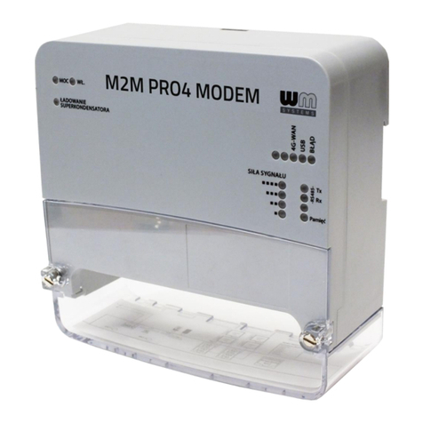
WM Systems M2M PRO4 MODEM User manual

WM Systems
WM Systems WM-E8S User manual

WM Systems
WM Systems WM-E3S 4G CI User manual

WM Systems
WM Systems WM-E2S User manual

WM Systems
WM Systems WM-E1S User manual

WM Systems
WM Systems WM-I2 User manual

WM Systems
WM Systems WM-E2S User manual

WM Systems
WM Systems M2M PRO4 MODEM User manual