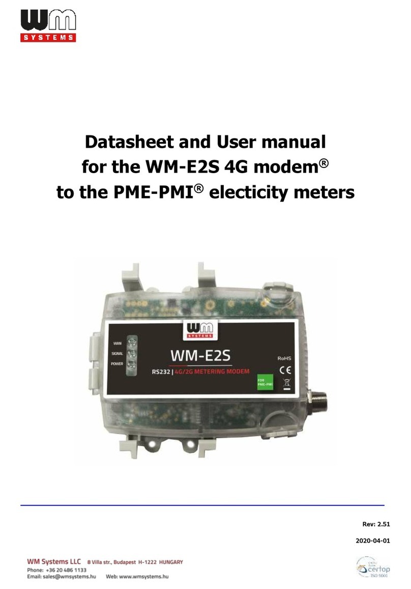
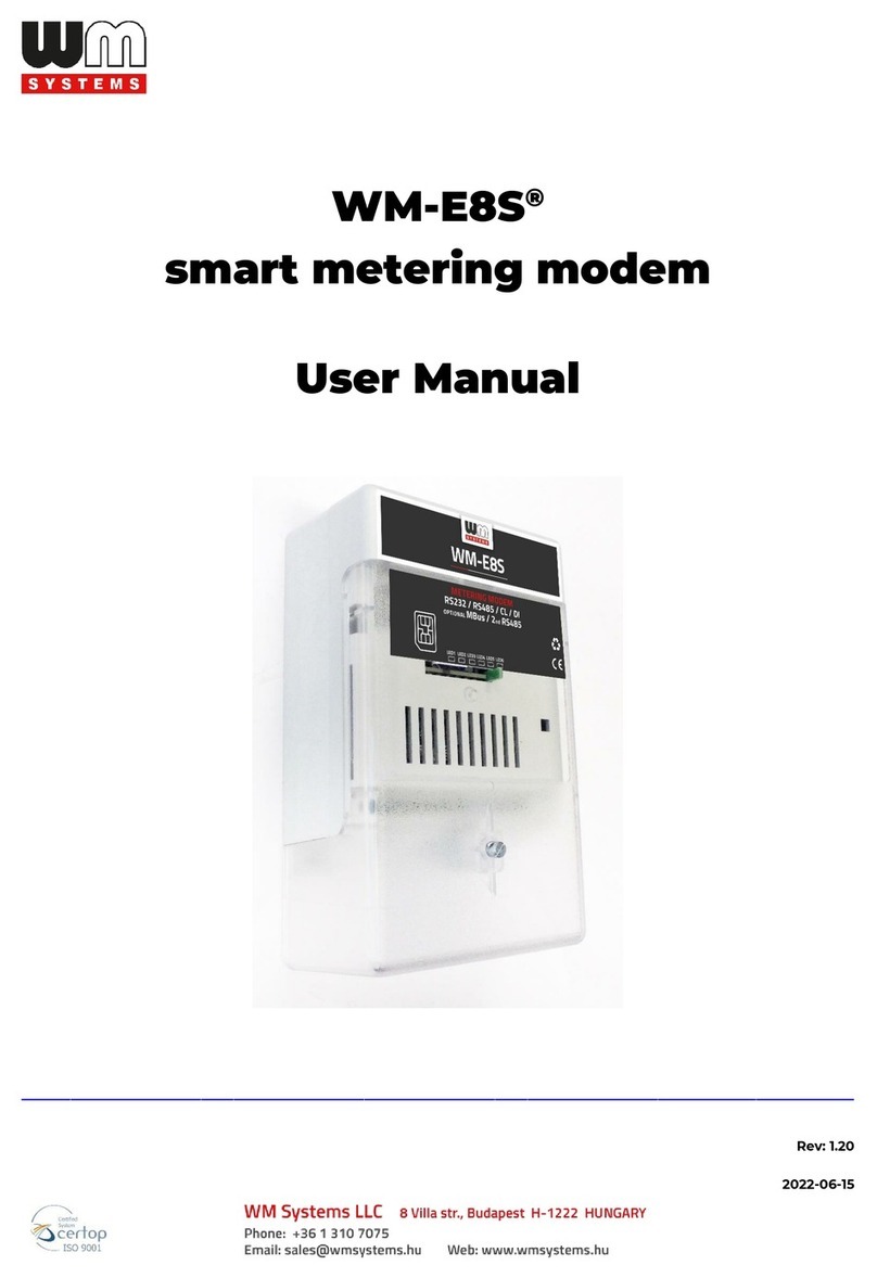
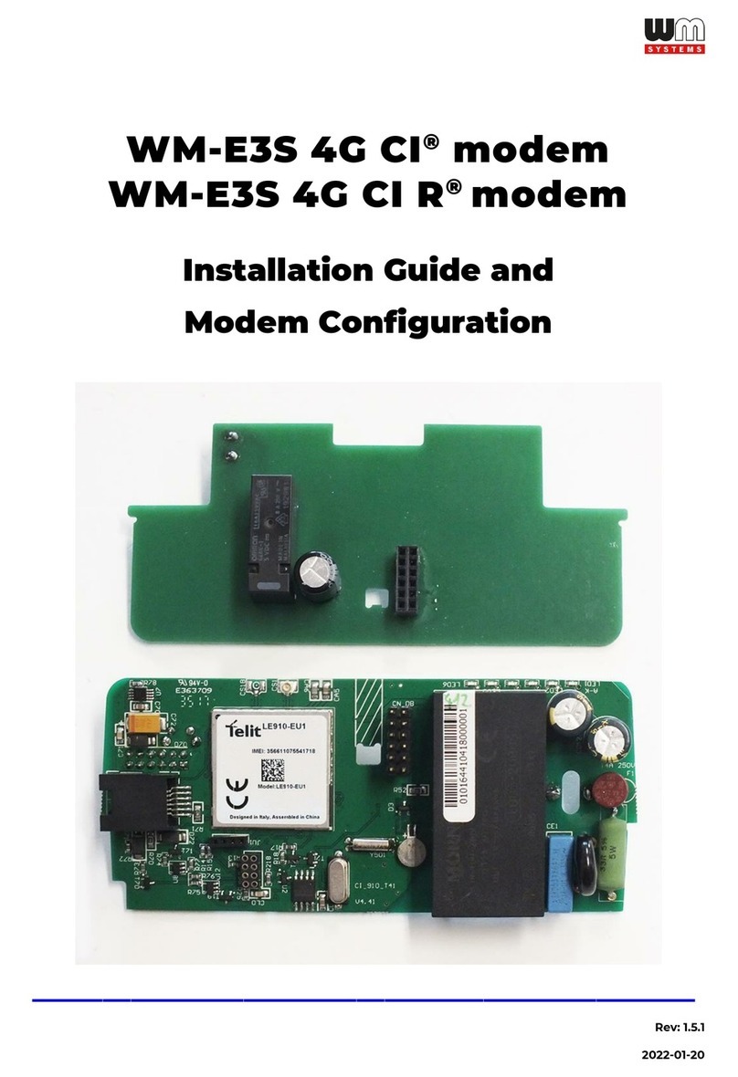
WM Systems WM-E3S User manual

WM-E3S MBUS®modem
Installation Guide and
Modem Configuration
_______________________________________________
Rev: 1.7.2
2022-01-20

2
Document specifications
Document Version:
REV 1.7.2
Hardware Type/Version:
WM-E3S MBUS
®
modem for Elster / Honeywell AS3000
/ AS3500 electricity meters, M-Bus water meters
Hardware Version
(Mainboard):
V 3.27 / V4.40
Hardware Version
(additional MBUS board):
WM-E3 SCAP MBUS DB 1.0
Firmware Version:
V 2.68
WM-E Term®config.
software version:
V 1.3.58
Pages:
27
Status:
Final
Created:
15-11-2016
Last Modified:
20-01-2022

3
Chapter 1. Introduction
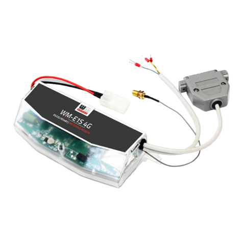
Our company develops cellular modems that work smoothly and are fully
compatible with the Honeywell / Elster electricity meters, which represent a future-
proof migration solution to the LTE network.
This modem can be readout (the measured energy consumption of the connected
electricity meters) remotely for the request of the HES center.
The modem can also read out the alarms of the meters, then push them to the
HES center by DLMS protocol.
Connection possibilities:
• 1 electricity meter to the modem
• 4 water meters (MBUS) to the modem
The water meters are readout by the modem, the consumption can be
readout in „pull” mode via DLMS protocol.
The device was designed to fit under the terminal cover of the meter and it is
compliant with the Honeywell / Elster standards.
Configuration and firmware updates can be done remotely by the WM-E Term®
software, minimizing the need for costly site visits.
Wireless communication
The modem supports the multi-operator SIM and the roaming feature, and it is
compatible with SIM-Toolkit.
The communication module is a part of the Smart Metering concept.
The device provides a SIM-card independent- and mobile operator independent
solution.
Design and compatibility
The communication module is a part of the Smart Metering concept. The modem
was especially developed for Elster®/ Honeywell®AS3000/AS3500 type electricity
meters, but can be connected to IEC meter or M-Bus capable water meters.
4
The modem can be connected to the meter by sliding into the meter’s
communication module slot and there it can be sealed.
Thus, the modem presents a compact solution, the dimensions of the meter will
not change if a modem if fitted or not. This solution offers the possibility of future
upgrade of the electricity meter with a communication module and is ideal for
installations where there is restricted assembling space.
Operation properties, features
The modem is suitable for readout and send the meter’s actual and stored
consumption values, access the recorded event log, read the load profile data. Able
to read or modify the parameter set of the meter device - remotely. It can be
accessed remotely through the cellular network (by the Telit®module) and it is able
to send data on the Internet by using an APN.
Power source and power outage
The modem is powered by 230V AC power through the meter’s integrated mains
connector.

5
Supercapacitor
The device is equipped with supercapacitors, which are preventing the
intermittent power cuts and help decrease power peaks. It is enabling to keep the
module in operation during small power outages (for max. 2 minutes).
Configuration
The modem is configurable via TCP/UDP port remotely (or via local serial
connection) and operating on the
wireless network by configuring the APN,
username and password (APN
information is provided by your local
mobile operator).
All settings can be configured with our
administration tool - the WM-E Term®
software - but also API available so our
partner can easily adapt their current administration environment.
. The configuration is possible for singular or multiply devices. The WM-E Term®
software is password protected and user management is also possible. The
multilingual configuration tool requires Windows®platform to be executed.
Firmware refresh
The WM-E Term®also provides safe firmware change for one or group of devices –
by locally or remotely.
Certification
The modem is accomplishing with CE standard (Radio Equipment Directive
(2014/53/EU)) and safety directives (EN 60950-1) and RoHS declaration.

6
Chapter 2. Connections
2.1 Interface connectors, internal connections (mainboard)
1
2
3
4
1 –Mains connector
2 –Push button
3 –ATP connector (to the meter)
4 –SIM card socket (push-insert,
mini SIM card, type 2FF)
5 –6pcs Status LEDs
6 –SMA antenna connector
5
7 –U.FL antenna connector
8 –Telit wireless module
9 –Rechargeable battery (for RTC clock)
10 –Power adapter unit
11 –Optional RJ12 interface Customer Interface
connector (6P6C) –by order request
12 –Data connector (for M-Bus expansion board)
6
7
8
9
10
12
11

7
2.2 Interface connectors (M-Bus expansion board)
13
13 –MBUS input for meters
14 –Wired MBUS hardware support (electronic parts)
15 –Supercapacitors (against power outage)
16 –Data connector on MBUS board (for mainboard connectivity
14
15
16

8
2.3 Assembled modem (mainboard + M-Bus expansion board)
We deliver the modem as assembled product - as it is shown in the picture
2.4 Inserting a SIM card
Insert an activated SIM card into the push-insert SIM card slot (4). The SIM card is
replaceable by pushing the inserted SIM card –if it is necessary.
The SIM-cad PIN code can be configured by the WM-E Term®application.
M-Bus board
mainboard
(modem)

9
2.5 Connecting the modem the Elster® AS3000, AS3500 meter
Remove the Elster®AS3000/AS3500
meter’s communication module plastic
case by releasing the screw from the top
middle part of the housing.
Inside the communication unit’s case mount the SMA-M antenna interface
connector (6) on the housing (fix it with the SMA connector’s screw).
MODEM
ANTENNA
METER

10
Snap the modem unit (mainboard + expansion board) into the communication
module terminal’s plastic enclosure by sliding into, through the guiding rails of the
case. Insert the modem into the right orientation into the slot. Check the 12-pin
data connector (3) position –according the next picture.
Push the modem into the terminal enclosure, until you’ll hear a click sound.

11
The interface connector (3) is close to the SMA antenna connector (6) (right top
side on the picture).
At the center of the modem, you will found
two plastic hooks, which helps you at the
fixation into the enclosure. (If you want to
remove the modem, push these hooks
carefully, and it’s free to remove the module
from enclosure’s case.)
Remove the separate cover by a sharp tool, remove upwards and connect the
antenna to the SMA interface. Slide the plastic part back
Connect the communication module to the meter by sliding the modem into the
meter enclosure.
The communication interface (3) and the mains connectors (1) must be connected
to the connector pairs from the meter housing.
Check the 12-pins data connector and the power connector (2-pins) position in the
picture. You will find the same connectors’ opposite part at the bottom meter side,
which you have to connect.

12
The meter’s terminal module housing upper right edge is a rounded as a sign of
the perfect slide fit the adaptation to the meter.
After assembling, attaching the modem terminal unit and turning on the meter,
the modem will be immediately powered on, and its operation is confirmed by the
LED signals.
1
3

13
ANTENNA
MODEM

14
2.6 Antenna connection
For proper operation of the communication module it is necessary to have
appropriate cellular network signal strength.
At the locations, where the signal strength is strong it is possible to use internal
antenna, for areas with poor reception mount an external antenna (50 Ohm SMA-
M connected) to the antenna connector (6) of the device.
2.7 Status LED signals
The modem has 6 LED lights with factory default operation –which will be listed
on the next page.
The LED identifiers can be found on the PCB –from left to right the sequence
(according to the next photo) it is the following: LED title LED1 (left –“5a” signed on
the figure), LED6 (right –signed by “5f” on the figure).

15
Factory default LED signals:
LED identifier
Events
LED 1
GSM / GPRS status
•During network registration: led is active
•During network search: blinking once per second
•When connected to the network and the IP connection is
fine: flashing twice per second
•When the mobile network access technology was
changed: quick flashing will be relied:
o2G →2 flashing per second
o3G →3 flashing per second
o4G →4 flashing per second
•If no network is detected: the led will be blank
•The LED is lighting continuously during CSD call the IP
data transmission
LED 2
SIM status / SIM or PIN
failure
•When the SIM PIN is okay: led is active
•If there is no SIM detected or SIM PIN is wrong: blinking
once per second
•RSSI signal strength: led flashing according the RSSI value
(1 sec RSSI value blinking, then 1 sec delay)
oRSSI <= -98 →1flashing
oRSSI > -98 and <= -83 →2flashing
oRSSI > -83 and <= -68 →3flashing
oRSSI > -68 →4flashing
5a
5f

16
LED 3
E-meter communication
•During the transparent meter communication: flashing
twice per second.
•At finish of the transparent communication: led is blank.
•According the IEC meter status: the LED will be active.
•In case of configuring the Multi Utility mode: led will be
active or blank.
LED 4
M-Bus status
•When MBUS communication is active: flashing
•In case of no MBUS communication: inactive
LED 5
-
•not available
LED 6
Firmware status
•When the modem has been initialized: led is active
•Firmware refresh: no led change
•When the modem has been started: flashing in every 2
seconds
Over the factory default settings, the operation of the LED signals and its
sequence can be changed by the WM-E Term®configuration tool, at the Standard
Meter Interface parameter group, where you can define one of the following
functions of the leds (LED1..LED6) according the next list:
Further configurable LED status signals:
LED status
Event
Network status and
access technology
•Network registration: the LED is active
•During the network searching: flashing once per second
•When connected to the network and the IP connection is
fine: flashing twice per second
•If the cellular network access technology was changed:
signed by quick flashing according the technology by the
following:
o2G →2 flashing / second
o3G →3 flashing / second
o4G →4 flashing / second
•If there is no available network: the LED is inactive
Meter status with IEC
polling
•When the modem→meter starts the communication, the
LED is flashing once per second.
•When the meter answers to the modem during the
communication, the LED will be turned on.
•When the modem cannot communicate with the meter
permanently, the LED will be turned off.
AMM (IEC) client state
•By default, or in case of finishing the communication of the
modem→EI client the LED is turned off
•During the modem→ EI client ** connection build-up the
LED flashing shortly once in every second
•The EI client** at login requrest –flashing once per second
•The EI client**→modem communication was built–the
LED is active
**The EI client is the transparent TCP channel from the modem to the EI server

17
2.8 MBUS connection
There are two modes of connecting MBUS
meters to the modem (currently max. 2 MBUS
capable water meters). You cannot use the
two type of MBUS connection in the same
time, therefore choose one wiring mode of the
following options, please.
Option a)
There is an MBUS input connector (13) on the modem’s MBUS expansion part.
By using this interface –according to the PCB printed wiring polarity –connect the
external meter to this interface
Option b)
You can use the MBUS capable electricity meter’s
auxiliary terminal block for connecting MBUS
meters. This is connected through the modem’s
internal data connection (12). Check the proper
wiring polarity in the meter’s user manual.
2.9 Push button
The modem has a push button (2). After assembling the modem into the meter’s
enclosure, you can use the external button to adjust.
When using the button:
-
by short pushing: the wireless network signal strength will be signed on
the LEDs 1-4 (more LED signals meaning better signal)
-
by longer pushing (for 3-5 seconds) –until all the 6 LEDs will be blinking
once: the used network technology will be signed by the following:
oLED2 will be active: when 2G network is used
oLED3 will be active: when 3G network is used
oLED4 will be active: when 4G network is used
oetc.
13

18
2

19
2.10 Power outage management
The LastGasp notification (SMS feature) is currently inactive –not implemented yet.
The supercapacitors are active and will provide termporary power source for the
modem, during the power outage –for max. 2 minutes.
The power outage is not signed by the LED signals.
After the recovery of the AC power source the supercapacitors will be automatically
charged –ca. 2-5 minutes is required for the full charge.
When the notification will be available, the LastGASP message settings can be
enabled by the WM-E Term®application –in the AMM (IEC) parameter group part.

20
Chapter 3. Modem Installation Guide
The communication modems can be configured by the WM-E Term®software or
the DM Set®/ AlphaSet®software which is also suitable for setup the electricity
meter through a serial connection.
The WM-E Term®tool is suitable over the communication settings to readout the
data and registers and the MBus data of connected meters.
Over the parameter settings of meter, modem and communication, you can also
test the modem communication by the configuration program.
Important!
During the configuration the modem is not connected to the meter, therefore it
cannot readout the parameter values through the meter-modem interface.
We offer to use the WM-E Term®configuration software to perform the settings
according its user manual –check the manual for settings.
For the proper communication of the modem, you have to configure at least the
APN settings of the SIM –as PIN code, APN, username and password. These all can
be configured by using the WM-E Term®software.
For the successful operation of the communication module it is necessary to have
appropriate signal strength.
3.1 Configuring the modem by WM-E Term
®
The Microsoft .NET framework runtime environment is required on your computer.
For modem configuration and testing you will need an APN/data package enabled,
active SIM-card with.
Sure, the configuration is possible without a SIM card, but in this case the modem
is performing restart periodically, and some modem features will be not available
until the SIM card is inserted (e.g. remote access).
If the modem was not supplied by power for a long time, it needs to be charged
before usage.
Table of contents
Other WM Systems Modem manuals

WM Systems
WM Systems WM-E1S User manual

WM Systems
WM Systems WM-E1S User manual

WM Systems
WM Systems WM-E2S User manual

WM Systems
WM Systems Universal Industrial RS485 Modem User manual

WM Systems
WM Systems WM-E8S User manual

WM Systems
WM Systems M2M PRO4 MODEM User manual

WM Systems
WM Systems WM-E3S 4G CI User manual

WM Systems
WM Systems WM-E2S User manual

WM Systems
WM Systems M2M PRO4 DCU User manual

WM Systems
WM Systems WM-I2 User manual