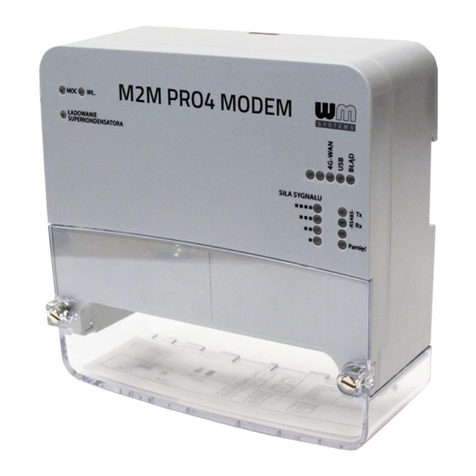
WM Systems M2M PRO4 MODEM User manual

M2M PRO4 MODEM®
User Manual
v0.92
_________________________________________
2020-02-18

Document specifications
This document was made for the M2M PRO4 MODEM®
device
and it contains the detailed
description of the configuration possibilities for the proper operation of the device.
Document category:
User Manual
Document subject:
M2M PRO4 MODEM
®
Author:
WM Systems LLC
Document version No.:
REV 0.91
Number of pages:
73
Hardware version:
BE008x
Linux Kernel:
4.14.23
OpenWRT software version:
202002071
Document status:
FINAL
Last modified:
18 February, 2020
Approval date:
18 February, 2020

Table of contents
1. DEVICE CONFIGURATION (OPENWRT USER INTERFACE) .............................. 5
1.1 Web user interface ............................................................................................................. 5
1.2 Dashboard (Main page) ..................................................................................................... 7
1.3 Menu overview .................................................................................................................. 8
1.4 Status menu ...................................................................................................................... 9
1.5 System menu .................................................................................................................... 9
1.6 Services menu .................................................................................................................. 10
1.7 Users menu ...................................................................................................................... 10
1.8 Network menu .................................................................................................................. 10
1.9 Statistics menu ................................................................................................................. 11
1.10 Logout menu .................................................................................................................. 12
2. IMPORTANT NOTES ..................................................................................... 13
3. NETWORK CONFIGURATION ........................................................................ 15
3.1 Interface settings .............................................................................................................. 15
3.2 Cellular internet settings .................................................................................................... 15
3.3 USB interface settings ....................................................................................................... 17
3.4 DHCP and DNS settings ..................................................................................................... 18
3.5 Defining route rules (Static routes)...................................................................................... 20
3.6 Firewall settings ................................................................................................................ 21
3.7 Port Forward settings ........................................................................................................ 27
3.8 NAT settings ..................................................................................................................... 28
4. ADVANCED SERVICES ................................................................................. 30
4.1 Ping IP address / checking IP ............................................................................................ 30
4.2 Network Time Service (NTP) .............................................................................................. 31
4.3 Identifiying and connecting computers ................................................................................ 33
4.4 RS485 Settings (Serial Proxy) ............................................................................................ 34
4.5 RS485 Meter connection .................................................................................................... 35
4.6 The incoming utility meter files ........................................................................................... 36
4.7 IEC scheduler .................................................................................................................... 38
4.8 Configuration of the utility meters ....................................................................................... 40
4.9 TR-069 settings ................................................................................................................ 41
4.10 LED configuration ............................................................................................................ 43
5. MAINTENANCE ........................................................................................... 46
5.1 Firmware Flashing ............................................................................................................. 46
5.2 Restarting the device.......................................................................................................... 48
5.3 Backup of device settings .................................................................................................. 49
5.4 Restore of device settings .................................................................................................. 51
5.5 Clone config backup/restore ............................................................................................... 52
6. ADMINISTRATION ....................................................................................... 54
6.1 Password change .............................................................................................................. 54
6.2 Logging ............................................................................................................................ 55
6.3 Language settings ............................................................................................................. 56
6.4 User management ............................................................................................................. 57
6.5 Periodic reboot and ping .................................................................................................... 59
6.6 Installing 3rd party applications ......................................................................................... 61
6.7 Mount points (Flash memory) ............................................................................................ 62
6.8 Statistics............................................................................................................................ 63
6.9 Startup Commands ............................................................................................................ 66
6.10 Remote access (SSH, FTP)................................................................................................ 66
6.11 Using the UCI Command Line Interface ............................................................................ 67
7. TROUBLESHOOTING ................................................................................... 69
8. SUPPORT..................................................................................................... 72
9. LEGAL NOTICE ............................................................................................ 73

1. Device configuration (OpenWrt user interface)
1.1 Web user interface
Important!
The modem software contains a pre-configured system. Please check the configuration, and if
the settings are not match with your expectations, change the configuration settings and save
them.
1. The modem’s local web user interface (LuCi®) is reachable through the USB interface –
on the device’s default addresses.
2. Enter the default web user interface address of the device on the micro USB interface is
the following URL by default: https://192.168.10.1
3. In the Mozilla browser you will get a security risk message, its not important to take care,
but choose the Advanced option.
Attention!
For accessing the web user interface we recommend to use the Mozilla Firefox®web browser.

4. Then click on the Accept the Risk and Continue button to access the modem’s webpage.
5. The OpenWRT®system’s LuCi®web interface has loaded into your browser. Now fill the
Username and Password fields and click on the Login button for the entry.
Username:
root
Password:
wmrpwdM2M

1.2 Dashboard (Main page)
After you have logged to the web interface, a startup screen appears with all relevant information
and the current status of the device.
At the System part, you can check the installed software build (M2M Software version) where
it should be
202002071
or newer. (If it has an older version, then refresh the firmware, please.)
At the Local Time you can check the current time.
The Uptime shows the spent time interval since the last bootup (or reboot).

At the Network part, first you can check the wireless modem availability at IPv4 WAN Status or
IPv6 WAN Status part, as the module’s IMEI identifier and the SIM ID identifier of the used SIM
card.
The wireless network access’ current status and health, properties can be checked at Modem RSSI
(cellular network signal strength), Network Name, Network Code and Cell ID is getting from
the mobile operator.
The modem’s wireless network address can be seen at IPv4 WAN or IPv6 status. There the Type
value will show you the connection type as
2G
,
3G
or
4G
LTE.
1.3 Menu overview
By the menu you can access the following features:

-Status –Status data, operation Logs (system, kernel, event log), Firewall, monitoring the
operation (at Processes and Realtime graphs)
-System –System settings and administration, software installation (3rd party tools), startup
settings and scheduled tasks, time synch, mount points (for Flash memory, file systems),
LED configuration, Firmware flashing, Backup/Restore of the configuration settings, Custom
commands, Reboot of the system)
-Services –RS485 metering data connection settings and configurable readout schedules.
-Users –add/delete users, Clone configuration, Periodic ping and reboot of the device
-Network –Network interface settings (USB/Wireless module), SIM PIN change, Hostname,
Bandwith Diagnostics, Diagnostics, Serial proxy (RS485 settings)
-Statistics –System graphs and statistics settings
-Logout –Logout and login with a different user
1.4 Status menu
In the Status you can check the current status (Overview).
Check system messages and event log (System Log, Kernel Log).
Check the activities of the device (Processes).
You can find monitoring features of the realtime operation at the Realtime Graphs.
You also can check or download the Event Log here.
1.5 System menu
You will found several system settings in the System and the Administration menu items.
Installation of further Software (3rd party tools, applications for the Linux distribution).
You can define the Startup applicatons.
Initialization of programs can be configured during the operation and the Scheduled Tasks.
Setup the
NTP server
for Time Synchronisation.

The Mount Points are showing the available (mounted) shares of the Linux file system and
flash memory.
The LED Configuration is also configurable for custom needs.
You also can Backup and restore your system configuration, applying Flash firmware
updates.
Custom Commands for defining some connads to execute.
Reboot menu: for restarting the device.
1.6 Users menu
You can define or modify, delete Users for allowing to access the system
Define periodic ping (for QoS check) or periodic reboot (for industrial standard or
safety reasons).
Clone config backup/restore for easy cloning of the currently saved settings to
another device.
Clone config backup/restore plane text –the same feature in uncompressed format.

1.7 Network menu
Here you can configure the settings of each network Interfaces (for the wireless module
and the USB port)
You can define the DHCP and DNS settings for the wireless LTE module and connection.
Define Hostname for the modem for easier identification of the device on your network.
At the Static Routes are also configurable (IP route settings).
Firewall settings for control and rule the incoming and outgoing, througput communication.
At the Bandwith Diagnostics item, you can configure a diagnostic address for testing the
communication health.
At the Diagnostics menu, you can check network access (ping, traceroute, nslookup).
TR-069 settings are here for configuring the TR-069 compatible remote management server
and its management settings.
Also you can configure the RS485 port settings at the Serial Proxy menu.
In the IEC scheduler menu you can configuration the utility IEC1107 compatible meters’
readout setting and the FTP transmission settings (to a remote server).
1.8 Statistics menu
Check the statistics Graphs - you can test the network operation and connection health by
the ping an IP address for the interfaces.
Here you can Setup the system Statistics

1.9 Logout menu
This menu item will allow you to log out from the OpenWrt® environment in your computer
browser.

2.
Important notes
By security reasons, we do recommend to change the web user inteface login and
password as soon as you can.
The IPv6 protocol is disabled for the LAN interfaces by default, change it if you want to
use it instead of the IPv4 protocol. Use the Network / Interfaces menu USBLAN interface
and the IPv6 relevant fields.
The DHCP service is active for all interfaces, therefore the device will giving IP addresses for
the connected devices, but the protocol which is used, configured for static IP addresses for
the ethernet interfaces. If you want to use and distribute IP addresses by DHCP, change its
protocol to DHCP client. You can change its settings in the Network / DHCP and DNS settings
menu or in the Network / Interfaces menu, USBLAN interface and DHCP section.
The Firewall service is active by default (by security reasons), therefore all communication
is disabled excluding the used ethernet, DHCP, DNS and WAN channels, web port and the
necessary services and ports for normal operation for the modem.
We recommend you to disable all ports and protocols in the firewall which you are not using
actively or which are not necessary to the connection and data transmitting by respecting
the ports which are necessary for the general operation. Use to check Status / Firewall menu
to check the data throughput and the Network / Firewall to configure new roles.
The firewall is not protecting the device against external network or DoS attacks,
if you just enable the firewall feature. For a massive and advanced safety, you have to
customize the settings by harmonized with you used current network and connection
settings.
We offer to check the network traffic on your modem frequently by the Status /
Firewall menu option to be ensured that all of your connections and active communication
channels (port number, incoming IP) are using only the wanted paths and routes and
listening the defined incoming activities and consequently occuring the estimated output
traffic.
We offer to measure your throughput data and network traffic (by minutes, hours) –
use the Status / Realtime Graphs or Statistics / Graphs and calculate the estimable
data transmitting amount according your expectations and the data limits of the used SIM
card.
The modem has 4G wireless transmission capabilities and 2G/3G fallback in case of the
unavailability of the 4G network. In this case, the device will operating on the 3G or 2G

network. When the 4G network will be available again, the device will switch back to the 4G
network. This feature is configurable for the WAN interface of the device.
If you need, you can choose dedicated wireless service type or automatic mode (using which
is accessible). Therefore you can limit your data transmitting for 2G or 3G instead of the 4G
–for example. Use the Network / Interfaces menu, WAN interface,
Edit
button and
Service Type
field.
The available APN settings will be assured by the SIM card provider mobile operator or your
mobile internet service provider. Ask them about
APN
, password,
SIM PIN
and further
necessary information for the configuration.
When configuring the SIM #1 APN or PIN settings, after the saving, the modem will not
restart its module automatically with the new settings. You need to restart the modem by
the Restart WAN button in the OpenWrt®menu at Network / Interface settings.
In case of network outage, the wireless network and cable connections, sessions will be
reconnected soon, data will be received and transmitted automatically (by the settings) as
the power source was estabilished. The RS485 data will be also able to received soon.
You can configure RS485 data speed rate betweeen 300 baud and 115 200 baud, but
please consider that max. 19 200 baud is guaranteed to receive by the device. Note, that we
offer to use 2 400 baud speed rate, which is standard for utility meter’s data readout and
can be guaranteed that it will work. With higher data speed rates some connected systems
can cause loss of characters/data in case of some models, meter types.
The utility meter readout through the RS485 port is possible only by using and connecting
IEC1107, DLMS compatible (IEC 62056-21, IEC 62056-31 supported) devices.
You have to configure the RS485 meter connection settings at the Network/IEC Scheduler
menu item.
The device has service modes by its Reset button –for stop, restart and applying the
default configuration. You will found further information in the
Installation Guide

3. Network configuration
3.1 Interface settings
The list of the available network interfaces can be found at the Network / Interfaces menu item.
The USB-LAN interface is listed for configuring and using the modem by your PC through the micro
USB connection (
usb0
interface).
The WAN interface means the wireless Internet connection (as
4g-wan
) the physical 4G module.
Modifying the interface settings
At the interfaces, at right you can modify the settings with the button.
The Stop button stops the communication on the current interface, the button
reconnects the related interface connection.
3.2 Cellular internet settings
The wireless module / cellular network settings of the modem can be configured at the Network
menu, Interfaces menu item. Open the WAN item from the interface list by the
Edit
button.
(You can also use the Network / Interfaces item –if you want to configure only the
APN
settings).

The wireless connection can be operated through the dynamic and static IP address (IPv4)
assignment also - which is provided by your mobile operator.
At the General Setup tab, you can see the current status of the interface with transmitted data
amount.
Configure the module here to the wireless internet and for the 4G LTE network connection (by the
network type you want to use) for the WAN (
ppp-4g
) interface.
The Protocol value must be
PPP-4G
, the
Wireless Network
means
the Internet module connection where you can choose a
communication band or you can leave it on default value:
4G/3G/2G
–
which means the
Auto mode
.
This mode grants the best speed and quality option on the network
and
fallback
feature (the highest cellular network service is not
available - e.g. when the 4G service is not available, the 3G or 2G fallback will be used).

If you have to use a dedicated network like 3G, 2G, etc., then choose the required network type.
Take consider, that the fallback mode will be inactive in this mode –if you choose the
4G
and it the network will be not available, there will not be provided 3G or 2G fallback (if the choosen
network is not available, the device won’t get mobile network access). For fallback always choose
the Auto mode (4G/3G/2G setting).
Here you can define the SIM #1 APN name for the Internet connection, which is necessary to use.
When you will not set any value for the
APN
, the modem will restart the modem sequentially in
every ca. 10 minutes until it is not configured properly.
Here you can define SIM card’s PIN code if it is necessary for the connection.
Note, that the PIN code which is already configured here, it cannot be seen here due to the security
rules –the characters are placed by asterix signs. Just modify the PIN if you would like to change.
Important!
If you need to change the PIN code, use the Network / SIM PIN Change menu item.
Authentication methods:
The SIM #1 PAP/CHAP username and SIM #1 PAP/CHAP password settings can be
also configured here –if it is required for the connection.
If you need dialup connection for using the Internet service at your provider, set the Dial
number value (format: *99***1# ).
Click to the Save & Apply button for saving the settings, while the device is restarting the modem
with the new settings and will connecting to the cellular network.
Then, you can check the data transmitting at the Network / Interfaces menu, when check the
WAN interface status at the Interfaces part.

The device is already connected to the cellular network, it has active data traffic and the RX
(received data), TX (transmitted data) at Packets and KB (KBytes) values are growing.
At the Advanced Settings tab you will found further settings for the wireless module.
By default we do not offer to change these settings, only if you are special requirements at operating
the mobile network communication by the modem (these are the LCP Echo settings, the Bring up
on boot and the use built-in IPv6 management parameters mainly).
If you have had changed some values here, please click upon the Save & Apply button for saving
the settings. Then the device will reconnecting the module to the mobile network.
3.3 USB settings (micro USB interface)
The modem has USB connection interface, which is provided for configuration purposes (by your
USB-connected computer), and supports alternative DC power source.

The USBLAN (
usb0
) interface settings for the PC connection can be performed by using the
Network / Interfaces menu item at the USBLAN part, where you need to choose the
button. Then choose the General Setup tab.
Here you can define Protocol
(Static address
or
DHCP client
) for getting IP address from a
connected network device.
You can define the IPv4 address of you
static
connection.
The IPv6 addresses can be also used, but by default the setting of the device it is disabled by the
IPv6 assignment length (
disabled
). You can allow this and add the IPv6 settings too.
If you have had changed some values here, please click upon the Save & Apply button for saving
the settings.

3.4 DHCP and DNS
The DHCP and DNS settings can be achieved at Network menu, DHCP and DNS item at General
Settings.
Below, at the Active DHCP Leases part you can see the list of the devices, which given their IP
addresses from the modem’s DHCP service (with the renewal
lease time
).
At the Static Leases you can add network devices by the button to be guaranteed to get
the same IP address after every leade time renewal. Define a Hostname and the valid MAC-
Address of the device and the required IPv4-Address.
Other manuals for M2M PRO4 MODEM
3
Table of contents
Other WM Systems Modem manuals

WM Systems
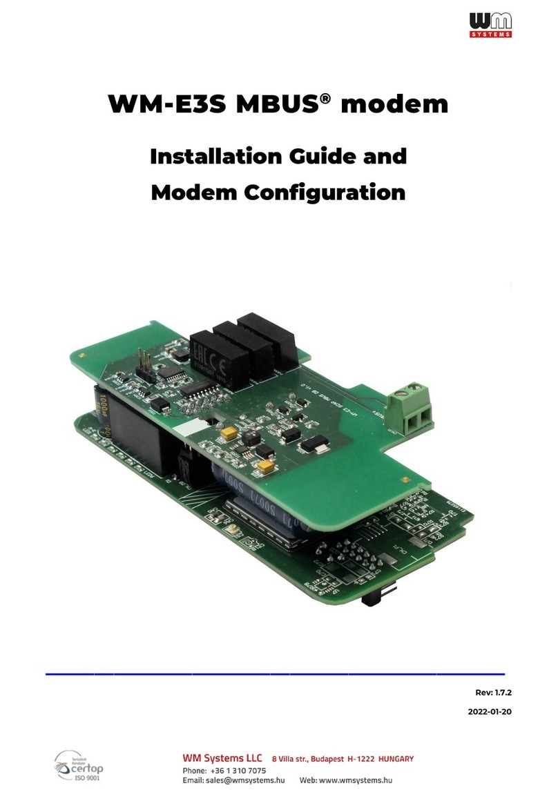
WM Systems WM-E3S User manual

WM Systems
WM Systems Universal Industrial RS485 Modem User manual

WM Systems
WM Systems WM-E1S User manual

WM Systems
WM Systems WM-E3S 4G CI User manual

WM Systems
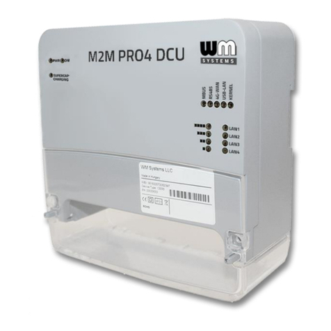
WM Systems M2M PRO4 DCU User manual

WM Systems
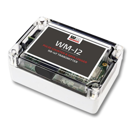
WM Systems WM-I2 User manual

WM Systems
WM Systems WM-E1S User manual

WM Systems
WM Systems M2M PRO4 MODEM User manual

WM Systems
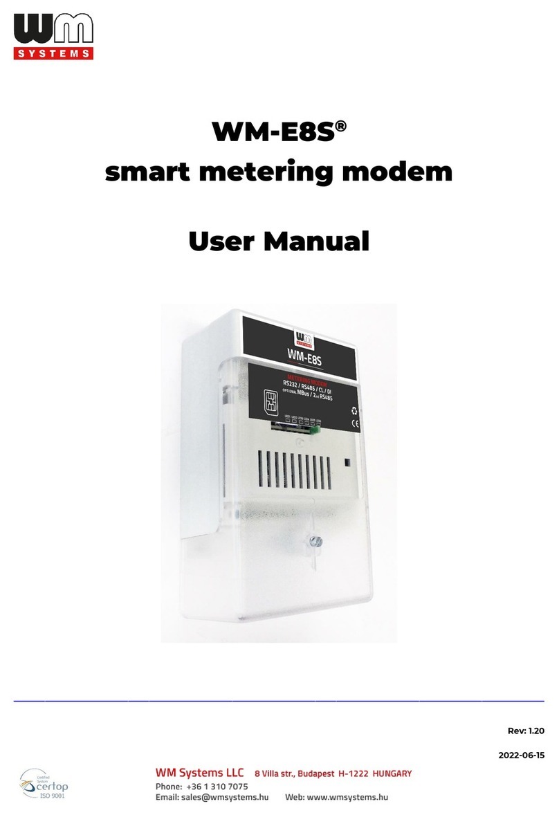
WM Systems WM-E8S User manual

WM Systems
WM Systems WM-E2S User manual