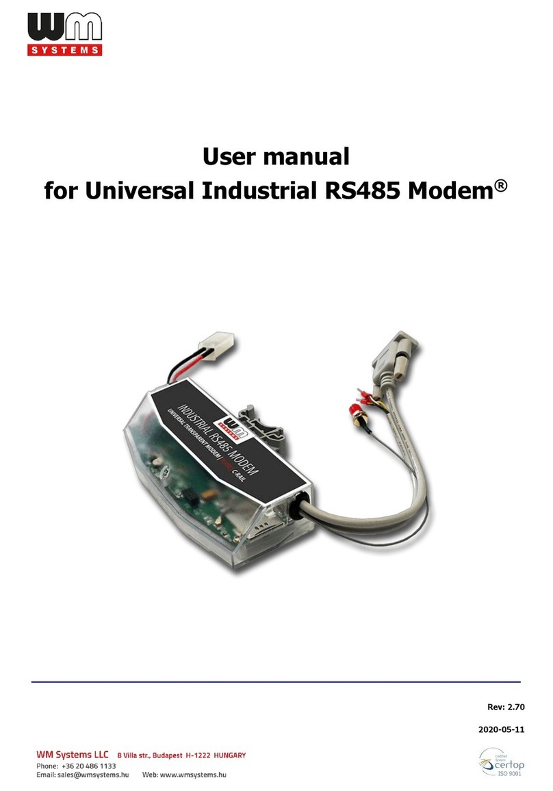
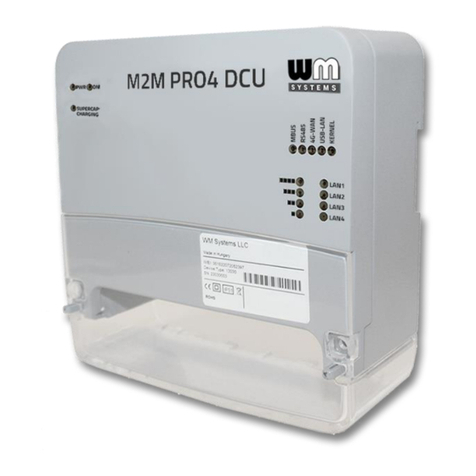
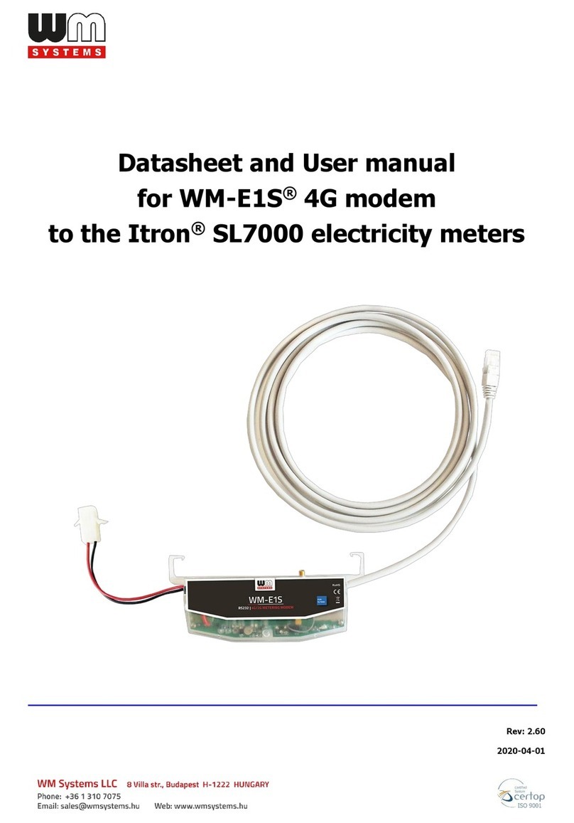
WM Systems WM-E2S User manual

User manual
for WM-E2S ®
electricity metering modems
___________________________________________________
Rev: 2.7.5
2023-11-30

Document specifications
This documentation was made for presenting the installation and configuration
steps of the WM-E2S®(Itron®meter compatible) energy metering modem.
Document Version:
REV 2.75
Hardware Type/Version:
WM-E2S
®
modems
for the ITRON ACE6000, ACE8000, EM600 (E620
),
SL7000 electricity
meters
Hardware Version:
V 2.xx / V 3.xx / V 5.xx
Firmware Version:
for v2 version Telit Modem: V 2.4.43.11 / V 2.5.60 TLS
for v5 version Quectel Modem: V 5.1.58 / V 5.1.58 TLS
WM-E Term®config.
software version:
V 1.3.80
Pages:
36
Status:
Final
Created:
12-09-2019
Last Modified:
30-11-2023

Chapter 1. Introduction
The WM-E2S®modem is suitable for remote reading of electricity meters on LTE-
based cellular networks.
You can save money by using our modem, because there is no further need of manual
readout of the meter systems.
Wireless communication
The 4G LTE version has 2G fallback feature
(or 3G/2G fallback for request). Therefore, in
case of outage or inaccessibility of the 4G
network it is communicating further on the
2G (or 3G) network.
Some LTE Cat.M / Cat.NB versions also
having 2G “fallback” feature.
The modem can be also configured to GSM-CSD connection to initiate the CSData
calls.
The modem includes a removable SIM card and it has independent operation from
mobile service providers.
The modem has been designed to provide transparent data link from the meter to
the HES / central server.
The communication module is a part of the Smart Metering concept. The device
provides a SIM-card independent- and mobile operator independent solution.
Design and installation
This modem was especially developed for 3-phase Itrón®ACE6000, ACE8000, EM600
(E620) and SL7000 energy meters, which can be connected to the meter by its design
and its connection interface and can be installed into the meter enclosure’s terminal
cover. The modem can be snapped into the terminal cover of the meter.
The device can be also installed as an external modem –due an optional 35mm DIN-
rail adapter (order option) - which allows to fix/mount the device.
Operation properties, features
The modem is suitable for reading the meter’s actual and stored consumption values,
access the recorded event log, read the load profile data, and read or modify the
parameter set of the meter - remotely. The date readout from the meter takes place
in "PULL" mode, when the modem provides transparent communication between the
meter and the electricity provider's measurement center (HES).
Data is sent via the mobile network corresponding to the selected module.
The modem can be accessed remotely through the cellular network (by the Telit®
module) and it is able to send data on the Internet by using an APN.
Connection options
The interface connection can be via:
-Serial RS232 port (RJ45)
or
-RS485 port (RJ45)
Power source
The device can be powered from DC power (8-16V DC) of the meter’s RJ45 cable
connection (10V DC).
Supercapacitor
The device can be equipped with internal supercapacitor part (order option), which
prevent the intermittent power cuts also help decrease power peaks. This enables to
keep the module in operation during small power outages.
After a few minutes of charging, the supercapacitor becomes capable of normal
operation and even frequent data transmission of a few minutes.
After the supercapacitor exhausting, it must be charged and the modem can be
automatically started after this and able to send data again.
The modem can also be ordered in a version without supercapacitor.
Configuration
The modem is configurable via TCP/UDP port remotely (or via local serial connection)
and operating on the wireless network by configuring the APN, username and
password (APN information is provided by your local mobile operator).
All settings can be configured with our WM-E Term®administration software. The
configuration is possible by one device or for a group of devices.

The WM-E Term®tool is password protected and user management is also possible.
The configuration tool requires Windows®platform to be executed, and it is available
in English, German, French, Spain, Czech and Hungarian language as well.
Firmware refresh
The WM-E Term®also provides safe firmware change for one or group of devices –by
locally or remotely.
Security
The product’s firmware is encrypted and prevented against to upload firmware or
data from other devices. The modem cannot be upgraded by any other 3rd party
firmware –its safe.
The control port of the modem is encrypted by AES - optional. TLS protocol firmware
is also available (request must be indicated before ordering).
The external flash- and the internal flash content of the device are encrypted.
Status and notification
The modem is continuously monitoring the mobile network and device
communication health, and can send status information (signal strength, QoS).
By the configured features, the device is able to send SMS alarm notification, Last
Gasp notification –depending on the used cellular network and mobile operators (if
the SMS notification is not disallowed on the network, then it can be used).
Certificate
According to the CE certification, the modem complies with the Radio Equipment
Directive - ReD –standard 2014/53/EU. The product is RoHS and CE certified.

Chapter 2. Connections
2.1 External outfit
2.2 Internal connections
2.2.1 Jumperable version
4
1a –Plastic transparent top cover
2 –PCB board
3 –Fixation holes
4 –Cover holders (loosen them to
let it open up the cover)
5 –FME or SMA antenna connector
(50 Ohm) –order option
6 –Status LEDs
7 –Hinge (of top cover)
1a
3
3
5
6
7
1b –Plastic transparent bottom cover part
(white)
8 –SIM card slot (push right & spin up)
9 –Internal antenna wire (with U.LF –FME or
SMA connection)
10 –RJ45 connector (data and DC power)
11 –Jumper board (for RS232 or RS485
mode selection –with jumpers - according
to the meter / cable connection)
12 –Supercapacitors (presence is order option)
13 –External connector (do not use!)
4
8
10
9
11
12
5
13
2
1b

2.2.2 Jumperless version
2.2.3 Modem without supercapacitor
1b –Plastic transparent bottom cover part
(white)
8 –SIM card slot (push left and spin up)
9 –Internal antenna wire (with U.LF –SMA /
FME connection)
10 –RJ45 connector (data and DC power)
11 –Jumper crossboard (for the proper meter
communication / compatible cable pinout)
12 –Supercapacitor parts
13 –External connector (do not use!)
14 –Holder of the top cover
(part of modem enclosure)
8
1
10
9
11
12
5
13
14
8
9
11
5
13
14
10

2.3 Jumper version –port mode choose
The modem can be ordered in a version with or without a jumper. The advantage of
the jumperable version is that the RS232 or RS485 mode can be free to set by the
requirements. While the jumpreless version provides a fixed / non-changeable
connection –which must be selected at ordering - according to the required meter
type - i.e. a fixed RS232 or RS485 connection should be choosen for the exact meter
type. (To choose the right model and pinout, contact our Sales!)
The jumperable version is delivered pre-jumpered, but it may be necessary to use
another method to connect the electric consumption meter. Therefore, the
RS232/RS485 data connection settings of the modem must be checked and, if
necessary, jumpered before use, by short-circuiting the corresponding pins of the
jumper panel (11) next to the RJ45 connector (using the help shown on the jumper
panel) - perform the jumpering.
RS232 mode selection
All the 4 jumpers are located on the inner
two lines of pins and the bottom line pins are
free (as it can be seen in the photo).
The modem is configured to RS232 mode.
Further data connection settings can be
initiated by the WM-E Term®software.
RS485 mode selection
All the 4 jumpers are located on the two
sides, in two lines of pins and the top line
pins are free. The jumpers must be used as it
is shown in the picture.
The modem is configured to RS485 mode.
Further data connection settings can be
initiated by the WM-E Term®software.
11
11

2.4 Jumperless (crossboard) version
The modem can be ordered in jumperless version
(crossboard soldered to the PCB, instead of a jumper
board). It has a pre-defined connection according to the
meter type. Therefore, there is no need for manual
jumpering of the device, all settings can be done by the
WM-E Term®configuration software directly –or even by
remotely.
We can provide crossboard version in the modem for the following meter types:
-ITRON®ACE6000, ACE8000 meters
-ITROL®EM600 (E620) meters
-ITROL®SL7000 meters
-Landis+Gyr®ZMG416 meters
-PME-PMI®meters
or we can make for any other meter (ask our sales)
Jumperless, crossboard version
11
11

Itron®meter - RS232 Connector pinout
Itron®meter –RS485 Connector pinout
RS485 interface description
Symmetric, serial and asynchron 4-wired cable connection. The master in 2-wire cable
mode, which can be configured by configuration software (provided) - Standard ISO-
8482. Maximal 31 meter can be connected.
The maximal data transmitting speed rate is 9 600 bps. Maximal wire length:
<=550 m, max. 9,600 bps, max. 31 meter
<=1000 m, max. 9,600 bps, max. 15 meter
Attention! External power surge protection is needed to apply in case of using
longer cabling. If the RS485 bus is not properly closed, this can disturb the
normal/proper operation.

2.5 Installation steps
Step #1: Remove the top cover or the meter
(18) by loosing its screws.
Step #2: Ensure that the modem is not
powered –remove the RJ45 connection cable
(14) from the meter side.
Step #3: Loose the cover holders (4) of the
plastic enclosure’s white part (1b) at the edges,
while pull the plastic top cover (1a) - from right-down to left-up direction –from the
antenna connector side, and open the cover, until the PCB (2) will be free to touch.

Step #4: Now the PCB (2) will be on
the left side –see the photo.
Step #5: Slide and open up the plastic
SIM card holder (8) - push from left to
right, and spin it up until release.
Step #6: Insert a replaceable and
active SIM card (with APN) into the
SIM-holder (8) - the chip looks down,
the cutted edge of the SIM is oriented to outside –to the antenna connector).
Step #7: Close down the SIM holder (8) and push it from right to left until it is fastened.
Step #8: Ensure that the internal antenna U.FL - black - cable is connected to the U.FL
connector (9)!
Step #9: Close back the PCB-side of the enclosure (transparent plastic) part (1a) to the
white plastic part (1b) from left to right - according and taking patient of the proper
closure at the ears (4) - until the cover will be fastened (you will hear a click sound
when it is closed).
4
1a
8
10
5
7
1b
9
4

Step #10: The data connection between the modem and Itrón®meter is assured by
the RS232/RS485 interface (RJ45, signed with nr. 10 on the figure), then it can be used
with the grey RJ45 cable - provided.
Step #11: Place and insert the modem into the meter (under the meter’s terminal
cover) and fix the device to the meter –according to the meter’s installation manual.
(By optionally the modem can be ordered with DIN-rail adapter (which is fixed to the
bottom side of the modem enclosure), therefore you can also use the modem as an
external device).
Step #12: Mount the FME (or SMA) antenna (15) to the antenna connector (5) and the
communication antenna (15). (If you are using an SMA antenna, then you can use a
SMA-FME converter adapter (17) to mount the SMA antenna to the FME connector).
Step #13: For configuring the modem, connect the device to the computer by an RJ45
cable and the USB/RS232 DONGLE adapter, and configure the jumper positions to
RS232 modem.
Important! Note, that the modem directly can be configured only in RS232 mode. For
RS485 mode configuration you should use an RS485 USB-Dongle (order option).
Step #14: Configure the modem with the WM-E Term®software.
Step #15: After the configuration, do the jumpering (11) according to the meter
requirements. (Close the jumper pairs according the hints of the PCB):
•RS232 mode: the jumpers are closed on the internal pin pairs, the edge pins are
free
•RS485 mode: the edge pin pairs are closed by jumpers, the internal pins are free
(If you are using a crossboard version instead of a jumper board, then the jumpering
is not necessary to make.)

Step #16: Reconnect the RJ45 cable to the meter. (If the modem will be connected on
RS485 port with the meter, then the jumper settings must be modified to RS485
mode!)
ITRON ACE6000
→
WM-E2S modem connection
16
10
14
15
17
18
5

ITRON SL7000
→
WM-E2S modem connection
16
10
14
15
5

ITRON EM600 (E620) meter
→
WM-E2S modem connection
16
10
14
5
15
17

Step #17: The data connection between the modem and the Itron®meter can be
initiated on the RS232 or RS485 interface by using 1:1 cable connection, which can be
made by using grey RJ45 cable (14) of the modem –connect it to the RJ45 port (10).
Step #18: Connect the other side of the RJ45 cable to the meter’s RJ45 connector (16)
according to the meter type, and readout port of the meter (RS232 or RS485). Then
the modem will be powered by the meter. It begins its operation, check LED signals.
Step #19: Place back the meter’s terminal cover (18).
2.5 Status LED signals
If the WM-E2S®modem was not supplied by power source since a long time, it needs
to be charged before the usage/installation. The charge takes about ~2-5 minutes if
the supercapacitor was exhausted / discharged.
OPERATION LED SIGNALS - IN CASE OF CHARGING
Important! The LED number we’ve listed here are the same as can be found on the
PCB LED title (as LED3 (green, top), LED1 (blue, middle), LED2 (red, bottom).
At the first power on - during the
charge –the green LED is
flashing quickly. After a few
minutes the LED will be blank,
then qill be flashing quickly
again. When the green LED will
be flashing slowly and the other
LEDs will be lighting according
the NORMAL operation, then the
modem will be charged
completely and it will be ready
for congfiuring and to operate.
LED
Color
Signal
Description
Green
●
During the charging of the exhausted supercapacitors, only green upper LED
will flashing quickly. Only this LED is active during the charge. Wait until the
device will be fully charged.
LED 3
LED 1
LED 2

OPERATION LED SIGNALS –IN CASE OF NORMAL OPERATION
Factory default LED signals:
LED identifier
Events
LED 3
E-METER status
•By general: the led is inactive
•During communication: the led is active (flashing)
LED 1
GSM / GPRS status
•During network registration: led is active
•During network searching: blinking once per second
•When connected to the network and the IP connection is
okay: blinking twice per second
•When the mobile network access technology was changed:
quick flashing will be relied:
o2G →2 flashing per second
o3G →3 flashing per second
o4G LTE →4 flashing per second
•If there is no available cellular network detected: the led will
be blank
•During the CSD call and IP data forwarding, the LED is
ligthing continuously
LED 2
SIM status / SIM or PIN
failure)
•Continuously lighting, until the device is not on the cellular
network and RSSI cannot be detected (SIM okay)
•When the SIM PIN is okay: led is active
•If there is no SIM detected or SIM PIN is wrong: blinking once
per second (slow flashing)
•The RSSI (signal strength) value is signed also by this led.
Flashing by “N” times in every 10-15 seconds, depending on
the RSSI refresh period. The RSSI value can be 1,2,3 or 4 on
the current cellular network.
The numbers of RSSI flashing is different on every available
network technology, by the following:
oon 2G network:
o1 flashing: RSSI >= -98
o2 flashings: RSSI between -97 and -91
o3 flashings: RSSI - between 90 and -65
o4 flashings: RSSI > -64
oon 3G network:
o1 flashing: RSSI >= -103
o2 flashings: RSSI between -102 and -92
o3 flashings: RSSI - between 91 and -65
o4 flashings: RSSI > -64
oon 4G LTE network:
o1 flashing: RSSI >= -122
o2 flashings: RSSI between -121 and -107
o3 flashings: RSSI between -106 and -85
o4 flashings: RSSI > -84
oon LTE Cat.M1 network:
o1 flashing: RSSI >= -126
o2 flashings: RSSI between -125 and -116
o3 flashings: RSSI between -115 and -85
o4 flashings: RSSI > -84
oon LTE Cat. NB-IoT (Narrow Band) network:
o1 flashing: RSSI >= -122
o2 flashings: RSSI between -121 and -107
o3 flashings: RSSI between -106 and -85
o4 flashings: RSSI > -84

Over the factory defaults, the operation and the sequence of the LED signals can be
changed by the WM-E Term®configuration tool, in Standard Meter Interface
parameter group.
There you can define one of the following functions of the leds (LED1..LED3) according
the next list:
Selectable LED status (in the WM-E Term program)
Not used
GSM / GPRS status
SIM status (wrong PIN flashing slow or without SIM )
E-meter status
E-meter relay status (not usable here)
M-Bus status (not usable here)
Firmware status
Network status and access technology
Meter status with IEC polling
AMM (IEC) client state (not usable here)
LED status
Events
E-meter relay status –
Status of the E-meter relay
output (available only in
case of WM-E3S CIR
modem type)
•General: “Ready” / stand-by –the led is flashing 1x per seconds.
•In “Active” mode – at *relay switching it turns on the led
(ligthing).
In “Normal” mode – by releasing the *relay it turns off the led
(blank).
Firmware status
•When the modem firmware was started, the led will be turned
on (ligthing).
•When the meter →modem connection was built up then the
led will be flashing 2x per seconds.
Network status and
access technology
•Network registration: the led is active (lighting).
•During network searching: the led is flashing 1x per seconds.
•When it was connected to the network and the IP connection
is okay: the led is flashing 2x per seconds.
•If the mobile access technology was changed –it will be signed
by quick flashing:
o2G →2 flashing / seconds
o3G →3 flashing / seconds
o4G →4 flashing / seconds
•If there is no available network: the led is inactive (blank)
Meter status with IEC
polling –Meter status
during the IEC
communication
•When the modem→meter starting the communication, the
led will be flashing 1x per seconds.
•When the meter is answering to the modem during the
communication, it will turns on the led.
•When the modem→ meter cannot communicate with each
other, the led will be turned off.
AMM (IEC) client state
•By general or in case of closing the modem→EI client
communication the LED is turned off.
•In case of building up the modem→ EI client** connection
the led is flashing shorty 1x per seconds (then 1 second of
pause will be progressed between the flashings)
•In case of EI client** login request attempt–the led is flashung
1x per seconds.
•When the connection was built up successfully between the EI
client**→modem–the led is active (ligthing).

*The listed relay can switch the power source of the e-meter. it cannot be used for tarrif switch!
**The EI client is the transparent output TCP channel from the modem to the EI server
In Connected “normal” mode (when the relay is released), the LED is turned off.
In Ready for Connection “ready” (stand-by) mode,
During the firmware uploading the LEDs are operating as it is normal –there is no
significal LED signal for the FW refresh progress.
After the FW installation all LEDs will be blank. Then the modem will be restarted
automatically, and will be operating by the new firmware.
At starting the LED3 will be flashing quickly by green for 15 seconds. The starting
requires 2-3 minutes while the modem will be available on its interfaces.
Afterall, the LED will be operating ordinary as it is listed in the LED operation
behaviour description.
2.6 LED operation during CSD call
During the CSD call two operation option types can be used:
a.) When the meter would be read out / configured in transparent mode
b.) When modem configuration / firmware refresh is attempted to make
When the meter would be read out / configured in transparent mode:
- The GSM / GPRS status configured LED will be continously lighting during the CSD
call.
- The e-Meter status configured LED will be operating according the CSD call status by
the following:
•Will be flashing twice per seconds from the connection attempt until closing the
connection
•If the meter interface is not configured to 9600 baudrate, then it will be ligthing
continuously from the connection attempt until closing the connection
•After the connection close the LED will be switched off
Other manuals for WM-E2S
1
Table of contents
Other WM Systems Modem manuals

WM Systems
WM Systems WM-E3S User manual

WM Systems
WM Systems Universal Industrial RS485 Modem User manual

WM Systems
WM Systems M2M PRO4 DCU User manual

WM Systems
WM Systems WM-E8S User manual

WM Systems
WM Systems M2M PRO4 MODEM User manual

WM Systems
WM Systems WM-E1S User manual

WM Systems
WM Systems WM-I2 User manual

WM Systems
WM Systems WM-E1S User manual

WM Systems
WM Systems M2M PRO4 MODEM User manual

WM Systems
WM Systems WM-E3S 4G CI User manual