Wolf 15" User manual

INSTALLATI N GUIDE
Induction and Electric Cooktops

Important Note
To ensure the safe and efficient use of Wolf equipment,
please take note of the following types of highlighted
information throughout this guide:
IMP RTANT N TE highlights information that is especially
important.
CAUTI N signals a situation where minor injury or product
damage may occur if instructions are not followed.
WARNING states a hazard that may cause serious injury or
death if precautions are not followed.
Contents
Wolf Induction and Electric Cooktops . . . . . . . . . . . . . 3
Cooktop Specifications . . . . . . . . . . . . . . . . . . . . . . . . 4
CooktopInstallation ..........................14
ServiceInformation...........................18
Features and specifications are subject to change at any time
without notice. Visit wolfappliance.com/specs for the most
up-to-date information.
IMP RTANT N TE: Throughout this guide, dimensions in
parentheses are millimeters unless otherwise specified.

Wolf Induction and Electric Cooktops 3
wolfappliance.com/specs
Induction and Electric Cooktops
IMP RTANT N TE: This installation must be completed
by a qualified installer or Wolf factory certified service.
Read this entire installation guide prior to installation and
save for the local inspector’s reference. The homeowner
should keep this installation guide for future reference.
This appliance must be installed in accordance with
National Electrical Codes, as well as all state, municipal
and local codes. The correct voltage, frequency and
amperage must be supplied to the appliance from a dedi-
cated, grounded circuit which is protected by a properly
sized circuit breaker or time delay fuse. The proper
voltage, frequency and amperage ratings are listed on the
product rating plate.
Record the model and serial numbers before installing the
cooktop. Both numbers are listed on the product rating
plate, located on the underside of the cooktop. Refer to
the illustrations below for location of the rating plate.
Wolf Induction or Electric Cooktop
Model Number
Serial Number
MEL
TOFF
HI-POWER
HIGH
SIMOFFON
HI-POWER
HIGH
SIMOFFON
MEL
THIGH
OFFON
Induction cooktop. Electric cooktop.
SIMHIGH
OFFON
OFFON
SIMHIGH
OFFON
SIMHIGH
BRIDGE
ZONE2
ZONE3
HIGH
MEL
TOFFON
RATING P ATE RATING P ATE

Cooktop Specifications 4
21/2"(64)
11/4"(32) 7/8"(22)
ALL SIDES
21" (533)
15"
(381)
CONDUIT
15" (381) FRAMED
21/2"(64)
30" (762)
11/4"(32) 7/8"(22)
ALL SIDES
21" (533)
CONDUIT
30" (762) FRAMED
36" (914)
21/2"(64)
11/4"(32) 7/8"(22)
ALL SIDES
21" (533)
CONDUIT
36" (914) FRAMED
30" (762)
11/4"(32) 7/8"(22)
ALL SIDES
21" (533)
3" (76)
CONDUIT
30" (762) UNFRAMED
36" (914)
3" (76)
11/4"(32) 7/8"(22)
ALL SIDES
CONDUIT
21" (533)
36" (914) UNFRAMED
Induction Cooktops
VERALL DIMENSI NS

Cooktop Specifications 5
wolfappliance.com/specs
Electric Cooktops
VERALL DIMENSI NS
11/4"(32) 7/8"(22)
ALL SIDES
33/4"(96)
CONDUIT
21" (533)
15"
(381)
15" (381) FRAMED
30" (762)
21" (533)
11/4"(32) 7/8"(22)
ALL SIDES
33/4"(96)
CONDUIT
30" (762) FRAMED
36" (914)
11/4"(32) 7/8"(22)
ALL SIDES
33/4"(96)
CONDUIT
21" (533)
36" (914) FRAMED
30" (762)
41/4"(108)
11/4"(32) 7/8"(22)
ALL SIDES
CONDUIT
21" (533)
30" (762) UNFRAMED
36" (914)
41/4"(108)
11/4"(32) 7/8"(22)
ALL SIDES
CONDUIT
21" (533)
36" (914) UNFRAMED

Cooktop Specifications 6
Electrical Requirements
Wolf induction and electric cooktops have a 4' (1.2 m)
flexible conduit and require a separate, grounded 3-wire
electrical supply with its own circuit breaker. ocate the
electrical supply within the shaded area shown in the
installation illustration for your specific model on the
following pages.
IMP RTANT N TE: You must follow all National Electrical
Code regulations. In addition, be aware of local codes and
ordinances when installing your service.
IMP RTANT N TE: Except for model CT30E-208/S,
performance may be compromised if the electrical supply
is less than 240 volts.
Induction Cooktops
CT15I/S
Power Supply 240/208 V AC, 60 Hz
Service 20 amp
Max Connected oad 3.6 kW at 240 / 3.1 kW at 208
CT30I/S AND CT30IU
Power Supply 240/208 V AC, 60 Hz
Service 40 amp
Max Connected oad 7.2 kW at 240 / 6.3 kW at 208
CT36I/S AND CT36IU
Power Supply 240/208 V AC, 60 Hz
Service 50 amp
Max Connected oad 11.2 kW at 240 / 9.7 kW at 208
Electric Cooktops
CT15E/S
Power Supply 240/208 V AC, 60 Hz
Service 20 amp
Max Connected oad 3.7 kW at 240 / 2.8 kW at 208
CT30E-208/S
Power Supply 208 V AC, 60 Hz
Service 40 amp
Max Connected oad 7.9 kW
CT30E/S AND CT30EU
Power Supply 240/208 V AC, 60 Hz
Service 40 amp
Max Connected oad 8.1 kW at 240 / 6.1 kW at 208
CT36E/S AND CT36EU
Power Supply 240/208 V AC, 60 Hz
Service 50 amp
Max Connected oad 10.5 kW at 240 / 7.9 kW at 208

Cooktop Specifications 7
wolfappliance.com/specs
Electrical Requirements
IMP RTANT N TE: For electrical installation, attach the
conductors to the residence wiring in accordance with
National Electrical Codes and all state, provincial, munici-
pal and local codes.
This appliance must be installed in accordance with
National Electrical Codes, as well as all state, municipal
and local codes. The correct voltage, frequency and
amperage must be supplied to the appliance from a dedi-
cated, grounded circuit which is protected by a properly
sized circuit breaker or time delay fuse. The proper
voltage, frequency and power ratings are listed on the
product rating plate, located on the underside of the
cooktop. Refer to the illustrations on page 3 for location
of the rating plate.
The complete appliance must be properly grounded at
all times when electrical power is applied.
Do not ground appliance with the neutral (white) house
supply wire. A separate ground wire must be utilized.
If aluminum house supply wiring is utilized, splice the
appliance copper wire to the aluminum house wiring
using special connectors design and agency certified
for joining copper and aluminum. Follow the connector
manufacturer's recommended procedure carefully.
Improper connection can result in a fire hazard.

Cooktop Specifications 8
Installation Requirements
IMP RTANT N TE: Installation of the induction or electric
cooktop must meet location requirements shown in the
installation illustration for your specific model on the
following pages. All dimensions listed are minimum
requirements for safe operation.
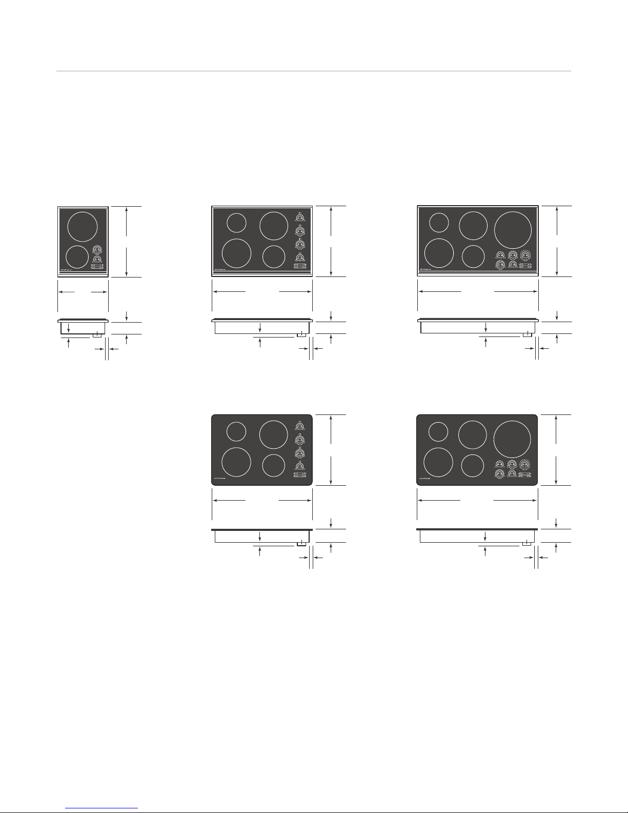
Wolf induction and electric cooktops are intended for
indoor use. For ease of installation, Wolf recommends
using 33" (838) wide cabinets with 30" (762) cooktops and
39" (991) cabinets with 36" (914) cooktops. They are
designed to fit a standard 24" (610) deep base cabinet with
a 25" (635) deep countertop. Before making the countertop
cut-out, verify that the cooktop will clear the side walls of
the base cabinet.
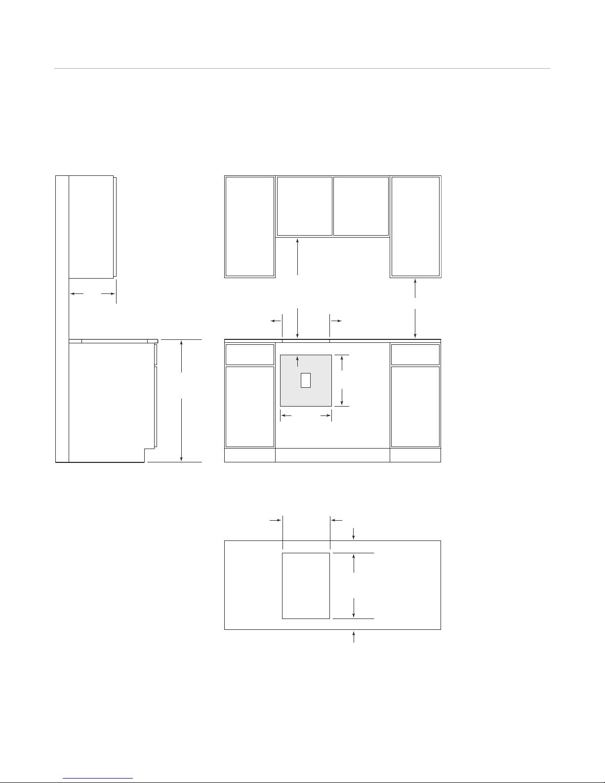
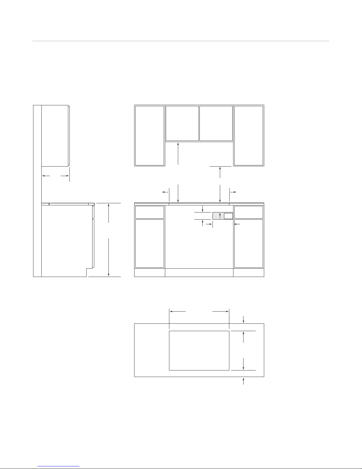
A minimum height clearance of 61/4"(159) is required from
the top of the countertop to any combustible surface
directly below the cooktop. For induction cooktops, if a
shelf is installed below the unit, a 1" (25) gap at the rear of
the shelf is necessary to allow for proper ventilation.
Clearance is required for the conduit located at the right
rear of induction and electric cooktops. Refer to the illus-
tration below for dimensions.
Failure to locate the cooktop without proper clearances
will result in a fire hazard.
It is recommended that you use a Wolf cooktop ventilation
hood, pro hood or hood liner with induction and electric
cooktops. Framed cooktops can accommodate a Wolf
downdraft ventilation system. Refer to the Wolf design
guide.
11/4"(32)
2"
(51)
2"
(51)
Conduit dimensions.

Cooktop Specifications 9
wolfappliance.com/specs
36" (914)
FLOOR TO
COUNTERTOP
30" (762) min
COUNTERTOP
TO COMBUSTIBLE
MATERIALS
SEE COUNTERTOP
CUT-OUT BELOW
133/8"(340)
CUT-OUT
WIDTH
COUNTERTOP CUT-OUT
FRONT
191/4"(489)
CUT-OUT
DEPTH
21/2"(64) min
2" (51) TO
COMBUSTIBLE*
2" (51) TO
COMBUSTIBLE*
SIDE
CABINET
13" (330)
max
E
15" (381)
15"
(381)
41/2"(114)
18" (457) min
2" (51) min*
FRONT VIEWSIDE VIEW
*Minimum clearance from cooktop cut-out to combustible materials up to 18" (457) above countertop.
NOTE: Application shown allows for installation of two 15" (381) modules side by side.
15" (381) Framed Induction and Electric Cooktops
STANDARD INSTALLATI N

Cooktop Specifications 10
18" (457) min
36" (914)
FLOOR TO
COUNTERTOP
30" (762) min
COUNTERTOP
TO COMBUSTIBLE
MATERIALS
41/2"(114)
10" (254)
31/2"(89) E
SEE COUNTERTOP
CUT-OUT BELOW
2" (51) TO
COMBUSTIBLE*
2" (51) TO
COMBUSTIBLE*
SIDE
CABINET
13" (330)
max
283/8"(721)
CUT-OUT WIDTH
COUNTERTOP CUT-OUT
FRONT
191/4"(489)
CUT-OUT
DEPTH
21/2"(64) min
2" (51) min*
FRONT VIEWSIDE VIEW
*Minimum clearance from cooktop cut-out to combustible materials up to 18" (457) above countertop.
NOTE: Electrical location applies only to installation with built-in oven.
30" (762) Framed Induction and Electric Cooktops
STANDARD INSTALLATI N

Cooktop Specifications 11
wolfappliance.com/specs
18" (457) min
36" (914)
FLOOR TO
COUNTERTOP
30" (762) min
COUNTERTOP
TO COMBUSTIBLE
MATERIALS
41/2"(114)
10" (254)
31/2"(89) E
SEE COUNTERTOP
CUT-OUT BELOW
343/8"(873)
CUT-OUT WIDTH
COUNTERTOP CUT-OUT
FRONT
191/4"(489)
CUT-OUT
DEPTH
21/2"(64) min
2" (51) TO
COMBUSTIBLE*
2" (51) TO
COMBUSTIBLE*
SIDE
CABINET
13" (330)
max
2" (51) min*
FRONT VIEWSIDE VIEW
*Minimum clearance from cooktop cut-out to combustible materials up to 18" (457) above countertop.
NOTE: Electrical location applies only to installation with built-in oven.
36" (914) Framed Induction and Electric Cooktops
STANDARD INSTALLATI N

Cooktop Specifications 12
18" (457) min
36" (914)
FLOOR TO
COUNTERTOP
30" (762) min
COUNTERTOP
TO COMBUSTIBLE
MATERIALS
41/2"(114)
10" (254)
31/2"(89) E
SEE COUNTERTOP
CUT-OUT BELOW
283/8"(721)
CUT-OUT WIDTH
COUNTERTOP CUT-OUTRECESS FOR FLUSH INSTALLATION
FRONT
193/8"(492)
CUT-OUT
DEPTH
27/16"(62) min
211/8"(537)
RECESS
FOR FLUSH
INSTALLATION
19/16"(40)
2" (51) TO
COMBUSTIBLE*
2" (51) TO
COMBUSTIBLE*
SIDE
CABINET
13" (330)
max
5/16"(8)
7/8"
(22) max
COUNTERTOP
PROFILE
15/16"(33)
RADIUS
7/16"(11) RADIUS
301/8"(765)
RECESS FOR FLUSH INSTALLATION
2" (51) min*
FRONT VIEWSIDE VIEW
*Minimum clearance from cooktop cut-out to combustible materials up to 18" (457) above countertop.
NOTE: Electrical location applies only to installation with built-in oven.
30" (762) Unframed Induction and Electric Cooktops
FLUSH M UNT INSTALLATI N

Cooktop Specifications 13
wolfappliance.com/specs
18" (457) min
36" (914)
FLOOR TO
COUNTERTOP
30" (762) min
COUNTERTOP
TO COMBUSTIBLE
MATERIALS
41/2"(114)
10" (254)
31/2"(89) E
SEE COUNTERTOP
CUT-OUT BELOW
343/8"(873)
CUT-OUT WIDTH
COUNTERTOP CUT-OUTRECESS FOR FLUSH INSTALLATION
FRONT
193/8"(492)
CUT-OUT
DEPTH
27/16"(62) min
211/8"(537)
RECESS
FOR FLUSH
INSTALLATION
19/16"(40)
2" (51) TO
COMBUSTIBLE*
2" (51) TO
COMBUSTIBLE*
SIDE
CABINET
13" (330)
max
5/16"(8)
7/8"
(22) max
COUNTERTOP
PROFILE
15/16"(33)
RADIUS
7/16"(11) RADIUS
361/8"(918)
RECESS FOR FLUSH INSTALLATION
2" (51) min*
FRONT VIEWSIDE VIEW
*Minimum clearance from cooktop cut-out to combustible materials up to 18" (457) above countertop.
NOTE: Electrical location applies only to installation with built-in oven.
36" (914) Unframed Induction and Electric Cooktops
FLUSH M UNT INSTALLATI N

Cooktop Installation 14
Multiple Cooktop Installation
IMP RTANT N TE: Unframed induction and electric
cooktops are not designed to be installed in combination
with other cooktops.
If the framed induction or electric cooktop is to be used
with any combination of additional cooktops or modules
with a filler strip, the dimensions provided in the chart
below are derived by adding 11/4"(32) additional space for
each additional unit, to give you the total countertop cut-
out width. Dimensions include the filler strip.
IMP RTANT N TE: For models CT15I/S and CT15E/S, the
cut-out width should be increased from 133/8"(340) to 14"
(356) when installed with multiple cooktops.
When multiple cooktops are installed side by side, each
unit must have its own separate recommended electrical
circuit.
When two or more modules are installed together, an
integrated module filler strip is recommended. If a 30" (762)
downdraft ventilation system is also installed, an inte-
grated module support for downdraft ventilation is also
required.
The filler strip and other accessories are available through
your authorized Wolf dealer. For local dealer information,
visit the find a showroom section of our website,
wolfappliance.com.
Multiple Cooktops
C UNTERT P CUT- UT WIDTH
2 Modules 291/4"(743)
3 Modules 441/2"(1130)
4 Modules 593/4"(1518)
30" (762) Cooktop / Module 441/4"(1124)
30" (762) Cooktop / 2 Modules 591/2"(1511)
36" (914) Cooktop / Module 501/4"(1276)
Unframed Installations
Unframed induction and electric cooktops can be
mounted flush with the top of the countertop or as a
frameless installation with the glass-ceramic top mounted
on top of the countertop surface. In either installation the
countertop cut-out dimensions are the same. If the
cooktop is to be mounted flush with the countertop, a
recessed area surrounding the countertop cut-out must
be provided. Refer to the installation illustrations on
pages 12–13.
IMP RTANT N TE: An installation kit and additional
instructions required for a flush mount installation
are provided with the unframed cooktop. The template
provided with the unframed cooktop is for reference only.
Use the actual cooktop for marking the cut-out.
Flush mount installations are intended for granite, solid
surface or stone countertop surfaces only. Contact
with hot cookware may cause damage to countertop
surfaces that are not resistant to high heat.

FLUSH M UNT INSTALLATI N— PTI N 2
For this flush mount installation, the countertop cut-out
will be the same size as the outer edge of the glass-
ceramic top. It is recommended that unframed cooktop
itself be used as the template for the cut-out. Turn the
cooktop over and mark the opening using the glass-
ceramic top as a template.
It will be necessary to attach -shaped cleats to the inner
perimeter of the countertop cut-out to support the
unframed cooktop. The top edge of the cleat can be no
wider than 7/8"(22) and will be attached 5/16" (8) below the
surface of the countertop. Refer to the illustration below.
Attach the cleats wherever enough countertop material is
present.
For additional support in the cut-out area, adhere scrap
countertop material to the bottom side of the countertop.
Consult your countertop supplier for the proper methods
of attachment.
Cooktop Installation 15
wolfappliance.com/specs
Unframed Installations
FLUSH M UNT INSTALLATI N— PTI N 1
For this flush mount installation, a recessed area
surrounding the standard countertop cut-out is required.
Fabrication of the recessed area must take place before
the final countertop installation. A template of the counter-
top cut-out is provided with the unframed cooktop for
fabrication purposes.
IMP RTANT N TE: This option is not recommended for
molded backsplash style countertops.
In order to rout the required recessed area for this flush
mount installation, a second template must be made from
1/2"(13) plywood. The template will be used as a guide for
a top-bearing router bit.
Make the wood template wide enough so that clamps
used to hold the template to the countertop do not inter-
fere with the router base. The cut-out dimension of the
wood template should match the outer perimeter of the
template supplied with the cooktop.
Center the wood template over the existing cut-out in the
countertop and clamp. Use double-sided tape to adhere
the template to the countertop to keep the template from
shifting during routing. Make sure that the adhesive can
be easily removed by testing it on a scrap piece of the
countertop. Using a top-bearing router bit with the wood
template as a guide, rout out a 5/16"(8) deep recessed area
in the countertop cut-out.
7/8"(22)
5/16"(8)
L-SHAPED
CLEATS
Support cleats.

Cooktop Installation 16
Install the Cooktop
Attach the foam strip to the underside of the cooktop
frame. Refer to the illustration. For unframed cooktops, be
sure to adhere the foam strip to the outer edge of the
glass-ceramic top, not the support frame.
Gently lower the cooktop into the cut-out area in the
countertop and center. Check that the front edge of the
cooktop is parallel to the front edge of the countertop.
Check that all required clearances are met.
Attach the brackets to the bottom of the cooktop, as
shown in the illustration. Install clamping screws into the
brackets and tighten until the screws contact the under-
side of the countertop. Do not overtighten screws.
IMP RTANT N TE: Do not seal the cooktop to the coun-
tertop. It must be removed if service is necessary.
FOAM
STRIP
COOKTOP FRAME
Foam strip. Installation brackets.
COUNTERTOP
BRACKET
SCREWS
BRACKET
4" (102)
CLAMPING
SCREW

Cooktop Installation 17
wolfappliance.com/specs
Verify Cooktop Operation
Before operating the induction or electric cooktop, be
sure to read the entire use & care guide included with the
cooktop for important safety, operating and warranty
information.
Clean the glass-ceramic surface as recommended in the
induction or electric cooktops use & care guide. The
cooktop surface must be free of any foreign substances,
especially those that could melt and permanently adhere
to the glass-ceramic.
Turn on the electrical supply to the cooktop. Check opera-
tion of the controls and verify that each of the elements is
coming up to temperature.
IMP RTANT N TE: A small amount of smoke and odor
may be noticed during the initial break-in period.
Do not operate the cooktop if the glass-ceramic surface
is broken. Contact Wolf factory certified service.
Cooktop Removal
IMP RTANT N TE: Cooktop removal should only be done
by Wolf factory certified service.
If it is necessary to remove the cooktop for cleaning or
service, disconnect the electrical supply. Remove the
mounting brackets and remove the cooktop. Reinstall in
the reverse order.
For flush mount installations, use a razor blade to carefully
cut around the perimeter seal. A new RTV installation kit
will be required to reinstall the cooktop. This kit and other
accessories are available through your authorized Wolf
dealer. For local dealer information, visit the find a
showroom section of our website, wolfappliance.com.

Troubleshooting
IMP RTANT N TE: If the induction or electric cooktop
does not operate properly, follow these troubleshooting
steps:
•Verify that electrical power is being supplied to the
cooktop.
•Check the electrical connections to ensure that the
installation has been completed correctly.
•Refer to the troubleshooting guide in the induction or
electric cooktops use & care guide.
•If the cooktop still does not operate properly, contact
Wolf factory certified service. Do not attempt to repair
the cooktop yourself. Wolf is not responsible for
service required to correct a faulty installation.
Service Information
If service is necessary, maintain the quality built into your
cooktop by contacting Wolf factory certified service.
For the name and number of Wolf factory certified service
nearest you, check the contact & support section of our
website, wolfappliance.com or call Wolf customer care at
800-222-7820.
When calling for service, you will need the model and
serial numbers of the induction or electric cooktop. Both
numbers are listed on the product rating plate, located on
the underside of the cooktop. Refer to the illustrations
below for location of the rating plate.
Service Information 18
MEL
TOFF
HI-POWER
HIGH
SIMOFFON
HI-POWER
HIGH
SIMOFFON
MEL
THIGH
OFFON
Induction cooktop. Electric cooktop.
SIMHIGH
OFFON
OFFON
SIMHIGH
OFFON
SIMHIGH
BRIDGE
ZONE2
ZONE3
HIGH
MEL
TOFFON
RATING P ATE RATING P ATE

The information and images in this guide are the copyright property of Wolf Appliance, Inc. Neither this guide nor any information or images contained herein
may be copied or used in whole or in part without the express written permission of Wolf Appliance, Inc. ©Wolf Appliance, Inc. all rights reserved.
Wolf, Wolf & Design, Wolf Gourmet, W & Design and the color red as applied to knobs are registered trademarks and service marks of Wolf Appliance, Inc.
Sub-Zero, Sub-Zero & Design, Dual Refrigeration, Constant Care and The iving Kitchen are registered trademarks and service marks of Sub-Zero, Inc.
(collectively, the “Company Marks.”) All other trademarks or registered trademarks are property of their respective owners in the United States and other countries.

W LF APPLIANCE, INC. P. . B X 44848 MADIS N, WI 53744 W LFAPPLIANCE.C M 800.222.7820
819062 REV-A 10/2011
This manual suits for next models
2
Table of contents
Other Wolf Cooktop manuals

Wolf
Wolf CT30G Instructions for use

Wolf
Wolf CT15E/S Owner's manual

Wolf
Wolf CT36E/B User manual

Wolf
Wolf SRT304 Instructions for use

Wolf
Wolf ICBGC152T/S User manual

Wolf
Wolf CTI Series User manual

Wolf
Wolf 381 User manual

Wolf
Wolf ICBCT15E Owner's manual

Wolf
Wolf ICBCT15E User manual

Wolf
Wolf CT30IU User manual

Wolf
Wolf CT30EU Instructions for use

Wolf
Wolf CT36G Instructions for use

Wolf
Wolf CI36560T/S User manual

Wolf
Wolf CT36EU User manual

Wolf
Wolf Gas cooktop User manual

Wolf
Wolf CT15E User manual

Wolf
Wolf IR304PE/S/PH User manual

Wolf
Wolf RT484CG Instructions for use

Wolf
Wolf CT30E Instructions for use

Wolf
Wolf CT15I/S Instructions for use