Wolf 2 Series Operating manual

Technical Service Manual
Gas Cooktop-
Gas Cooktop-2
2Series
Series
CT15G-2, CT30G-2, CT36G-2
© WOLF APPLIANCE COMPANY, L.L.C. • 2006 ALL RIGHTS RESERVED • 806334 • Revision B


General Information
1-1
GGAASSCCOOOOKKTTOOPP--
GGAASSCCOOOOKKTTOOPP--22
22SSEERRIIEESS
SSEERRIIEESS
SECTION 1
GENERAL INFORMATION

General Information
1-2
GGAASSCCOOOOKKTTOOPP--
GGAASSCCOOOOKKTTOOPP--22
22SSEERRIIEESS
SSEERRIIEESS
INTRODUCTION
This Wolf Gas Cooktop-2 Series Technical Service Manual, Part #806334, has been compiled to provide the most
recent technical service information about the Wolf Gas Cooktops. This information will enable the service techni-
cian to troubleshoot and diagnose malfunctions, perform necessary repairs and return a Wolf Gas Cooktop-2Series
to proper operational condition.
The service technician should read the complete instructions contained in this Service Manual before initiating any
repairs on a Wolf Appliance.
* Some information in Section 2, Theory of Operation, has been provided by the American Gas Association
and reprinted with their approval.
IMPORTANT SAFETY INFORMATION
Below are the Product Safety Labels used in this manu-
al. The "Signal Words" used are WARNING and
CAUTION.
Please note that these safety labels are placed in areas
where awareness of personal safety and product safety
should be taken and lists the precautions to be taken
when the signal word is observed.
TECHNICAL ASSISTANCE
If you should have any questions regarding a Wolf
appliance and/or this manual, please contact:
Wolf Appliance Company, LLC
ATTN: Service Department
P.O. Box 44988
Madison, WI 53744-4988
Customer Service
Phone #: (800) 332 - 9513
Technical Assistance
Phone #: (800) 919 - 8324
Parts / Warranty Claims
Phone #: (800) 332 - 9513
Customer Service E-Mail Address
Customer Service & Technical Assistance
Facsimile #: (608) 441 - 5887
Parts / Warranty Claims
Facsimile #: (608) 441 - 5886
Office Hours:
7:00 AM to 7:00 PM Central Standard Time
Monday through Friday
This manual is designed to be used by Authorized Service Personnel only. Wolf Appliance Company, LLC.
assumes no responsibility for any repairs made to Wolf appliances by anyone other than Authorized
Service Technicians.
INDICATES THAT HAZARDOUS OR UNSAFE PRAC-
TICES COULD RESULT IN SEVERE PERSONAL
INJURY OR DEATH.
Indicates that hazardous or unsafe practices could
result in minor personal injury or product and/or
property damage.
In addition, please pay attention to the signal word
“NOTE”, which highlights especially important informa-
tion within each section.
The information and images are the copyright property of Wolf Appliance Company, LLC, an affiliate of Sub-Zero
Freezer Company, Inc. Neither this manual nor any information or images contained herein may be copied or used
in whole or in part without the express written permission of Wolf Appliance Company, LLC, an affiliate of Sub-Zero
Freezer Company, Inc. © Wolf Appliance Company, LLC all rights reserved.

General Information
1-3
GGAASSCCOOOOKKTTOOPP--
GGAASSCCOOOOKKTTOOPP--22
22SSEERRIIEESS
SSEERRIIEESS
Section 5 -Troubleshooting Guide
General Troubleshooting Guide Layout............................. 5-2
Troubleshooting Guide Table of Contents.......................... 5-2
General Troubleshooting Guide
Constant Sparking.......................................................... 5-3
Intermittent Sparking...................................................... 5-3
Poor Ignition................................................................... 5-3
No Ignition...................................................................... 5-4
Popping Noise................................................................ 5-4
Flame Appearance.......................................................... 5-4
Section 6 -Technical Data
Gas Pressure Chart........................................................ 6-2
Orifice Chart (Natural Gas)..............................................6-2
Orifice Chart (LP)....................................................... 6-3
Section 7 -Wiring Diagrams
15” Gas Cooktop............................................................ 7-2
30” Gas Cooktop............................................................ 7-3
36” Gas Cooktop............................................................ 7-4
TABLE OF CONTENTS
Page # Page #
Section 1 - General Information
Introduction........................................................................ 1-2
Important Safety Information............................................. 1-2
Technical Assistance......................................................... 1-2
Table of Contents.............................................................. 1-3
Warranty Information......................................................... 1-4
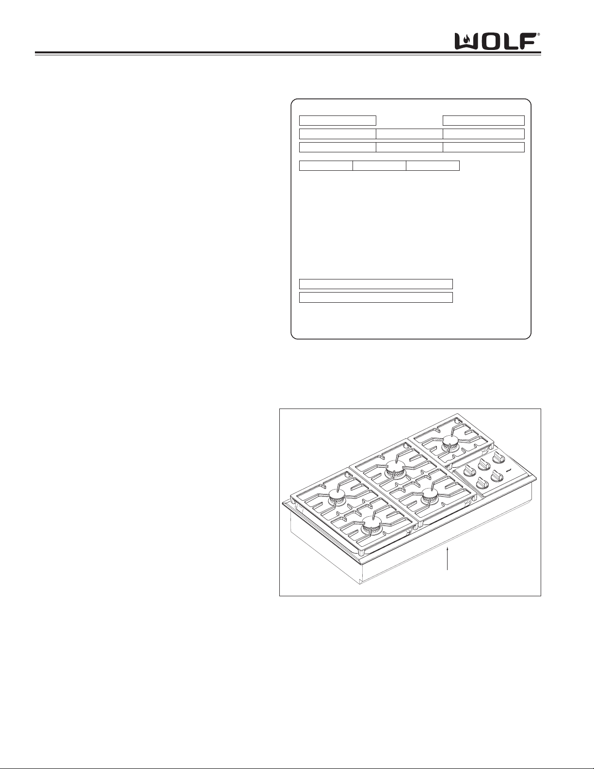
Serial Tag Location............................................................ 1-4
Model Number Key.. ......................................................... 1-5
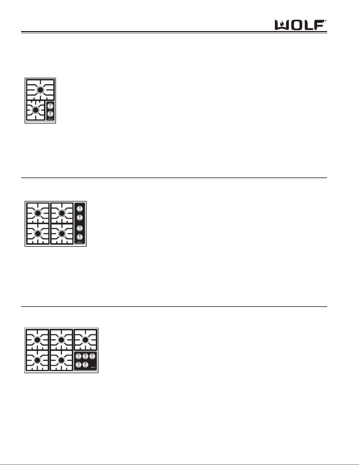
Model Configurations 15”, 30” and 36” Cooktop............... 1-6
Model Features 15”, 30” and 36” Cooktop........................ 1-7
Section 2 - Operation Information
Types of Fuel Gas............................................................. 2-2
Heating Value of Gas......................................................... 2-2
Specific Gravity of Gas...................................................... 2-2
Principles of Gas Combustion........................................... 2-3
Burner Components 15”, 30” and 36” Cooktop................. 2-4
Operation of the Wolf 15”, 30” and 36” Gas Cooktop....... 2-5
Cleaning and Maintenance................................................ 2-6
15” 30” and 36” Gas Cooktop........................................ 2-6
Section 3 - Installation Information
Electrical Requirements..................................................... 3-2
Gas Requirements............................................................. 3-3
Installation Dimensions 15” and 30” Gas Cooktop............ 3-4
Installation Dimensions 36” Gas Cooktop......................... 3-5
Installation of Multiple Units............................................... 3-5
Installation Procedures...................................................... 3-6
Filler Strip Installation Procedure....................................... 3-7
Support Kit for DownDraft Installation Procedure.............. 3-8
Section 4 - Component Access and Removal
15”, 30” and 36” Gas Cooktops
Important Warnings and Cautions..................................... 4-2
Surface Burner Components............................................. 4-3
Burner Head with Cap.................................................... 4-3
Venturi............................................................................ 4-3
Spark Electrode.............................................................. 4-4
Inner Distribution Ring.................................................... 4-4
Cooktop Pan.................................................................. 4-4
Outer Distribution Ring................................................... 4-5
Jet Holder....................................................................... 4-5
Burner Mounting Bracket............................................... 4-5
Surface Burner Orifice.................................................... 4-5
Electrical System Components......................................... 4-6
Ring Light....................................................................... 4-6
Valve Switch................................................................... 4-6
Light Harness................................................................. 4-6
Harness.......................................................................... 4-6
Spark Module................................................................. 4-7
Spark Module Support Plate.......................................... 4-7
Lead Wire....................................................................... 4-7
Power Cord with Grip..................................................... 4-7
Manifold System Components........................................... 4-8
Gas Valve....................................................................... 4-8
Gas Valve Orifice............................................................ 4-8
Gas Tubing..................................................................... 4-9
Manifold.......................................................................... 4-9
Regulator........................................................................ 4-9

General Information
1-4
GGAASSCCOOOOKKTTOOPP--
GGAASSCCOOOOKKTTOOPP--22
22SSEERRIIEESS
SSEERRIIEESS
WARRANTY INFORMATION
This page contains a summary of the 2 & 5 Year
Warranty that is supplied with every Wolf product, fol-
lowed by details and notes about the warranties.
TWO & FIVE YEAR Warranty Summary
• Two year TOTAL PRODUCT warranty, parts and
labor.
• Limited Parts Only Warranty for the 3rd through 5th
year on the following parts only:
Gas Burners (excluding appearance)
Warranty Details:
The warranty applies only to products installed for
normal residential use. The warranty applies only to
products installed in the United States or Canada.
Warranty Notes:
• All warranties begin at the time of the initial
installation.
• All Warranty and Service information collected by
Wolf Appliance Company, LLC. is arranged and
stored under the unit serial number and/or the
customer’s name. Please note that Wolf Appliance
Company, LLC. requests that you have the model
and serial number available whenever contacting
the factory or parts distributor.
• See Figure 1-1 for serial tag layout.
• See Figure 1-2 for serial tag location.
Wolf Appliance Company, LLC
FITCHBURG, WI
GAS
LEFT
REAR
LEFT
FRONT
VOLTS
CENTER
REAR
CENTER
FRONT
AMP
PRESS.
MAIN
REAR
RIGHT
FRONT
RIGHT
HERTZ
ELECTRICAL RATING
000 000 60
INPUT RATING EACH
BURNER-BTU/HR.
MODEL
NO.
SERIAL
ANSI Z21.1 2000 "HOUSEHOLD GAS COOKING APPLIANCES"
"CAN1-1.1-M81"
BD
801503
Figure 1-1 Typical Serial Tag Layout
Serial Tag Location
Figure 1-2 The serial tag is located on the bottom of the
cooktop.

General Information
1-5
GGAASSCCOOOOKKTTOOPP--
GGAASSCCOOOOKKTTOOPP--22
22SSEERRIIEESS
SSEERRIIEESS
MODEL NUMBER KEY
Refer to this key for an example of the model numbers.
Model: CT 36 G / S
Product Type
Size
Fuel
Feature (If Applicable)
Finish
Product Type
CT Cooktop
IM Integrated Gas
Multi-Function Cooktop
IG Integrated Grill Cooktop
IS Integrated Steamer Cooktop
IF Integrated Fryer Cooktop
Size (If Required)
15 15 - inch wide unit
30 30 - inch wide unit
36 36 - inch wide unit
Fuel (If Applicable)
EElectric
GNatural Gas
LP Propane Gas
Finish
SClassic Stainless Steel
PPlatinum Stainless Steel (Not Available for IM, IG, IS, IF and CT15G)
BCarbon Stainless Steel (Not available for Gas models. Not available for IM, IG, IS, IF and CT15G)
NOTE: Model number listed on serial number tag will note series of unit with a dash followed by a numeric value.

General Information
1-6
GGAASSCCOOOOKKTTOOPP--
GGAASSCCOOOOKKTTOOPP--22
22SSEERRIIEESS
SSEERRIIEESS
MODEL CONFIGURATIONS
Model Numbers Descriptions
CT30G/S Cooktop 30” Gas Stainless Steel Natural Gas
CT30G/S- LP Cooktop 30” Gas Stainless Steel Propane
CT30G/P Cooktop 30” Gas Platinum Stainless Steel Natural Gas
CT30G/P- LP Cooktop 30” Gas Platinum Stainless Steel Propane
• Four burner
• One burners at 15,000 BTU
688 BTU’S delivered at simmer
• One burners at 12,000 BTU
700 BTU’S delivered at simmer
• Two burners at 9,200 BTU
300 BTU’s delivered at simmer
30” Gas
36” Gas
Model Numbers Descriptions
CT36G/S Cooktop 36” Gas Stainless Steel Natural Gas
CT36G/S- LP Cooktop 36” Gas Stainless Steel Propane
CT36G/P Cooktop 36” Gas Platinum Stainless Steel Natural Gas
CT36G/P- LP Cooktop 36” Gas Platinum Stainless Steel Propane
• Five burner
• One burners at 15,000 BTU
688 BTU’S delivered at simmer
• One burners at 12,000 BTU
700 BTU’S delivered at simmer
• Three burners at 9,200 BTU
300 BTU’s delivered at simmer
Model Numbers Descriptions
CT15G/S Cooktop 15” Gas Stainless Steel Natural Gas
CT15G/S- LP Cooktop 15” Gas Stainless Steel Propane
• Two burner
• One burner at 12,000 BTU
700 BTU’S delivered at simmer
• One burner at 9,200 BTU
300 BTU’s delivered at simmer
15” Gas

General Information
1-7
GGAASSCCOOOOKKTTOOPP--
GGAASSCCOOOOKKTTOOPP--22
22SSEERRIIEESS
SSEERRIIEESS
MODEL CONFIGURATIONS
MODEL FEATURES for 15” Gas Cooktop-2 Series
• Simmer on all burners
• Dual stacked sealed burners
• Single spark ignition with auto reignition for all burners
• 12,000 BTU/hr and 9,200 BTU/hr burners
• Low profile, continuous, porcelain-coated cast iron grates
• Smart porting of all burners
• Back lit illuminated control panel.
• Electric ratings: 110-120V/ 15 amp circuit
• Available in Natural or LP gas
• Two and Five year warranty
MODEL FEATURES for 30” & 36” Gas Cooktop-2 Series
• Simmer on all burners
• Dual stacked sealed burners
• Single spark ignition with auto reignition for all burners
• 15,000 BTU/hr, 12,000 BTU/hr and 9,200 BTU/hr burners
• Low profile, continuous, porcelain-coated cast iron grates
• Smart porting of all burners
• Back lit illuminated control panel.
• Electric ratings: 110-120V/ 15 amp circuit
• Available in Natural or LP gas
• Two and Five year warranty

General Information
1-8
GGAASSCCOOOOKKTTOOPP--
GGAASSCCOOOOKKTTOOPP--22
22SSEERRIIEESS
SSEERRIIEESS

GGAASSCCOOOOKKTTOOPP--
GGAASSCCOOOOKKTTOOPP--22
22SSEERRIIEESS
SSEERRIIEESSOperation Information
SECTION 2
OPERATION INFORMATION
2-1

2-2
GGAASSCCOOOOKKTTOOPP--
GGAASSCCOOOOKKTTOOPP--22
22SSEERRIIEESS
SSEERRIIEESS
Operation Information
OPERATION INFORMATION
A service technician should understand how a gas appliance operates before attempting to service the appliance.
This section provides descriptions of the different types of fuel gases and explains gas heating values. A definition
of specific gravity of gas is given along with its characteristics and effects. Gas combustion principles are explained
and gas burner components are described and illustrated. The end of this section contains illustrations which
demonstrate basic cooking appliance theory of operation.
Types of Fuel Gas:
Gases used to supply heat energy are called fuel gases. Common fuel gases are not simply one kind of hydrocar-
bon, they are mixtures of hydrocarbon gases. They contain other gases as well, such as free hydrogen, carbon
dioxide and nitrogen. As an example, natural gas might contain 85% methane, 12% ethane and 3% of other gases.
The presence of each of these gases in the fuel gas has some effect on the nature of the gas.
Some common fuel gasses are methane [CH4], ethane [C2H6], Propane [C3H8] and butane [C4H10]. Propane and
butane are nearly odorless. Natural gas that is processed to remove condensables and moisture, has little or no
odor and no color. Odorants are added to natural gas before distribution to aid in leak detection. A common odorant
used is a colorless liquid containing sulfur compounds.
Heating Value of Gas:
Heat energy produced when burning a fuel gas is commonly expressed in British Thermal Units (BTU). One BTU of
heat will raise the temperature of one pound of water one degree Fahrenheit.
The more carbon and hydrogen atoms in each molecule of a fuel gas, the higher its heating value. Natural gas
which is high in methane has a heating value of about 950 to 1150 BTU per cubic foot. The variance is due to the
various other substances found in natural gases. The more ethane, propane or butane in the gas raises the heating
value. Propane, or LP gas, has a heating value of about 2500-2800 BTU per cubic foot, and butane about 3200
BTU per cubic foot.
Specific Gravity of Gas:
The specific gravity of a gas is the weight of one cubic foot, or the gas compared to one cubic foot of dry air. When
stating the specific gravity of a gas, a pressure and temperature must be clearly stated. In the gas industry, the
standard conditions of pressure and temperature are 30.0 inches of mercury and 60° F. A pressure of 30.0 inches of
mercury will sustain a column of mercury 30 inches high in a tube with a vacuum on top of the column. Since air is
used as the reference, its specific gravity is always 1.0. This value of 1.0 has no direct physical meaning with
regard to air, such as its density. It is only a relative number or ratio used to express specific gravity of other gases.
The specific gravity of a gas will determine if the gas will rise or fall when released into the air. Natural gas will rise
since its specific gravity is less than 1.0 at 0.4 to 0.8. Propane has a specific gravity of 1.5 and butane 2.0. These
gases will fall when released into the air. They sometimes collect in low spots into pools which become a hazard if
open flames are present.
In addition, specific gravity has two other characteristics. It has an important effect on the flow of gases through ori-
fices, and hence the rating of the burners. Gas flow through an orifice is dependent upon the orifice size and the
gas pressure upstream of the orifice. More of a lighter gas will flow through a given orifice size than a heavier gas
at the same gas pressure. This effect is taken into account in tables and calculators used to select orifice sizes for
burners.
Specific gravity also affects gas flow in pipes. A given driving pressure at a pipe inlet will move more lighter gas
than heavier gas through that pipe.

2-3
GGAASSCCOOOOKKTTOOPP--
GGAASSCCOOOOKKTTOOPP--22
22SSEERRIIEESS
SSEERRIIEESSOperation Information
PRINCIPLES OF GAS COMBUSTION:
Combustion - When oxygen acts with a substance to produce large amounts of heat rapidly.
Requirements for Combustion - There are three required elements for combustion to occur; Fuel (Gas), Oxygen
(Air) and Heat (Ignition Temperature, which for gas is between 1100°F/593°C and 1200°F/649°C). All must be pres-
ent. Removing any one of the three and combustion will cease.
Chemistry of Combustion - Combustion of gas is a chemical reaction between fuel gas and oxygen. The basic
elements of common fuel gasses are hydrogen [H] and carbon [C]. When hydrogen burns, water vapor [H2O] is pro-
duced. Complete burning of carbon in fuel gases form carbon dioxide [CO2] and water vapor [H2O].
Controlled Combustion - Controlled combustion takes place when gas and air are supplied at proper rates to
assure complete combustion of the gas in a steady flame. When a gas appliance is operating properly, burning
starts at the burner ports. Gas flow is controlled by gas orifice size and gas pressure upstream of the orifice. Air is
mixed with the gas before it passes through the burner ports. This added air is called “Primary Air”. The remaining
air required for complete combustion is supplied to the burner at the point of combustion and is called “Secondary
Air”.
Adjustments of the gas-to-air ratio and the secondary air supply is the key to obtaining stable blue flames at a burn-
er. Proper amounts of primary and secondary air are required for quiet and efficient burner operation and for com-
plete combustion of the gas. Air Shutters or other devices provide control of primary air. Inlet opening and flue out-
lets control Secondary Air flow.
Total air - In an ideal situation, primary and secondary air is all that is needed (for the oxygen required) to burn the
gas, but some additional air is required to assure complete burning of the gas. The total air, “primary”, “secondary”
and “excess” are expressed as percentages of the amount needed. About ten cubic feet of air is required to com-
pletely burn one cubic foot of gas. For this reason an appliance should not be operated in an air tight home.
Limits of Flammability - Not all air-to-gas mixtures will burn. Mixtures with 0% - 4% natural gas in air are too lean
to burn. Mixtures of 4% - 14% natural gas in air can burn with a controlled flame. Flammability limits come into play
when primary air adjustments are made on burners. If too much primary air is used, the mixture may become too
lean and fall below flammability limits, thus preventing combustion.
Incomplete Combustion (Causes and Effects) - To obtain complete combustion, sufficient amounts of air must be
supplied to the process. This air must have a reasonably normal oxygen content. Complete burning of gas pro-
duces harmless carbon dioxide gas and water vapor. If the air supply is insufficient, incomplete combustion occurs
resulting in the formation of toxic by-products, such as carbon monoxide [CO] or aldehydes.
Carbon monoxide is colorless and odorless. Inhaling carbon monoxide in sufficient quantities could cause death by
reducing oxygen levels in the blood.
Aldehydes, which are equally dangerous, have a sharp and penetrating odor which is easily detected by smell at
very low concentrations. The odor caused by aldehydes should not be confused with odorants added to natural gas.
The absence of aldehydes does not assure that carbon monoxide is not present. However, if the odor of aldehydes
is present, then carbon monoxide is virtually always present.
Gas Burner Operation - A gas burner is a device to burn gas under control in order to produce useful heat.
Primary air is brought into the burner from outside of the appliance at atmospheric pressure. The gas jet streaming
from the orifice draws primary air with it into the burner.
The gas/air mixture, combined with a spark at the burner port(s) and the secondary air creates a controlled burn.

2-4
GGAASSCCOOOOKKTTOOPP--
GGAASSCCOOOOKKTTOOPP--22
22SSEERRIIEESS
SSEERRIIEESS
Operation Information
BURNER COMPONENTS for 15”, 30” and 36”
Burner Head - The component containing the burner ports where the gas/air mixture ignites. The burner ports are
distributed in a useful pattern to optimize heat transfer. The flames should be spread so they can be easily reached
by secondary air and provide a stable blue flame.
Venturi - Threaded brass pipe that threads into the jet holder through the distribution rings which narrows and then
flares out again. This pipe helps maintain proper and constant primary air injection.
Inner Distribution Ring - Routes the gas from the simmer orifice hood to the simmer port holes located on the
burner cap.
Outer distribution Ring - Routes the gas from the main burner orifice hood to the main burner port holes on the top
of the burner head.
Jet Holder - This component is mounted to the burner mounting bracket and to the burner box. The main burner
orifice is threaded into the jet holder as well as the venturi. It is the main support for the burner components.
Gas Orifice - An opening or hole which regulates or limits the amount of gas flowing to a burner. Gas flow rate (vol-
ume) depends on the size of the orifice (hole) and the gas pressure at the inlet of the orifice.
Burner Head
Venturi
Inner Distribution Ring
Outer Distribution Ring
Jet Holder
with Connector and Orifice
with Orifice
Fig. 2-1. 15”, 30” and 36” Burner Components

GGAASSCCOOOOKKTTOOPP--
GGAASSCCOOOOKKTTOOPP--22
22SSEERRIIEESS
SSEERRIIEESS
OPERATION OF THE 15”, 30” and 36” WOLF GAS COOKTOP
Surface Burners
A spark electrode ignites each surface burner. This control eliminates the need for continuous open flame pilots.
For added safety and convenience, each burner is designed with an electronic re-ignition system. This feature
enables any burner to automatically re-light in the event it is accidentally extinguished.
This cooktop has a unique dual stacked burner design that combines all the burner parts in one configuration. A
15K burner providing 15,000 Btu/hr rating on HIGH, Large burners providing a 12,000 Btu/hr rating on HIGH and a
small burner providing 9,200 Btu/hr rating on HIGH. All burners have simmer settings.
A distinguishing feature of Wolf’s low Btu/hr control is its constant, low heat output without continuous ignitions.
Flame diameter remains full size, only the heat output is lowered. This is the ultimate control for simmering food.
After removing burner parts for any reason, it is extremely important that the burners are re-assembled correctly.
The burner cap has a special orientation and should be seated flatly. Rotate burner cap until you feel it drop and
click into position.
This patent pending dual stacked burner configuration makes it possible to enjoy cooking at full flame as well as
maintaining control while simmering at the lowest flame setting.
Grate Placement
Low profile cast iron grates are designed for a close fit. This enables pans to move easily from one burner to anoth-
er without having to lift the pan or have it tip over between the grates. Each grate sets securely on dimples on each
corner of the cooktop pan. Continuous grates are interchangeable with the exception of the single grate.
Control Knobs
Each knob is positioned to correspond to the burner regulated. For the 36-inch cooktop, the knob on the lower left
side regulates the lower left burner. Conversely, the knob on the upper right side regulates the upper right burner.
Each knob on the 30-inch cooktop control panel has a diagram above it. The diagram shows which knob to regu-
late.
It is normal for the knobs to be slightly elevated above the control panel surface. This space is an air inlet neces-
sary for good combustion of gas. Each knob rests on a valve stem with a rubber grommet at the base. This design
prevents liquid spills from dripping into the controls below the burners.
Burner Lighting
Each burner has full flame and full simmer capabilities. Knobs are designed as a two- tiered, “push-to-turn” knob.
One tier is used for HIGH through LOW flame settings. The second tier controls SIMMER settings.
Push down and turn the corresponding control knob counter clockwise to the HIGH setting. You will hear “clicking”
and see the burner ignite. Once the burner is lit, continue turning the knob counter clockwise to any one of the set-
tings, HIGH through LOW.
To select a simmer setting, turn the knob to the LOW setting. You will feel a stop-detente in the knob rotation. Push
down on the knob, continuing to turn it counter clockwise. This moves it to the second tier. Now, select any varia-
tion within the SIMMER flame settings, HIGH through LOW.
Illuminated Control Panel
This unique feature of the cooktop is an instant visual indicator that one or more burners are in use. It is also a
safety signal reminder that a flame is on and active.
Operation Information
2-5

GGAASSCCOOOOKKTTOOPP--
GGAASSCCOOOOKKTTOOPP--22
22SSEERRIIEESS
SSEERRIIEESS
Operation Information
2-6
Burner Spill Tray
Exterior Finish
Burner Cap
Burner Grates
Control Knobs
Control Panel
Spark Igniters
Part Identification
CLEANING and MAINTENANCE
Material Care Recommendation
Stainless steel
Although resistant to most
stains, it is not totally impervi-
ous to damage. Salt and
some cooking liquids may pit
and stain surface. Always
remove these spills immediate-
ly.
Avoid using abrasive cleaners;
they will permanently scratch
the surface.
Porcelain enamel (matte finish)
Never wipe a warm or hot
porcelain surface with a damp
sponge; it may cause chipping
or crazing (tiny hair-like cracks)
Porcelain-coated cast iron
Chrome-plated
Tempered glass
Ceramic
General care: Use a clean cloth or sponge, wipe
with warm water and mild detergent. Rinse and
dry immediately. Apply protective polish, always in
the same direction.
Spray degreaser: Removes fingerprints and
greasy spatters. Spray on a cloth and wipe sur-
face. Buff dry immediately to avoid streaking.
Protective polish: Apply to surface to maintain lus-
ter and protect from some food stains
Hard water stains: Use white vinegar and water.
Cool first. Wash in warm water with liquid deter-
gent or mild abrasive cleaners.
Foods high in acid or sugar content, such as milk,
tomatoes, sauerkraut, fruit juices and pie filling,
may pit or craze the surface. Remove as soon as
possible. Do not cook the spill on again.
Remove from cooktop and place on a flat surface
near the sink.
Non-abrasive cleaners: Hot water and liquid deter-
gent, paste of baking soda and water, plastic pad
or sponge.
Mild abrasive and abrasive cleaners: Use sparing-
ly.
To remove the knobs, slip the edge of a dishtowel
under the knob; pull the edge together. Using the
towel for leverage, lift up; the knob pulls off of the
valve stem.
General care: Wipe each knob with a damp cloth
and mild soap and water; rinse and dry. Never
soak or use abrasive cleaners; they will scratch the
finish and remove the markings.
Spray cleaners: Removes fingerprints and greasy
food soils. Spray first on a cloth before wiping
panel.
Keep dry Never spray water or cleaner directly on
the igniter. When cleaning around the surface
burner, be careful that the cloth does not catch on
the igniter and damage it.

GGAASSCCOOOOKKTTOOPP--
GGAASSCCOOOOKKTTOOPP--22
22SSEERRIIEESS
SSEERRIIEESSInstallation Information
SECTION 3
INSTALLATION
INFORMATION
3-1

3-2
GGAASSCCOOOOKKTTOOPP--
GGAASSCCOOOOKKTTOOPP--22
22SSEERRIIEESS
SSEERRIIEESS
Installation Information
INSTALLATION INFORMATION
This section of the manual covers some of the installation issues that a service technician may need to know when
servicing a Wolf Gas Cooktop. If additional installation information is needed after reviewing this section of the man-
ual, please refer to the Installation Guide or contact the Wolf Appliance Customer Service Department.
Electrical Requirements:
•110-120 volts AC, 60 Hertz, 15 ampere fused electrical supply.
•A timed-delay fuse or circuit breaker is recommended.
•Separate circuit serving only this appliance.
•Installation site must be equipped with a properly grounded 3-prong receptacle.
This appliance when installed must be properly grounded. This appliance is equipped with a 3-prong (grounding)
plug. The power cord must be plugged into a mating 3-prong ground-type receptacle. (See Figure 3-1).
If a mating receptacle is not available, it is the obligation of the customer to have a properly grounded, 3-prong
receptacle installed by a qualified electrician.
If the electric receptacle or the power cord are not properly grounded and polarized, a shock hazard could exist and
the appliance may experience ignition problems.
A SHOCK HAZARD COULD EXIST IF THE ELEC-
TRIC RECEPTACLE OR THE POWER CORD ARE
NOT PROPERLY GROUNDED AND POLARIZED.
Fig. 3-1. Proper Polarity at Electric Receptacle
Grounding Type
Wall Receptacle
Neutral
Ground
Line
Voltage
(Power)
TO AVOID SHOCK HAZARD, NEVER REMOVE THE
GROUNDING PRONG FROM THE PLUG OF THE
POWER SUPPLY CORD.
The appliance may experience ignition problems if
not properly grounded and polarized.

3-3
GGAASSCCOOOOKKTTOOPP--
GGAASSCCOOOOKKTTOOPP--22
22SSEERRIIEESS
SSEERRIIEESSInstallation Information
Gas Requirements:
NOTE: All Wolf gas appliances are manufactured to
work with natural gas or LP gas (Liquid Propane gas).
Natural Gas Manifold Pressure
Standard natural gas orifices on the appliance are set
for 5” WC (Water Column Pressure).
Liquid Propane Manifold Pressure
The standard propane gas orifices on the appliance are
set for 10” WC (Water Column Pressure).
Gas Supply Line Size
• 1/2 inch
Gas Supply Pressure
•Maximum line pressure for natural gas and LP is
14” WC; 1/2 psi (3.5 kPa).
•Minimum line pressure for natural gas is 7” WC.
•Minimum line pressure for LP gas is 11” WC.
Gas Pressure Regulator
To control and maintain a uniform gas pressure in the
gas manifold, Wolf gas appliances must be connected
to the gas supply line through a pressure regulator.
The burner orifices are sized for the pressure delivered
by the regulator. Never attempt to operate a Wolf gas
appliance without the use of the proper pressure
regulator.
Gas Shut-off Valve
The supply line must be equipped with an approved
shut-off valve. This valve should be located in accor-
dance to all national, local codes and ordinances.
(See Figure 3-2).
Leak Testing
NEVER USE OPEN FLAMES TO CHECK FOR GAS
LEAKS. ONLY USE A LEAK TESTING SOLUTION
OF SOAPY WATER OR AN ELECTRONIC LEAK
DETECTOR. DO NOT USE LIQUID NEAR VALVE
STEMS.
The maximum gas supply pressure to the regulator
should never exceed 14” WC (Water Column
Pressure); 1/2 psi (3.5kPa)
Shut-off Valve
(open position)
To Cooktop
Gas Supply Line
Fig. 3-2. Shut-off Valve

3-4
GGAASSCCOOOOKKTTOOPP--
GGAASSCCOOOOKKTTOOPP--22
22SSEERRIIEESS
SSEERRIIEESS
Installation Information
15” AND 30” GAS COOKTOP INSTALLATION DIMENSIONS
Area Requirements:
Note: Countertop opening dimensions that are shown must be used. Given dimensions provide required clear-
ances.
E
21/2" min
(6.4)
15"
(38.1)
15"
(38.1)
14"*
(35.6)
4"
(10.2)
5"
(12.7)
G
* Dimensions may vary
by ± 1/8" (.3 cm)
13"
(33.0)
24" or 30"***
18"**
(45.7)
Combined width
of all cooktops
(61.0 or 76.2)
to cooking surface
7"
(17.8)
7"
(17.8)
"*
19
1/4
(49.0)
** 18” (45.7cm) minimum clearance upper cabinet to countertop within 7” (17.8cm) minimum side clearance to
combustible surface above countertop.
*** 24” (61cm) minimum clearance between top of cooking surface and bottom of wood or metal cabinet which is
protected by not less than 1/4” (.6cm) flame retardant millboard covered with not less than No. 28 MSG sheet
steel, .015” (.04cm) stainless steel, or .024” (.06cm) aluminum or .02” (.05cm) copper.
*** 30” (76.2) minimum clearance between top of cooking surface and bottom of an unprotected wood or metal
cabinet.
Note: Do not seal cooktop to countertop.
Fig. 3-3. 15” Installation Dimensions
E
31/2"
(8.9)
10"
(25.4)
4"
(10.2)
10"
(25.4)
29"*
(73.7)
191/4"*
(48.9)
21/2"
min
(6.4) 31/2"min
(8.9)
30" oven cutout location
43/4"min
(12.1)
E
G
* Dimensions may vary
by ± 1/8" (.3 cm)
30"
(76.2)
13"
(33.0)
24" or 30"***
(61.0 or 76.2)
18"**
(45.7)
to cooking surface
Fig. 3-4. 30” Installation Dimensions
Other manuals for 2 Series
1
This manual suits for next models
3
Table of contents
Other Wolf Cooktop manuals

Wolf
Wolf CT15I/S Instructions for use

Wolf
Wolf GAS COOK TOPS User manual

Wolf
Wolf CT15I/S User manual

Wolf
Wolf CT30EU Instructions for use

Wolf
Wolf ICBGC152T/S User manual

Wolf
Wolf SB13 User manual

Wolf
Wolf CI365C/B User manual

Wolf
Wolf CG Series User manual

Wolf
Wolf CI243C/B User manual

Wolf
Wolf Gas cooktop User manual

Wolf
Wolf CG Series User manual

Wolf
Wolf CT30I/S User manual

Wolf
Wolf ICBIM15G User manual

Wolf
Wolf ICBGC152T/S User manual

Wolf
Wolf CT15G-3 User manual

Wolf
Wolf CT30I/S User manual

Wolf
Wolf CT30I/S User manual

Wolf
Wolf CE152TF/S Operating manual

Wolf
Wolf CT15G-2 Operating manual

Wolf
Wolf ICBMM15TF/S/LP User manual