wolfappliance.com
|
3
ESPECIFICACIONES
Suministro de gas
La instalación debe cumplir las ordenanzas y normativas
nacionales.
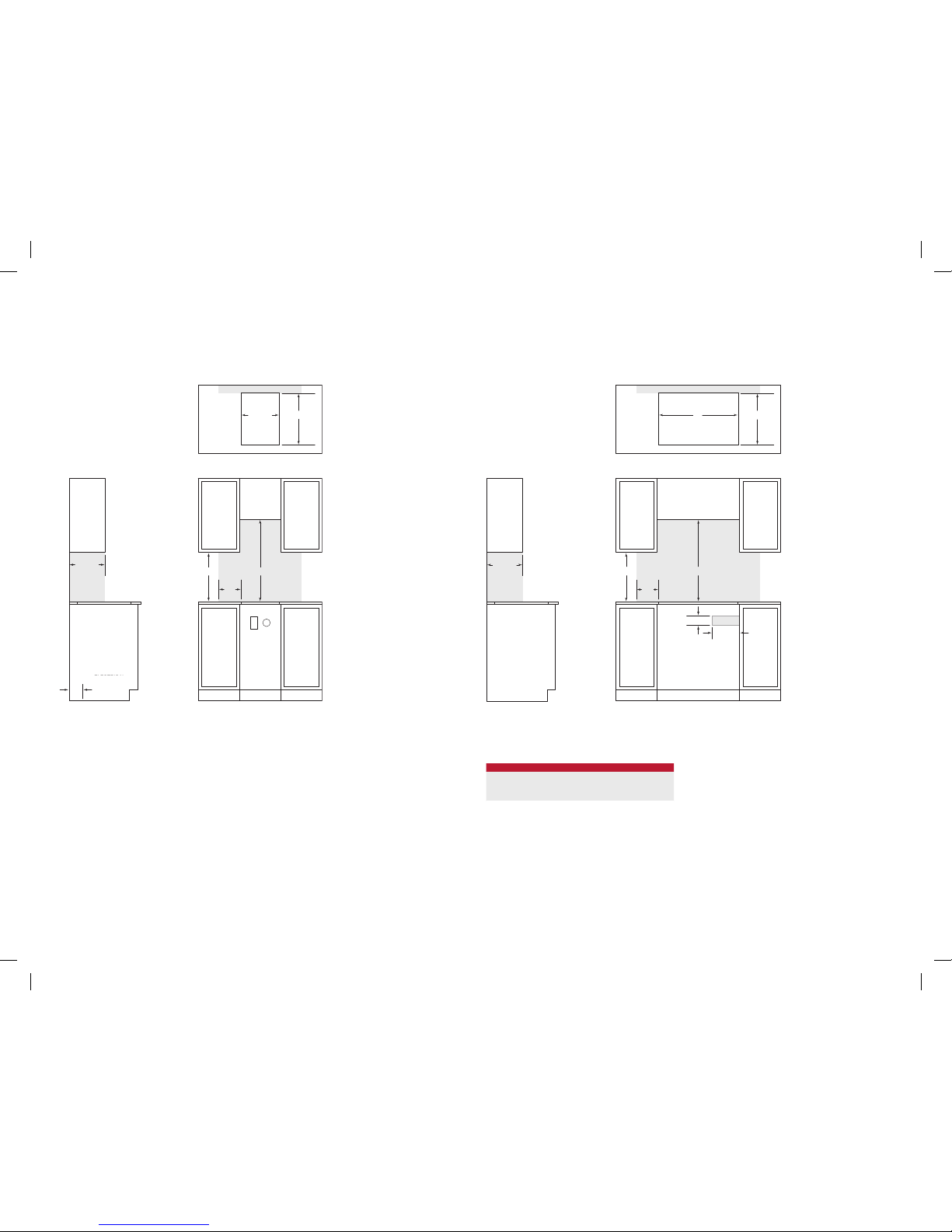
Ubique la toma de gas tal como se muestra en las ilustra-
ciones de la página 4.
La placa de gas está equipada para usarse con gas natural
o gas propano líquido (GPL). Podrá encontrar información
sobre el tipo de gas que debería utilizar en la placa de datos
del producto. Consulte la siguiente ilustración para ver la
ubicación de la placa. Si esta información no coincide con
el tipo de gas que tiene disponible, póngase en contacto
con su proveedor de gas.
Antes de llevar a cabo la instalación, asegúrese de que las
condiciones de distribución locales (tipo y presión del gas)
y el ajuste del aparato son compatibles. Las condiciones
de ajuste de este aparato se especican en la etiqueta (o
en la placa de datos del producto). La placa de datos está
ubicada en la parte inferior del aparato.
Este aparato no está conectado a ningún dispositivo de
evacuación de productos de combustión. El aparato debe
instalarse y conectarse siguiendo las normativas de instala-
ción vigentes. Debe prestar especial atención a los requi-
sitos relevantes correspondientes a la ventilación.
REQUISITOS DEL SUMINISTRO DE GAS
GAS NATURAL
Presión del suministro de gas 12,5 mb
Presión mínima 17,5 mb
Presión máxima al regulador 100 mb
GAS LP
Presión del suministro de gas 25 mb
Presión mínima 27,4 mb
Presión máxima al regulador 100 mb
CLASIFICACIÓN DEL GAS
MODELO
PRODUCCIÓN
DE CALOR
TOTAL
UNIDADES
DE GAS
CATEGORÍA
DEL APARATO
TIPOS Y PRESIÓN
(mbar) PAÍS DE DESTINO
ICBGC152T/S 6,2 kW
I2H G20 a 20 AT, BG, CR, CZ, DK, EE, FI, GR, HR, HU, IS, IE, IT, LV,
LT, NO, PT, RO, SK, SI, ES, SE, CH, TR, GB
I2E G20 a 20 DE, LU, PL
I2E+ G20 a 20/25 BE, FR
ICBCG152T/S/LP 1594 g/h I3P G31 a 37 FI, CR, GR, IE, HR, LU, NL, PL, SK, SI, ES, CH, TR, GB
ICBCG304T/S 14,2 kW
I2H G20 a 20 AT, BG, CR, CZ, DK, EE, FI, GR, HR, HU, IS, IE, IT, LV,
LT, NO, PT, RO, SK, SI, ES, SE, CH, TR, GB
I2E G20 a 20 DE, LU, PL
I2E+ G20 a 20/25 BE, FR
ICBCG304T/S/LP 3651 g/h I3P G31 a 37 FI, CR, GR, IE, HR, LU, NL, PL, SK, SI, ES, CH, TR, GB
ICBCG304P/S 14,2 kW
I2H G20 a 20 AT, BG, CR, CZ, DK, EE, FI, GR, HR, HU, IS, IE, IT, LV,
LT, NO, PT, RO, SK, SI, ES, SE, CH, TR, GB
I2E G20 a 20 DE, LU, PL
I2E+ G20 a 20/25 BE, FR
ICBCG304P/S/LP 3651 g/h I3P G31 a 37 FI, CR, GR, IE, HR, LU, NL, PL, SK, SI, ES, CH, TR, GB
ICBCG365T/S 16,9 kW
I2H G20 a 20 AT, BG, CR, CZ, DK, EE, FI, GR, HR, HU, IS, IE, IT, LV,
LT, NO, PT, RO, SK, SI, ES, SE, CH, TR, GB
I2E G20 a 20 DE, LU, PL
I2E+ G20 a 20/25 BE, FR
ICBCG365T/S/LP 4345 g/h I3P G31 a 37 FI, CR, GR, IE, HR, LU, NL, PL, SK, SI, ES, CH, TR, GB
ICBCG365P/S 16,9 kW
I2H G20 a 20 AT, BG, CR, CZ, DK, EE, FI, GR, HR, HU, IS, IE, IT, LV,
LT, NO, PT, RO, SK, SI, ES, SE, CH, TR, GB
I2E G20 a 20 DE, LU, PL
I2E+ G20 a 20/25 BE, FR
ICBCG365P/S/LP 4345 g/h I3P G31 a 37 FI, CR, GR, IE, HR, LU, NL, PL, SK, SI, ES, CH, TR, GB
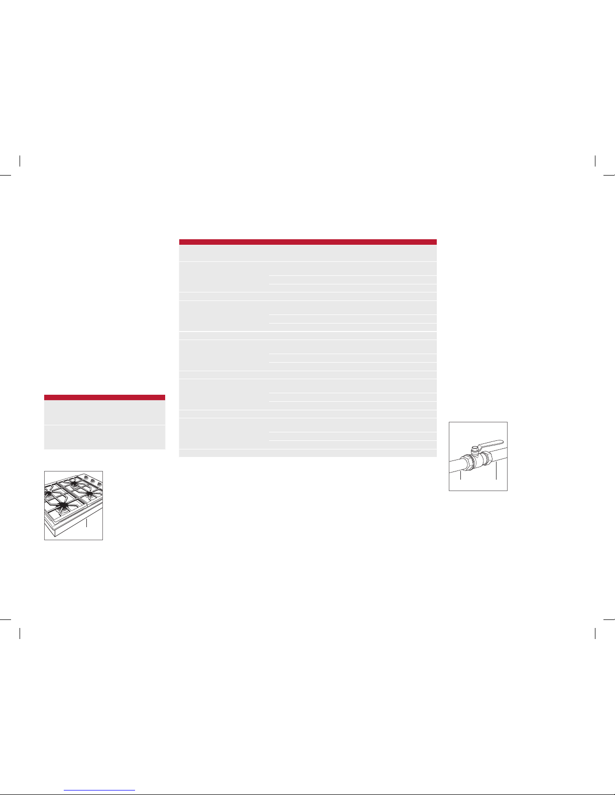
La placa debe conectarse a un suministro de gas regulado.
El suministro de gas debe estar equipado con una válvula
de cierre externa de gas homologada situada en un lugar
accesible, cerca de la placa. No obstruya el acceso a la
válvula de cierre. Consulte la siguiente ilustración.
Debe conectar la placa a un suministro de gas con una
tubería rígida de 19 mm. Si las normativas locales lo per-
miten, se recomienda utilizar un conector metálico exible
certicado de 0,9 mm y 13 mm o 19 mm de diámetro
interno para conectar la entrada macho 1/2" NPT (o ISO
7/1-14) de las unidades al suministro de gas. Debe utilizar
una pasta de recubrimiento para tuberías que sea adecuada
para que se pueda utilizar con gas LP o natural.
El aparato y su válvula de cierra deben estar desconec-
tados del sistema de suministro de gas durante cualquier
prueba de la presión del sistema que supere los 100 mbar.
El aparato debe aislarse del sistema de suministro de gas
cerrando su válvula manual de cierre individual durante
cualquier prueba de la presión del sistema que sea igual o
inferior a 100 mbar.
Las placas de gas natural Wolf funcionarán en hasta 3124 m
de altitud sin necesidad de ajuste y las placas de gas LP, en
hasta 2621 m. Si la instalación supera estas cifras, pón-
gase en contacto con su distribuidor Wolf autorizado para
obtener un kit de conversión para altitudes elevadas.
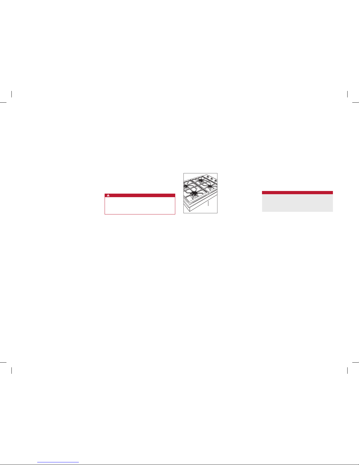
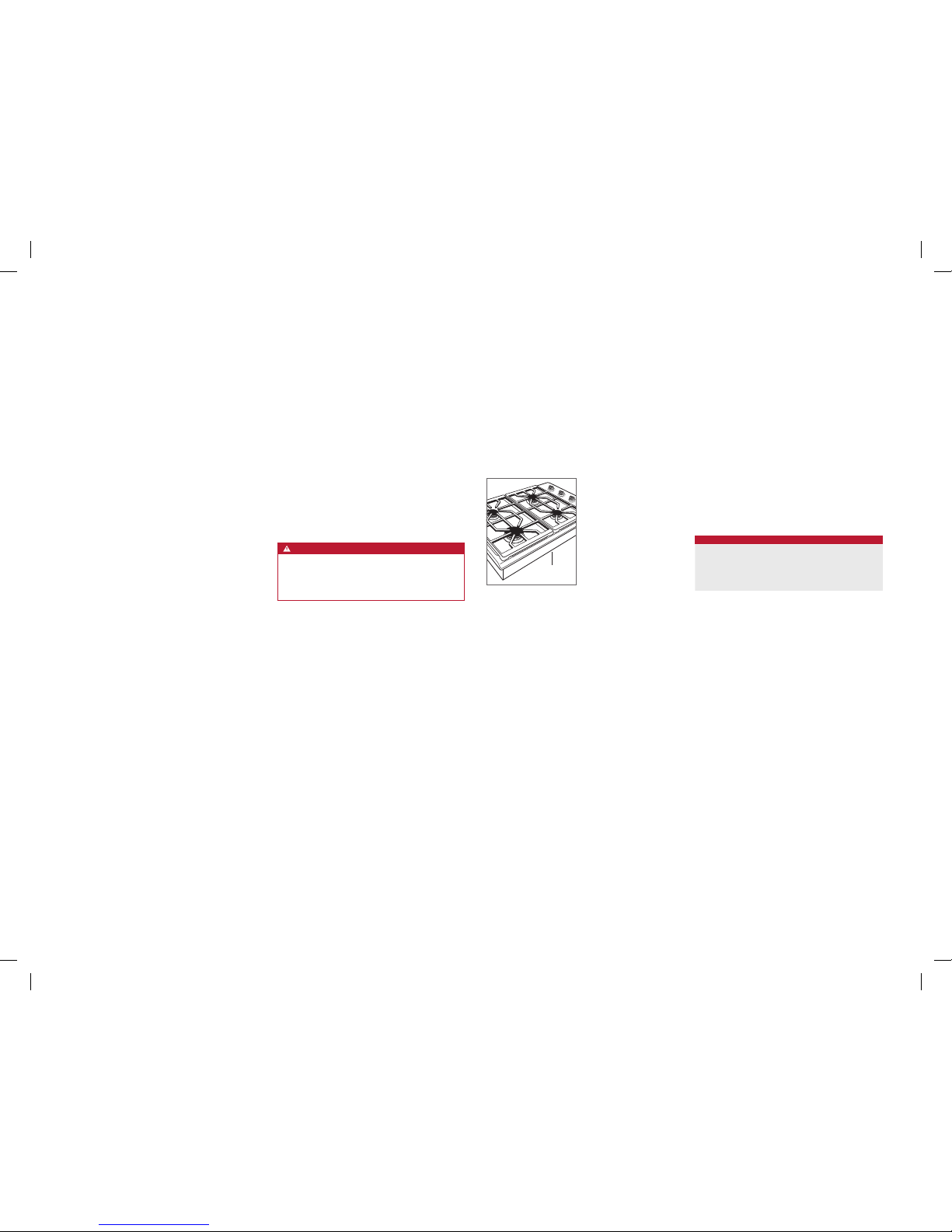
Ubicación de la placa de datos.
PLACA DE DATOS
SHUT-OFF VALVE
OPEN POSITION
GAS SUPPLYTO APPLIANCE
Válvula de cierre del gas.
SUMINISTRO
DE GAS
AL APARATO
POSICIÓN ABIERTA DE
LA VÁLVULA DE CIERRE
WF Intl GCooktops IG MultiLang 824551A 10-13.indd 3 2/19/14 12:08 PM