Wolf ICBCG15 User manual

GAS COOKTOPS
INSTALLATION INSTRUCTIONS
Model numbers
ICBCG365
This cooktop is approved for use with
Leave instructions with the owner.
COOKTOPS installation manual:Intl Gas Cooktops Install 31/3/10 2:24 PM Page 1
ICBCG15
ICBCG304
Natural Gas & Propane Gas.

As you follow these instructions, you will
notice WARNING and CAUTION symbols.
This blocked information is important for the
safe and efficient installation of Wolf equip-
ment. There are two types of potential
hazards that may occur during installation.
Another footnote we would like to identify is
IMPORTANT NOTE: This highlights informa-
tion that is especially relevant to a problem-
free installation.
signals a situation where minor injury or
product damage may occur if you do not
follow instructions.
states a hazard that may cause serious
injury or death if precautions are not
followed.
WOLF®is a registered trademark of Wolf Appliance, Inc.
COOKTOPS installation manual:Intl Gas Cooktops Install 31/3/10 2:24 PM Page 2
CONTACT
INFORMATION
Sub-Zero Group Australia Pty Ltd
Level 10, 469 La Trobe Street
Melbourne Victoria 3000
Phone 03 9600 2218
subzero-wolf.com.au

3
INS TALL AT IONR E QUIREME N T S
WHAT TO DO IF YOUSMELLGAS:
Do not try to lightany appliance.
Do not touch any electrical switch.
Do not use any phone in your
building.
Immediately callyourgassupplier
from a neighbor’s phone. Follow the
gas supplier’s instructions.
If you cannot reach yourgas
supplier, call the fire department.
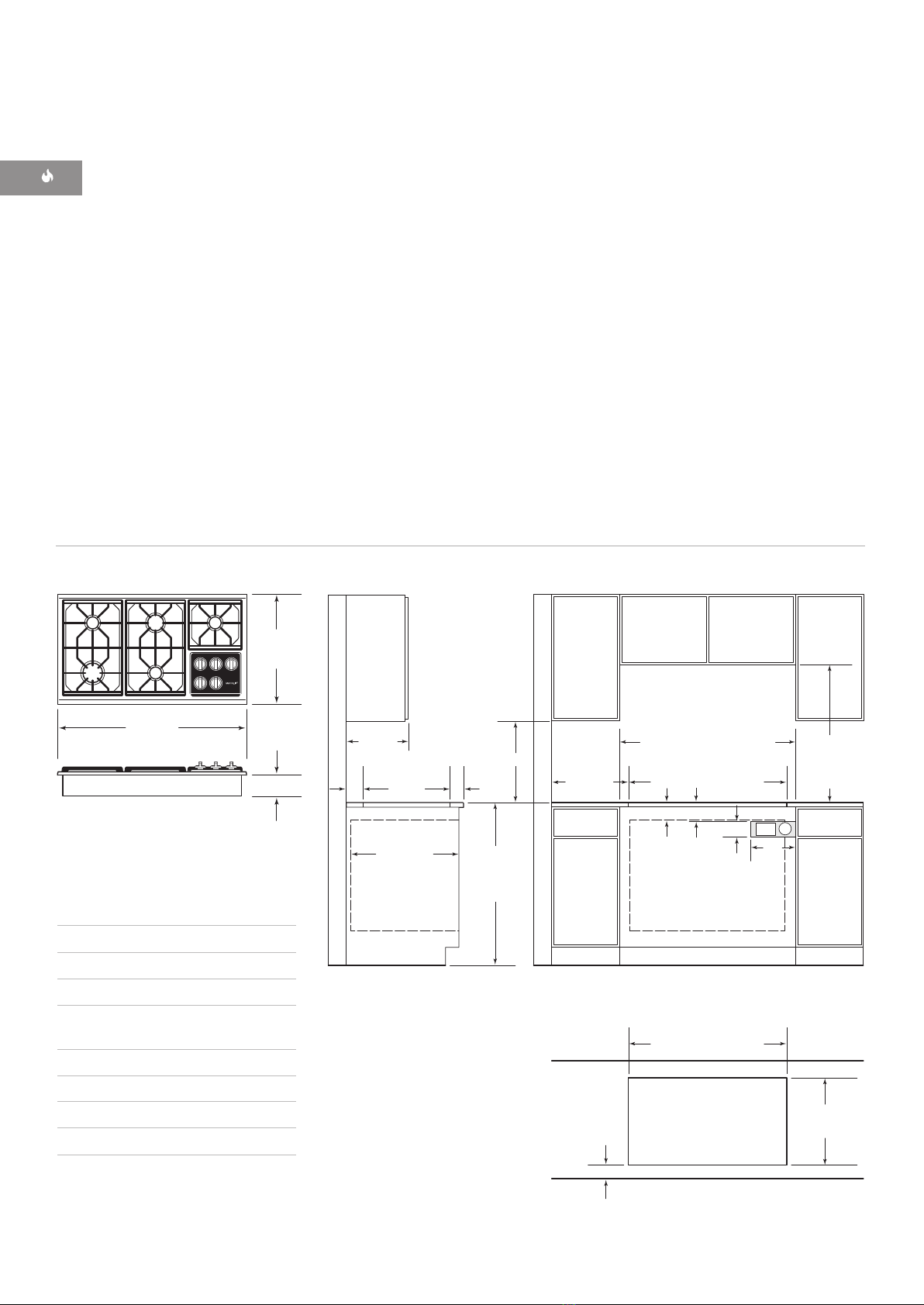
W O L F G A S COO K T O P S
Installation to be carried out only
by an authorised person.
Do not modify this appliance.
A ventilationhood is recom-
mended for use with the Wolf gas
multi-function cooktop.
Do not store or use gasoline or
otherflammablevaporsand
liquids in the vicinity of this or any
otherappliance.
The use ofagas cookingappliance
results in the production of heat
and moisture in the room in which
it is installed. Ensure that the
kitchen is well ventilated; keep
natural ventilationholesopen or
install a mechanical ventilation
device (mechanical extractor
hood).
Prolonged intensive use of the
appliance may for additional venti-
lation, for example opening of a
window, or more effective ventila-
tion, for example increasing the
level of mechanical ventilation
where present.
This appliance shallbeinstalled
in accordancewiththeregula-
tions in force and only used in a
well ventilated space. Read the
instructionsbeforeinstalling or
using this appliance.
Installer:Pleaseread the entire
InstallationInstructionsprior to
installation. Savethese instructions
for the local inspector’s reference,
then leave them with the home-
owner.
Homeowner:Please read andkeep
theseinstructions for future refer-
enceand be sure to read the entire
Use&Care Informationprior to use.
IMPORTANTNOTE:
COOKTOPS installation manual:Intl Gas Cooktops Install 31/3/10 2:24 PM Page 3
Statutory requirements: This appliance shall
be installed in accordance with the manufacturer’s
installation instructions, local gas fitting
regulations and authority, municipal building codes,
electrical wiring regulations, and AS/NZ5601 the
Australian Standard for gas installations. Refer
also to AS/NZ5601 for gas pipe sizing tables.
Not suitable for use in marine craft, caravans or mobile
homes, unless each burner is fitted with a flame
safeguard.

4
BEFORE Y O U S T A R T
Proper installation is your responsibility.
Have a qualified person install this cooktop.
You must also assure that electrical installa-
tion is adequate and in compliance with all
local codes and ordinances.
Prior to installation, ensure that the local
distribution conditions (nature of the gas
and gas pressure) and the adjustment of
the appliance are compatible.
Proper gas supply connection must be
available; refer to Gas Supply Requirements
on page 10. Electrical ground is required;
see Electrical Requirements on page 11.
The adjustment conditions for this appli-
ance are stated on the label (or rating
plate). The data plate can be found on the
underside of the cooktop.
W O L F GAS COOKTOPS
Rating plate location
Location of rating
plate under cooktop
RATING PLATE
INFORMATION
Model Number
Serial Number
IMPORTANT NOTE:
This manual covers installation instructions
for three cooktop models. i.e.:
2 burner cooktop - model ICBCG15
4 burner cooktop - model ICBCTG304
5 burner cooktop - model ICBCG365
COOKTOPS installation manual:Intl Gas Cooktops Install 31/3/10 2:24 PM Page 4

5
I N S TA L L AT I O N INSTRUCTIONS
L O C A T I O N R E Q U I R E M E N T S
Illustrations on the following pages provide the
overall dimensions, countertop cut-out and
installation specifications for Wolf gas
cooktops. Maintain the following minimum
installation dimensions:
Minimum horizontal clearance from the
sides and back of the cooktop cut-out to
adjacent vertical combustible construction,
extending a minimum of 457 mm above the
countertop, is as follows: 178 mm from side
edges of cut-out for the 381 mm cooktop;
229 mm from side edges of cut-out for the
762 mm and 914 mm cooktops; 64 mm
from rear edge of cut-out.
Minimum vertical distance between the
countertop and combustible materials
above the cooktop must be 762 mm.
Maximum 330 mm depth of overhead side
cabinets directly above and within side
clearance.
IMPORTANT NOTE:
When installing a ventila-
tion hood, refer to the specific requirements
of the hood for the minimum dimension to
countertop.
BEFORE Y O U S T A R T
Check the location where the cooktop will
be installed. The location should be away
from strong draft areas, such as windows,
doors and strong heating vents or fans. Do
not obstruct flow of combustion and
ventilation air.
This appliance is not connected to a
combustion products evacuation device. It
shall be installed and connected in accor-
dance with current installation regulations.
Particular attention shall be given to the
relevant requirements regarding ventilation.
SITE P R E P A R A T I O N
COUNTERTOP CUT-OUT
D I M E N S I O N S
IMPORTANT NOTE:
Countertop opening
dimensions shown on the following pages
must be used. The dimensions shown provide
for required clearances.
These cooktops are designed to fit a standard
610 mm deep base cabinet with a 635 mm
deep countertop. Before making the counter-
top cut-out, verify that the cooktop will clear
the side walls of the base cabinet below. There
should be at least 140 mm clearance between
the countertop and any combustible surface
directly below the unit.
IMPORTANT NOTE:
Do not seal the cooktop
to the countertop. It must be removed if
service is necessary.
Failure to locate the cooktop without the
proper clearances will result in a fire
hazard.
This cooktop is intended for indoor use.
COOKTOPS installation manual:Intl Gas Cooktops Install 31/3/10 2:24 PM Page 5

6
INSTALLATION SPECIFICATIONS
The illustrations below provide the overall
dimensions, countertop cut-out and installation
specifications for Model ICBCG15G
For Model ICBCG15 , the gas service may be
supplied through the floor if the cooktop is not
installed above an oven. Refer to the illustration
for specifics on placement of gas and electrical.
E
102 mm
G
381 mm
381 mm
381
mm
LOCATION OF GAS SUPPLY
MAY ALSO EXTEND 127 mm ON
FLOOR FROM BACK WALL
178 mm*min
CUT-OUT TO
COMBUSTIBLE
MATERIALS
(BOTH SIDES)
356 mm
COOKTOP CUT-OUT
WIDTH
356 mm
COOKTOP CUT-OUT
WIDTH
838 mm
RECOMMENDED
CABINET WIDTH
457 mm
N
OTE: Application shown allows for installation of two 381 mm modules side-by-side with 838 mm recommended cabinet width. 457 mm
recommended
cabinet width for installation of single 381 mm cooktop or module. *Minimum clearance from both side edges of cooktop cut-out
to
combustible materials up to 457 mm above countertop. **Minimum clearance from rear edge of cooktop cut-out to combustible materials up
to
457 mm above countertop.
495 mm
COOKTOP CUT-OUT
DEPTH
64 mm
min
914 mm
STANDARD
FLOOR TO
COUNTERTOP
HEIGHT
330 mm
max 762 mm
COUNTERTOP T
O
COMBUSTIBLE
MATERIALS
ABOVE COOKT
OP
64**
mm
127
mm
LOCATION OF GAS
SUPPLY MAY ALSO
EXTEND 127 mm ON
FLOOR FROM BACK WALL
FRONT OF COUNTERTOP
64 mm
min
495 mm
COOKTOP
CUT-OUT DEPTH
W O L F GAS COOKTOPS
Overall Dimensions
Countertop Cut-Out
381 mm
OVERALL WIDTH
533 mm
OVERALL
DEPTH
102 mm
MODEL ICBCG15
DIMENSIONS
Overall Width 381 mm
Overall Height 102 mm
Overall Depth 533 mm
Recommended
Cabinet Width 838 mm
Minimum Cabinet Depth 578 mm
Minimum Height Clearance 102 mm
Cut-Out Width 356 mm
Cut-Out Depth 495 mm
Unit dimensions may vary to ±3 mm.
INSTALLATION SPECIFICATIONS – MODEL ICBCT15G/S
IMPORTANT NOTE:
When multiple cooktop
units are installed side by side, refer to the
countertop cut-out dimensions on page 9.
533 mm
OVERALL
DEPTH
381 mm
OVERALL
WIDTH
102 mm Note A
Note B
Note A:
Side clearances. If the distance
measured from the periphery of the
nearest burner to any vertical surface
is less than 200 mm, the surface shall
be protected in accordance of
AS/NZ5601.
Note B:
The rangehood fitted above the
cooktop must be installed according
to the installation instructions for
the rangehood. A minimum
distance of 600 mm is required for a
range hood and 750 mm for an
exhaust fan.
COOKTOPS installation manual:Intl Gas Cooktops Install 31/3/10 2:24 PM Page 6

7
INSTALLATION INSTRUCTIONS
229 mm*min
CUT-OUT TO
COMBUSTIBLE
MATERIALS
(BOTH SIDES)
457 mm
495 mm
COOKTOP CUT-OUT
DEPTH
914 mm
STANDARD
FLOOR TO
COUNTERTOP
HEIGHT
330 mm
max 762 mm
COUNTERTOP T
O
COMBUSTIBLE
MATERIALS
ABOVE COOKT
OP
610 mm min
*
Minimum clearance from both side edges of cooktop cut-out to combustible materials up to 457 mm above countertop.
*
*Minimum clearance from rear edge of cooktop cut-out to combustible materials up to 457 mm above countertop.
102 mm
254
mm
89 mm E
95 mm
min
G
762 mm OVEN OPENING
737 mm COOKTOP
CUT-OUT WIDTH
737 mm
COOKTOP CUT-OUT WIDTH
FRONT OF COUNTERTOP
64 mm
min
495 mm
COOKTOP
CUT-OUT DEPTH
838 mm
RECOMMENDED
CABINET WIDTH
762 mm min
64**
mm 64 mm
min
Overall Dimensions
Countertop Cut-Out
533 mm
OVERALL
DEPTH
762 mm
OVERALL WIDTH
102 mm
INSTALLATION SPECIFICATIONS
The illustrations below provide the overall
dimensions, countertop cut-out and installation
specifications for Model ICBCG304.
IMPORTANT NOTE:
838 mm wide cabinets are
recommended for installation of Model
ICBCG304 .
A Wolf 762 mm single built-in oven may be
installed below Model ICBCG304. For this
installation, unless you are using cabinets
deeper than 610 mm, it is recommended that
the electrical and gas supply be placed in the
base cabinet to the right of the oven. Refer to
installation instructions provided with the built-
in oven for additional specifications.
If the Model ICBCG304 is installed above
cabinets, the gas and electrical placement is not
critical. A grounded outlet needs to be placed
within 1.2 m of the right rear of the cooktop.
IMPORTANT NOTE:
When multiple cooktop
units are installed side by side, refer to the
countertop cut-out dimensions on page 9.
MODEL ICBCG3 0 4
DIMENSIONS
Overall Width 762 mm
Overall Height 102 mm
Overall Depth 533 mm
Recommended
Cabinet Width 838 mm
Minimum Cabinet Depth 578 mm
Minimum Height Clearance 102 mm
Cut-Out Width 737 mm
Cut-Out Depth 495 mm
Unit dimensions may vary to ±3 mm.
INSTALLATION SPECIFICATIONS – MODEL ICBCG304
Note A
Note B
Note A:
Side clearances. If the distance
measured from the periphery of the
nearest burner to any vertical surface
is less than 200 mm, the surface shall
be protected in accordance of
AS/NZ5601.
Note B:
The rangehood fitted above the
cooktop must be installed according to
the installation instructions for the
rangehood. A minimum distance of
600 mm is required for a range hood
and 750 mm for an exhaust fan.
533 mm
OVERALL
DEPTH
762 mm
OVERALL WIDTH 102 mm
COOKTOPS installation manual:Intl Gas Cooktops Install 31/3/10 2:24 PM Page 7

8
W O L F GAS COOKTOPS
INSTALLATION SPECIFICATIONS
The illustrations below provide the overall
dimensions, countertop cut-out and installation
specifications for Model ICBCG365.
IMPORTANT NOTE:
991 mm wide cabinets are
recommended for installation of Model
ICBCG365.
A Wolf 914 mm built-in oven may be installed
below Model ICBCG365. For this installation,
unless you are using cabinets deeper than
610 mm, it is recommended that the electrical
and gas supply be placed in the base cabinet to
the right of the oven. Refer to installation
instructions provided with the built-in oven for
additional specifications.
If the Model ICBCG365 is installed above
cabinets, the gas and electrical placement is not
critical. A grounded outlet needs to be placed
within 1.2 m of the right rear of the cooktop.
When a 914 mm built-in oven is installed below
Model ICBCG365 , it is recommended that the
rough opening for the oven be 197 mm from
the floor to ease the use of the oven door.
IMPORTANT NOTE:
When multiple cooktop
units are installed side by side, refer to the
countertop cut-out dimensions on page 9.
229 mm*min
CUT-OUT TO
COMBUSTIBLE
MATERIALS
(BOTH SIDES)
457 mm
495 mm
COOKTOP CUT-OUT
DEPTH
914 mm
STANDARD
FLOOR TO
COUNTERTOP
HEIGHT
330 mm
max 762 mm
COUNTERTOP T
O
COMBUSTIBLE
MATERIALS
ABOVE COOKT
OP
610 mm min
*
Minimum clearance from both side edges of cooktop cut-out to combustible materials up to 457 mm above countertop.
*
*Minimum clearance from rear edge of cooktop cut-out to combustible materials up to 457 mm above countertop.
889 mm
COOKTOP CUT-OUT WIDTH
889 mm
COOKTOP CUT-OUT WIDTH
991 mm
RECOMMENDED CABINET WIDTH
914 mm min
102 mm
254
mm
89 mm EG
914 mm OVEN OPENING
95 mm
min
64 mm
min
FRONT OF COUNTERTOP
495 mm
COOKTOP
CUT-OUT DEPTH
64**
mm 64 mm
min
Overall Dimensions
Countertop Cut-Out
533 mm
OVERALL
DEPTH
914 mm
OVERALL WIDTH
102 mm
MODEL ICBCG3 6 5
DIMENSIONS
Overall Width 914 mm
Overall Height 102 mm
Overall Depth 533 mm
Recommended
Cabinet Width 991 mm
Minimum Cabinet Depth 578 mm
Minimum Height Clearance 102 mm
Cut-Out Width 889 mm
Cut-Out Depth 495 mm
Unit dimensions may vary to ±3 mm.
INSTALLATION SPECIFICATIONS – MODEL ICBCG3 6 5
Note A:
Side clearances. If the distance
measured from the periphery of the
nearest burner to any vertical surface
is less than 200 mm, the surface shall
be protected in accordance of
AS/NZ5601.
Note B:
The rangehood fitted above the
cooktop must be installed according to
the installation instructions for the
rangehood. A minimum distance of
600 mm is required for a range hood
and 750 mm for an exhaust fan.
Note A
Note B
102 mm
533 mm
OVERALL
DEPTH
COOKTOPS installation manual:Intl Gas Cooktops Install 31/3/10 2:24 PM Page 8

9
I N S TA L L AT I O N INSTRUC T ION S
I N S TA L L AT I O N OPTION S
M U LT I P L E C O O K T O P I N S TA L L AT I O N
If the gas cooktop is to be used with any
combination of additional cooktop units or
modules with a filler strip, the cut-out width is
calculated by adding the corresponding units'
cut-out dimensions plus 32 mm for each addi-
tional unit. Refer to the illustration below.
IMPORTANT NOTE:
When multiple units are
installed side by side, each unit must have its
own separate recommended electrical circuit.
When two or more modules are installed
together, an integrated module filler strip
(IFILLER/S) is recommended. Contact your
Wolf dealer for information on these accessory
components.
Countertop cut-out dimensions for installation of multiple cooktops
O P T I O N A L
I N S T A L L A T ION S
Dimensions will vary
according to the specific
installation.
Gas connection:
The cooktop is adjusted to operate on
the gas type specified on the gas type
label located on the bottom of the unit.
If in doubt as to the type of gas avail-
able contact the network operator or gas
supplier for confirmation of gas type.
The cooktop
must be
connected to
the gas supply
with upstream
connection of
an isolation
valve in accor-
dance with the
respectively
valid regulations. We recommend that
the isolation valve be fitted prior to the
cooktop to enable isolation of the
cooktop from the gas supply. The valve
must be easily accessible at all times.
This appliance may be connected with a
hose assembly, class B or class D. If
connected with a hose assembly ensure
that the gas supply connection point is
The position of the inlet connection is
measured from bottom RH rear of unit,
50 mm centre line from rear and 65 mm
centre line from RH side.
1130 mm - THREE MODULES WIDTH OR
1124 mm - 762 mm COOKTOP AND ONE MODULE
743 mm
TWO MODULES WIDTH
1518 mm - FOUR MODULES WIDTH OR
1511 mm - 762 mm COOKTOP AND TWO MODULES OR
1276 mm - 914 mm COOKTOP AND ONE MODULE
356 mm
CUT-OUT
WIDTH 495 mm
CUT-OUT
DEPTH
64 mm
FRONT OF COUNTERTOP
COOKTOPS installation manual:Intl Gas Cooktops Install 31/3/10 2:24 PM Page 9
accessible with the appliance installed.
The hose assembly must be as short as practical
and comply with relevent AS/NZ5601 requirements.
The hose must not be kinked, subjected to abrasion
or permanently deformed. The hose must not be near
of a metal hotplate, flue or underbench oven etc.
or in contact with any hot surfaces;; such as the base
M U LTIPLE U N IT INSTALLATION

10
W O L F G A S C O O K T O P S
IMPORTANT NOTE:
The gas cooktop must
be connected to a regulated gas supply.
IMPORTANT NOTE:
This installation must
conform with local codes and ordinances.
IMPORTANT NOTE:
The natural gas cooktop
is rated for elevations up to 2438 m without
adjustment. Install a high altitude kit for
elevations from 2438 to 3084 m. The LP gas
cooktop is rated for 3084 m.
The rating plate, located on the underside of
the burner box, has information on the type
of gas that should be used. If this informa-
tion does not agree with the type of gas
available, check with the local gas supplier.
EXPLOSION HAZARD —
Securely tighten all external gas
connections.
Failure to do so can result in explosion,
fire or death.
G A S S U P P LY REQUIREMENTS
Provide a gas supply line of 19 mm rigid
pipe to the cooktop location. A smaller
size pipe on long runs may result in
insufficient gas supply. Pipe joint
compounds, suitable for use with LP gas
should be used. For LP gas, piping or
tubing size can be 13 mm minimum. LP
gas suppliers usually determine the size
and materials used on the system.
If local codes permit, a flexible metal
appliance connector is recommended for
connecting this cooktop to the gas
supply line. Do not kink or damage the
flexible connector when moving the
cooktop. You will need to determine the
fittings required, depending on the size
of your gas supply line, flexible metal
connector and shut-off valve.
If rigid pipe is used as a gas supply line,
a combination of pipe fittings must be
used to obtain an in-line connection to
the cooktop. All strains must be removed
from the supply and gas lines so the
cooktop will be level and in line.
IMP O R T A N T
NOTE
This installation
must conform with
local codes and
ordinances.
COOKTOPS installation manual:Intl Gas Cooktops Install 31/3/10 2:24 PM Page 10
GAS RATI NG
Refer to page 14
Appliance Commissioning
Adjusting Inlet Regulator - Adjust the inlet pressure
regulator until the test point pressure is 1 kPa for NG
and 2.75 kPa for Propane with 2 semi rapid burners
set at maximum rate.
Apply the duplicate self adhesive data plate supplied
with the manual, to an adjacent cupboard door.

11
INSTALLATION INSTRUCTIONS
ELECTRICAL REQUIREMENTS
ELECTRICAL SHOCK HAZARD—
RECOMMENDED GROUND METHOD
WIRING DIAGRAM
A wiring diagram covering the control circuit
for each Wolf gas cooktop model can be found
on page 15.
IMPORTANT NOTE:
If codes permit and a
separate ground wire is used, it is recom-
mended that a qualified electrician determine
that the ground path is adequate.
IMPORTANT NOTE:
Check with a qualified
electrician if you are not sure whether the
cooktop is properly grounded.
IMPORTANT NOTE:
Do not ground to a gas
pipe.
A240VAC,10Amp,fusedelectricalsupplyis
required. A time-delay fuse or circuit breaker is
recommended. It is recommended that a
separate circuit serving only this appliance be
provided.
Electronic ignition systems operate within
wide voltage limits, but proper ground and
polarity are necessary. In addition to checking
that the outlet provides 240 V AC power and is
correctly grounded, the outlet must be checked
by a qualified electrician to see if it is wired
with correct polarity. A wiring diagram is
This appliance, when installed, must be electri-
cally grounded in accordance with local codes.
COOKTOPS installation manual:Intl Gas Cooktops Install 31/3/10 2:24 PM Page 11
The$appliance$is$supplied$with$a$cord$and$
appliance$can$be$hard$wired$to$a$terminal$box$or$
plug.$Do$not$remove$ground$prong.$Supply$must$
be$properly$earthed,$failure$to$follow$these$
instructions$can$result$in$electric$shock,$fire$or$death$
female$plug$to$connect$to$the$appliance.$The$
WIRING$CONNECTIONS
Active'('Brown'or'Red'
Neutral'('Blue'or'Black$
Earth'Green'and'Yellow
be$fitted$with$an$approved$10$amp$3$pin$insulated$
provided in the literature package. The$internal$
$$$$$$$$$$$$$$$$$$$$$$$$$$$$$$$$$$$$$$$$$$$Neutral$-$White
$$$$$$$$$$$$$$$$$$$$$$$$$$$$$$$$$$$$$$$$$$$Earth$-$Green
wiring$of$the$appliance$is$8$$Active$-$Black
To minimize possible shock hazard, the cord must
be$hard$wired$or$an$approved$3$pin$insulated$plug$
fitted$and$plugged$into$a$mating$3-prong$ground-type$
outlet, grounded in conformance with all local
codes and ordinances. If a mating outlet is not
available, it is the obligation of the customer to
have a properly grounded, 3-prong outlet or$
hard$wired$by$a$qualified$electrician.
product operation.
power supply may occur, resulting in loss of
a GFCI protected outlet, nuisance tripping of
IMPORTANT NOTE:
If product is connected to
this cooktop must be grounded.
IMPORTANT NOTE:
For your personal safety,

C O O K T O P INSTALLATION
Remove the cooktop, burner grates and burner
caps from the shipping package.
Lower the cooktop into the countertop cut-out
opening. Center the cooktop in the opening
and check that the front edge of cooktop is
parallel to the front edge of the countertop.
Check that all required clearances are met. Use
a pencil to outline the rear edge of the cooktop
on the countertop. Remove the cooktop from
the countertop opening.
IMPORTANT NOTE:
When repositioning the
cooktop in the countertop cut-out opening, lift
the entire cooktop up from the opening to
prevent scratching the countertop.
Remove the foam strip from the hardware
package. Apply the foam strip around the
bottom of the burner box flush with the edge
as shown in the illustration below.
Reinsert the cooktop into the countertop
opening. Check that the cooktop is parallel to
the front edge of the countertop. Lift the entire
cooktop to make adjustments and align the
rear edge with the pencil line.
Attach the brackets to the burner box. Insert
the 89 mm clamping screws into the brackets.
Use a screwdriver to tighten the clamping
screws against the underside of the counter-
top. Refer to the illustration below. Do not
overtighten screws.
12
GAS LEAK TESTING
Use a brush and liquid detergent to test all gas
connections for leaks. Bubbles around connec-
tions will indicate a leak. If a leak appears, shut
off gas valve controls and adjust connections.
Then check connections again. Clean all the
detergent solution from the cooktop.
Cooktop
Burner Box
Foam
Strip
Foam strip application
W O L F G A S C O O K T O P S
89 mm
Clamping
Screw
Burner Box
Countertop
Bracket
Screws
Bracket
Bracket installation
Never test for a gas leak with a match or
other flame.
Counter
top
Burnerbox
Bracket Bracket
Screws
89 mm
clamping
screw
COOKTOPS installation manual:Intl Gas Cooktops Install 31/3/10 2:24 PM Page 12

13
I N S TA L L AT I O N INSTRUCTIONS
COOKTOP OPERATION
The cooktop burner uses an electronic igniter
in place of a standing pilot. When the cooktop
control knob is pushed in and turned to the
position, the system creates a spark to
light the burner. This sparking continues for 4
seconds or until the electronic ignition senses
a flame, which ever comes first. If the igniter
fails to ignite the gas in 4 seconds, the gas
safety shutoff valve will close, eliminating the
gas flow for 5 seconds. The valve will reopen
after the purge time of 5 seconds, and the
igniter will automatically attempt to re-ignite
the gas. This cycle of events is attempted 3
times. After the third attempt, in order for gas
to flow to the burner once again, the user must
return the knob to the position and then
turn the knob to the position.
To check operation of the cooktop burner, push
in and turn the control knob to the
position. The flame should light within four
seconds.
If the burner does not light properly, turn the
control knob to the position. Check that
the burner head is in the proper position.
Check that the power supply cord is plugged in
and that the circuit breaker or house fuse has
not blown.
Check operation again; If flame is not estab-
lished within the ignition cycle time, release
the knob, open a door and wait 1 minute
before attempting a new ignition procedure.
If the flames are extinguished - for any reason
whatever - turn OFF the control knob and wait
at least 1 minute before retrying to ignite the
burner.
Ensure that the flames do not extinguish when
you reduce to low flame quickly. Check correct
operation of each burner individually and in
combination.
FLAME HEIGHT AND APPEARANCE
The flame on natural gas should be blue with a
deeper blue core and no yellow tipping. If
burners show any abnormality check that
burner heads are correctly located and refer to
the ‘trouble shooting guide’ on this page. If
satifactory performance can not be obtained,
contact Multyflex. For service contact number
refer page 14 of this booklet.
COOKTOP R E M O V A L
If it is necessary to remove the cooktop for
cleaning or service, shut off the gas supply.
Disconnect the gas and electric supply.
Remove the mounting brackets on the right
and left side of the burner box and remove the
cooktop. Reinstall in the reverse order and
check the gas connection for leaks.
T R O U B L E SHOOTING
IMPORTANT NOTE:
If the cooktop does not
operate properly, follow these troubleshooting
steps:
Verify that power is being supplied to the
cooktop.
Check that gas valves are turned to the ON
position.
Check the gas supply and electrical
connections to ensure that the installation
has been completed correctly.
Follow troubleshooting procedures as
described in the Wolf Gas Cooktops
Use & Care Information.
If the cooktop still does not work, contact
a Wolf authorized service center. Do not
attempt to repair the cooktop yourself. Wolf
is not responsible for service required to
correct a faulty installation.
IMPORTANT NOTE:
Initial lighting of the surface
burners may take slightly longer, as air in the
system must be purged before gas can be
supplied to the burner.
COOKTOPS installation manual:Intl Gas Cooktops Install 31/3/10 2:24 PM Page 13

14
W O L F GAS COOKTOPS
The information and images in this book
are the copyright property of Wolf Appli-
ance, Inc., an affiliate of Sub-Zero, Inc.
Neither this book nor any information or
images contained herein may be copied or
used in whole or in part without the
express written permission of Wolf Appli-
ance, Inc., an affiliate of Sub-Zero, Inc.
©Wolf Appliance, Inc. all rights reserved.
COOKTOPS installation manual:Intl Gas Cooktops Install 31/3/10 2:24 PM Page 14
SERVICE INFORMATION
When requesting information, literature,
replacement parts or service, always refer to
the model and serial number of your cooktop.
This information is found on the
product rating plate located rear of the remov-
able lower panel. Refer to the illustration on
below. Record the rating plate information
below for future reference.
Model Number
Serial Number
Installation Date
Wolf Dealer and Phone
B E F O R E C A L L I N G F O R S E R V I C E
Before calling your Wolf dealer, refer to the
troubleshooting guide on page 13. Check
the household fuse or circuit breaker to see if it
has been blown or tripped and that the electri-
cal connection to the appliance has not been
disconnected. A power outage may also have
caused a disruption in service.
For service call:
1300 808 859
Made in USA
Electrical compliance: in accordance with
AS/NZS3100 240 V AC, 10 amps, 50 Hz
Model
No:
ICBCG365T/S / ICBCG365P/S
Gas
type
NG
LPG
Test point press. (kPa) 1.0 2.75
Injector sizes (mm)
RAPID
ULTRA RAPID
SEMI RAPID
1.59
2.05
1.40
0.94
1.18
0.82
Total Consumption (MJ/h) 56.4 56.9
MF066
AGA Certificate. AGA 8101 G AS/NZ4551
Approved for Propane Gas Aust only
Approved for Natural Gas. Aust & NZ.
Made in USA
Electrical compliance: in accordance with
AS/NZS3100 240 V AC, 10 amps, 50 Hz
Model
No:
ICBCG304P/S / ICBCG304T/S
AGA Certificate. AGA 8101 G AS/NZ4551
Gas
type
NG
LPG
Test point press. (kPa) 1.0 2.75
Injector sizes (mm)
RAPID
ULTRA RAPID
SEMI RAPID
1.59
2.05
1.40
0.94
1.18
0.82
Total Consumption (MJ/h) 47.3 47.8
MF067
Approved for Propane Gas Aust only
Approved for Natural Gas. Aust & NZ.
CONTACT
INFORMATION
Sub-Zero Group Australia Pty Ltd
Level 10, 469 La Trobe Street
Melbourne Victoria 3000
Phone 03 9600 2218
subzero-wolf.com.au
Sub-Zero Group Australia Pty Ltd
Level 10, 469 La Trobe Street Melbourne
Victoria 3000 +61 3 9600 2218
Sub-Zero Group Australia Pty Ltd
Level 10, 469 La Trobe Street Melbourne
Victoria 3000 +61 3 9600 2218

15
INSTALLATION INSTRUCTIONS
POWER CORD
FRONT
RIV
GAS VALVE
RED
RED
BLACK
WHITE
GRN/YEL
BLACK
REAR
BLACK
BLACK
WHITE
WHITE
Model ICBCG15
POWER CORD
WHITE
RIGHT
FRONT
BLACK
RIV
GAS VALVE
RED RED RED
RED
WHITE
GRN/YEL
BLACK
RIGHT
REAR
LEFT
REAR
LEFT FRONT
BLACK
WHITE
WHITE
BLACK
LEFT FRONT
POWER CORD
RED
RIV
GAS VALVE
WHITE
BLACK
RIGHT
REAR
LEFT REAR
RIGHT
FRONT
CTR REAR
GRN/YEL
BLACK
RED RED
RED
BLACK
WHITE
WIRING DIAGRAMS
Model ICBCG304
Model ICBCG365
COOKTOPS installation manual:Intl Gas Cooktops Install 31/3/10 2:24 PM Page 15

COOKTOPS installation manual:Intl Gas Cooktops Install 31/3/10 2:24 PM Page 16
MF068
Sub-Zero Group Australia Pty Ltd
Level 10, 469 La Trobe Street
Melbourne Victoria 3000
Phone +61 3 9600 2218
subzero-wolf.com.au
This manual suits for next models
4
Table of contents
Other Wolf Cooktop manuals

Wolf
Wolf CT15I User manual

Wolf
Wolf DD36I User manual

Wolf
Wolf CT30I/S User manual

Wolf
Wolf Counter Model Achiever HotPlate AHP212 User manual

Wolf
Wolf ICBCT30IU Owner's manual

Wolf
Wolf SRT364C User manual

Wolf
Wolf SRT304 User manual

Wolf
Wolf IR304PE/S/PH User manual

Wolf
Wolf ICBCI243TF/S Guide

Wolf
Wolf RT484CG User manual
Popular Cooktop manuals by other brands

Lino
Lino PL3 TCT2 V installation manual

KitchenAid
KitchenAid KDRP407HSS0 parts list

ITW Food Equipment Group
ITW Food Equipment Group Vulcan VHP212 Installation & operation manual

GE
GE JGP329 installation instructions

Gaggenau
Gaggenau VG425211CA installation instructions

GE
GE CGP650SETSS installation instructions