WONDOM 5S 26650 User manual

1
Battery Charging and Protection Series
5S 26650 Lithium-Ion Battery Charging,
Protection and Balancing Board
w MPPT – BCPB4 (PS-BC12113)
Overview:
E
l
e
c
t
r
i
c
a
l
S
p
e
c
i
f
i
c
a
t
i
o
n
s
Block Diagram
Distributors:
All BCPB Series are complied with
RoHS and pre-tested with our
power supply solution adheres to
FCC and CE. FCC, CE, and RoHS
certification will be provided per
customer requests. The test reports
for high and low temperature with
200 cycles of HASS Test will be
provided once requested by
customer through emails and this
request is applicable for bulky
purchases of MOV USD$10,000 or
MOQ 500pcs only. RoHS 3 (EU
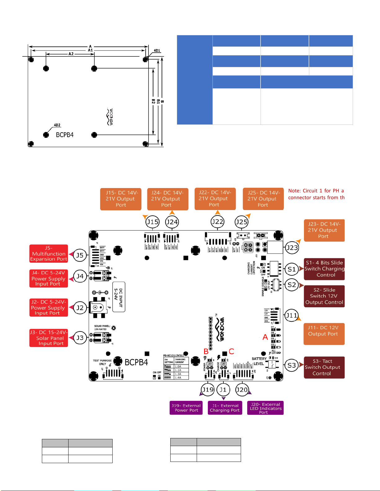
Note: All the components in the block diagram are grounded except Charging LED for External Port
(J1) and LED Display for External Port (J20). Lithium-Ion Cells are connected to battery protection
and balance circuit and then grounded. All the Power Output, including the battery level indication
module will be disconnected once the board goes into a protection mode. When the battery is fully
charged, the voltage across the charging LED shunt resistor is approximately 28V and drops
drastically to 0V when there is no power supplied to the board.
Applications:
· Industrial Applications
· DIY and IoT Purposes
· Power Bank for Router/
Drone/
· High Power Portable
Speaker
· Time Lapse Camera
Key Features:
·5-24V Wide Range Charging Voltage
·Large Battery Capacity with 5S
26650 Cells
·Battery Voltage Balancing
·Solar Charging Supported
·Multiple Output Ports
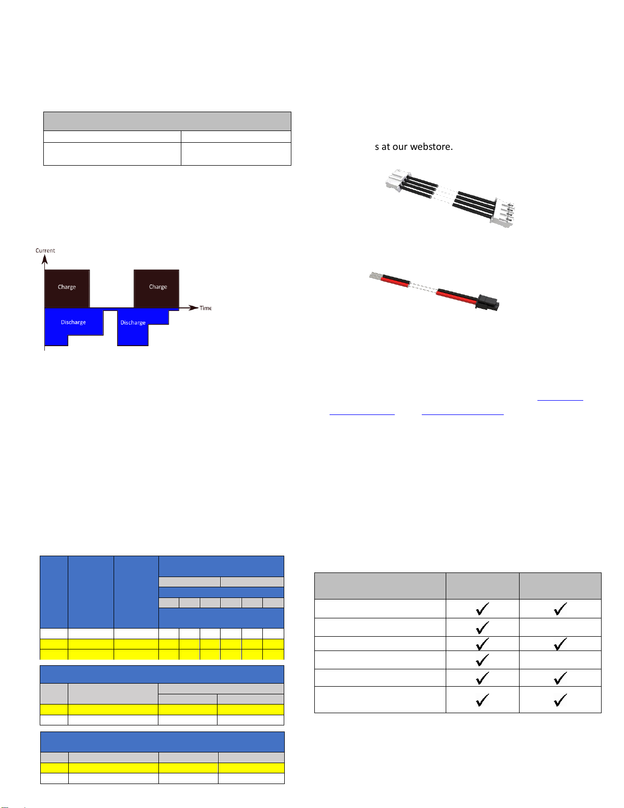
·Charge and Discharge at the Same
Time
Notes:
1. Sure Electronics does not provide technical support for any behavior of connecting the board with power supply
out of the recommended range. Any damage/problem arises due to this, will not be covered by the warranty.
2. Remove battery from the circuit board if it is not use for a long time.
3. For initial charging, it is normal for the board to take longer time to fully charge.
4. If the board goes into a protection mode or the battery has been re-installed, please recharge the board with DC
Input Jack to reactivate.
5. Please check the battery polarity before installation. This board can be used with Lithium-Ion battery ONLY. Other
batteries, including LiFePO4 is prohibited.
6. Please note, this board is prohibited to be connected in parallel or in series.
Ready for:
BCPB4 is a highly reliable Lithium-Ion Battery Charging, Protection, and Balancing Board that operates with wide input range, 5-24V.
This board able to charge the batteries from input voltages above, below, or equal to the output voltages. It is designed for 5 in series
26650 Lithium-Ion Battery which provides approximately 90-125Wh energy. The MPPT charging integrated feature supports a 15-24V
power supply. BCPB4 is complemented with a visualized display of battery level indicators. To ensure the reliability of this board, it is
equipped with full protection circuit; overcurrent, over-temperature, short circuit, and over/under voltage protection. The battery
balancing IC allows constant battery voltage between 5 in series 26650 Lithium-Ion cells. It is designed for industrial application with
verified MTBF for low-temperature increment under rigorous design.
·LED Indicators for Battery
Level
·Full Protection Circuit;
Short Circuit, Over-
temperature, Over/Under
Voltage, Over-current, Over-
charge and Over-discharge
Protection

Parameters
Conditions
Min.
Typ.
Max.
Unit
s
℃
3.2
3.4
3.6
3.8
4
4.2
0 200000 400000 600000 800000 1000000 1200000
Battery Voltage, V (Charging with
1.5A, 25℃)
Time,s
Battery Voltage, V (Charging with 0.8A, 25℃) vs Time
BAT1 BAT2
BAT3 BAT4
BAT5
3
3.2
3.4
3.6
3.8
4
4.2
0 200 400 600 800 1000
Battery Voltage, V (Discharging with
6A, 25℃)
Time,s
Battery Voltage, V (Discharging with 6A, 25℃) vs Time
BAT4
BAT2
BAT3
BAT1
BAT5
2
`
0
0.2
0.4
0.6
0.8
1
0 50000 100000 150000 200000 250000
0.5A Charge (Input) Current , A
Time, s
0.8A Charge (Input) Current vs Time
24V 19V 15V 12V 9V
Note: The battery balancing circuit in this board allows the charge and discharge voltage across 5S 26650 Lithium-Ion Battery to be almost the same. Balancing
is activated at the end of each charging cycle. OEM customers can require our raw test data of up to 200 charge/discharge test cycles to evaluate the battery
performance and the balancing performance. Test curves are based on batteries used up for less than 200 charge/discharge cycles. Batteries used for more
than 200 charge/discharge cycles will not absolutely be balanced during charging and discharging. Plus, the battery capacity might be less than the initial cycle.
Electrical Specifications
Specifications typical @ +25℃ unless otherwise noted. Specifications subject to change without notice.
Charge and Discharge Curve
Charge Characterization
Charge and Discharge Efficiency
Note: All parameters were tested with the GwInstek GDM-8341 multimeter. All charge and discharge curves are from Hioki LR8500 Data Loggers. For authorized
distributors and OEM customers who need more detailed performance graphs and parameter settings, please send an inquiry e-mail to us. Raw test data and
graphs from data analysis software will also be provided (Not available for retail customers).
0
0.5
1
1.5
2
0 50000 100000 150000 200000 250000 300000
0.5A Charge (Input) Current , A
Time, s
1.4 A Charge (Input) Current vs Time
24V 19V 15V 12V 9V

Cable Selections
AWG
Conductor
Cross
Section
(mm2)
Suggested
Metric
(mm2)
Number of 4-Pair Cables in Bundle
1
2-7
Temperature Rating (℃)
60
75
90
60
75
90
Maximum Current (A) per
Conductor
26
0.129
0.14
1
1
1
1
1
1
24
0.205
0.25
2
2
2
1
1.4
1.6
22
0.326
0.34
3
3
3
1.4
1.8
2.1
Note:
All the *item(s) will be provided upon requests through email.
Other items can be freely accessed and downloaded through our
webstore or YouTube.
Use 24 AWG or 0.25 mm2 only for JST-PH connectors while 22
AWG or 0.34 mm2 only for JST-XH output connector. The cable’s
temperature might be a little bit high. Take reference from the
table below to see the maximum current of JST-PH and JST-XH
connectors can withstand at different temperature. It is suggested
to use 18 AWG or 0.75mm2 at Molex Micro-Fit and Molex Mini-Fit
connectors while 20 AWG or 0.50mm2 for Wago 2060 connector
when connecting the board to the input ports. See Current
Derating Reference Information Table and Current Rating Table for
Micro-Fit and Mini-Fit respectively for future reference.
5.5/2.1mm or compatible plug is suggested for wide range DC Jack
input. For industrial customers, we provide customized wire
harness and 3D/2D wire diagram for your reference.
3
SELF DISCHARGE RATE
Battery
5% -10% / MONTH
Battery Protection Circuit
Standby Current Consumption
Typical 30 µA,
Maximum 45 µA
The self-discharge rate can be observed through the battery
discharging rate. The battery discharge rate is independent of the
circuit board discharging rate. Take reference from the battery
datasheet for battery charging rate’s details.
Standard Accessories
A dual header of PH 4-PIN cable and Micro-Fit 2-PIN cable
will be provided as standard accessories. You can cut the PH
4-PIN cable into half as shown in the picture below to get 2 PH
cables. LED battery display kit and L-bracket are optional
accessories for BCPB4. You can use your own cable for
other connectors or get the unprovided cable and optional
accessories at our webstore.
DC-Uninterrupted Power Supply
(UPS) Features
BCPB4 is designed as DC-Uninterrupted Power Supply (UPS). This
unique feature allows this board to be charged and discharged at
the same time, without interrupting.
For bulk purchases of more than 500 pieces, customers can
email to request for special quotation at info@sure-
Videos, Thermal Images, and STP Files are provided upon
requests (Applicable only for system integrator with bulk
purchase). STL Files, DWG Files, Product Videos, High
Resolutions Product Pictures are open for download to retail
customers. We will provide CE and FCC certificates upon
request for the customized bulk purchase. Our product is EU
REACH and RoHS 3 (EU 2015/863) compliant. Other necessary
files (not included in the BCPB4 product module) shall be
provided upon request from the system integrator, and bulk
purchasers.
Bulk Order Information
Item Provided
Bulk
Purchases
Retail Purchases
STL Files
STP Files*
DWG Files
4K Resolutions Videos*
Product Videos (YouTube)
High Resolutions Product
Pictures
Current Derating Reference Information for Molex Micro-Fit
AWG
Suggested Metric (mm2)
2-CKT
Wire to Wire
Wire to Board
18
0.75
7
8.5
20
0.5
6.5
7
Self Discharge Rate
Current Rating Wire to Wire and Wire to Board for Molex Mini-Fit
Connector
AWG
Suggested Metric (mm2)
2-3 -CKT
4-6 -CKT
18
0.75
9
8
20
0.5
7
6
Note: Current de-rating’s values are provided as guidelines, applicable
for not exceeding 30℃ temperatures rise ONLY.
a) JST-PH-4PIN
b) Micro-Fit-2PIN

4
Dimensions
Dimensions
A
(inch/mm)
A1
(inch/mm)
A2
(inch/mm)
6.0/ 152.45.7
5.60/ 142.2
2.40/ 61.0
B
(inch/mm)
B1
(inch/mm)
B2
(inch/mm)
D1
(mm)
D2
(mm)
3.6
*Use 3 mm or
#6-32 screw ONLY
(not provided)
3.6
*Use 3 mm or #6-32 screw ONLY
(not provided). Compatible with
BCPB2 or 3.6”x2.7” board from Sure
Electronic products.
Notes:
·All dimensions are typical in inches/mm
·Tolerance x.xx = ±0.004’’(±0.1mm)
·Battery holder’s height: 0.85’’/21.5 mm
·Board’s height: 0.10’’ /2.5 mm
·Maximum height of component’s side: 0.43’’/ 11.0 mm
·Total height: 1.38’’/ 35.0 mm
Pin Definitions
Input Options:
·J2 DC Wide Input Range 5-24V, 5.5/2.1mm Jack
·J4 DC Wide Input Range 5-24V Wago 2060
Circuit
Definition
1
VIN
2
GND
·J3 DC 15-24V Solar Panel Input Wago 2060
Circuit
Definition
1
VIN
2
GND
Note: Circuit 1 for PH and XH
connector starts from the left.
side.

LED Indicators (Position B) for Charge:
Mode
Status
Charging
Fully Charged
: ON : OFF
LED Indicators (Position C) for Power status:
Mode
Status
Power
No Power
: ON : OFF
5
Output Options:
·J22 DC 14V-21V JST XH-2.5mm 6-CKT
Circuit
Definition
1
BATT
2
BATT
3
BATT
4
GND
5
GND
6
GND
·J15, J24 DC 14V-21V JST PH-2mm 4-CKT
Circuit
Definition
1
BATT
2
BATT
3
GND
4
GND
·J25 DC 14V-21V Molex Micro-Fit 2-CKT
Circuit
Definition
1
BATT
2
GND
LED Indicators (Position A) for Battery Level Status:
·Four LED indicators for battery level status. Short press tact switch,
S3 to check battery level
External LED Indicators Port:
·J20 PH-2mm-6CKT
Circuit
Definition
1
POWER
2
SWITCH
3
LED4
4
LED3
5
LED2
6
LED1
LED Indicator for External Charging Port:
·J1 PH-2mm-2CKT
Circuit
Definition
1
LED+
2
LED-
LED Indicator for External Power Port:
·J19 PH-2mm-2CKT
Circuit
Definition
1
LED+
2
LED-
Charging Control: S1, 4 Bits Slide Switch
•S1 is used to set the 4 rated charge current. The current setting might
vary 10% for absolute value and another 20% for incremental.
•Use a smaller charge current to protect your battery. It is
recommended to use 1A for suggested 5000mAh battery kits for 5
hours minimum charge time.
•A higher charge current results in raising the battery’s internal
temperature because ions have finite mobility and are easily damaged
when charging with a high current.
•Hence, it is encouraged to charge your board at a low charging current
to prolong your battery life.
Number of Switch
Charge Current
0
0.8A
1
1.0A
2
1.1A
3
1.3A
4
1.4A
Output 5V Control:
·S2- 5V Slide Switch
Status
Function
ENABLE
Enable Discharging
DISABLE
Disable Discharging
Multifunction Expansion Port:
Only circuit 1 and 2 are designed for power input.
See BCPB-CB and BCPB-UC User Manuals
for detail explanation of this port.
·J5 PH-2mm-6-CKT
Circuit
Definition
1
VIN
2
VIN
3
GND
4
GND
5
BATT
6
BATT
·J23 DC 14V-21V Molex Mini-Fit 4-CKT
Circuit
Definition
1
BATT
2
BATT
3
GND
4
GND
·J11 DC 12V JST PH-2mm 4-CKT
This port is designed to supply +12V to the
port, board or any application that needs 12V;
Eg: BCPB2 and BCPB5.
Circuit
Definition
1
BATT
2
BATT
3
GND
4
GND
Table of contents