2
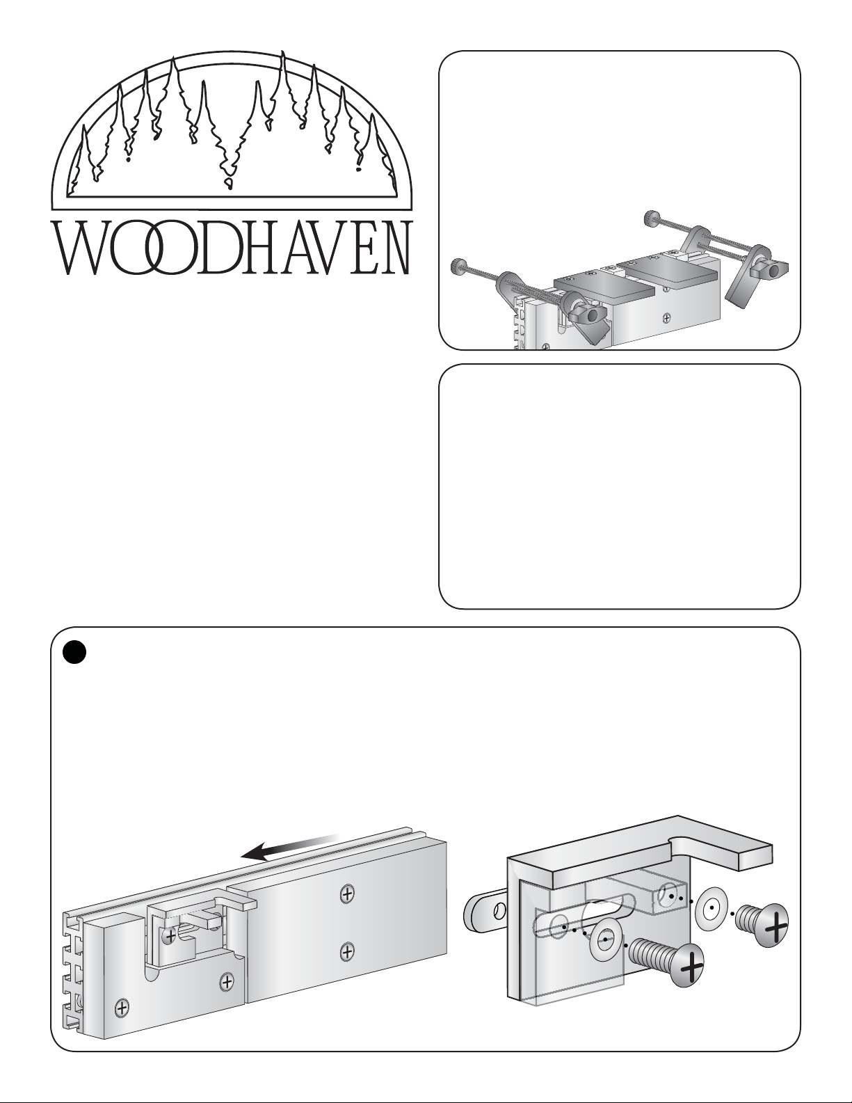
Adjust Aluminum
Stops for joint size:
Slide the right outside edge of the leg of the
Stationary Stop against the left outside edge of
the Setup Jig and tighten the Stationary Stop.
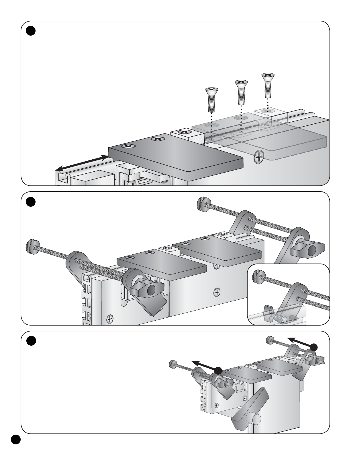
Rotate the Setup Jig 180º so the notch is against the
underside of the Router Supports and straddles both of the
legs of the Aluminum Stops. With the right inside edge of
the Setup Jig against the right outside edge of the leg of
the Stationary Stop, position the left edge of the leg of the
Adjustable Stop against the left inside edge of the Setup
Jig. Tighten the Adjustable Stop and remove the Setup Jig.
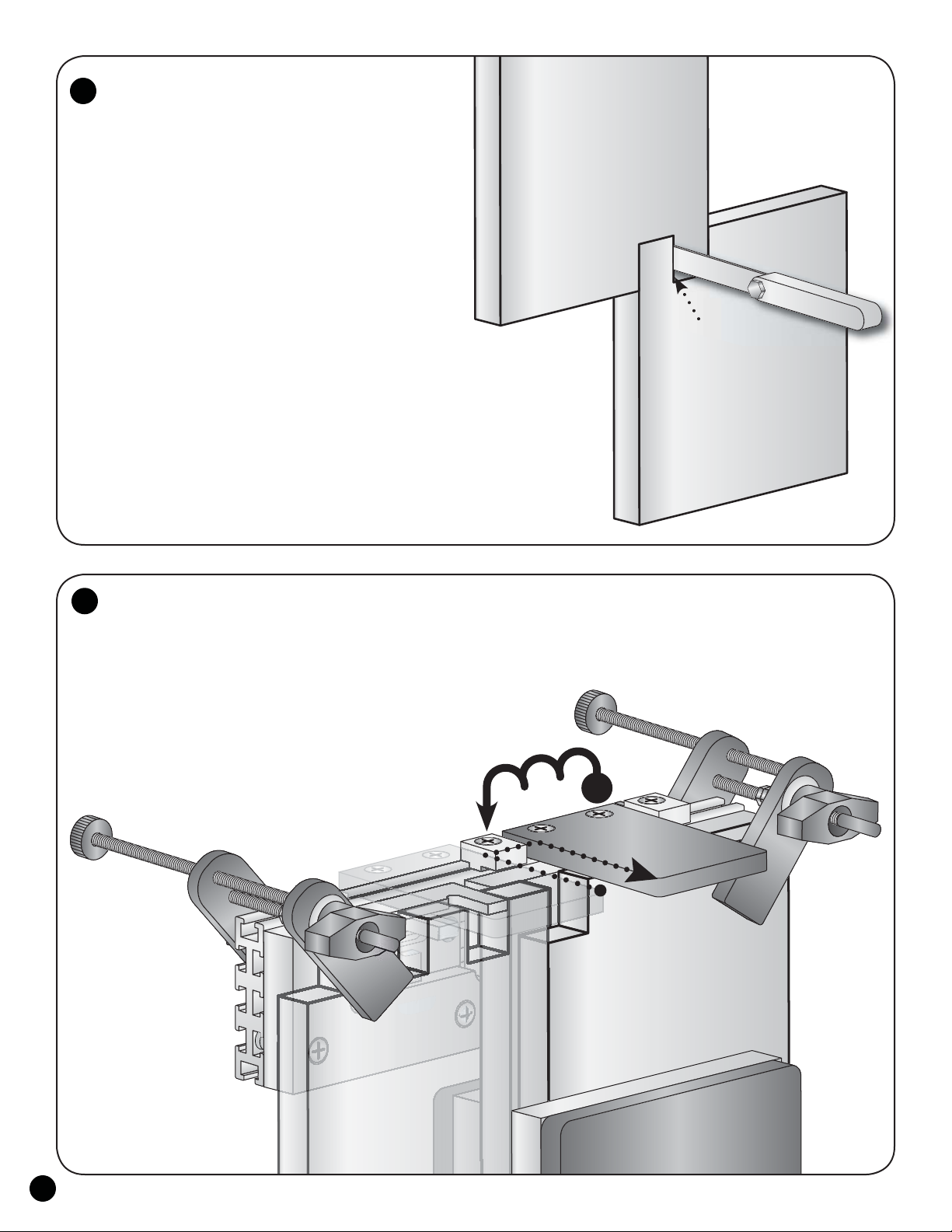
Test Cuts:
Use two wood scraps about 6" square. Clamp the bottom 2"
of one in a vise and rest the Left and Right Supports on the top
of the work, with the right side of the Stationary Aluminum Stop butted
against the left edge of the work. Adjust and tighten the right Clamp Pad
to hold the jig to the work. In addition, for the first and last few cuts of
every part, you'll need to use a small bar clamp to clamp the work to the
jig, since you can only use one of the two Clamp Pads for these cuts.
Set the cutting depth of the bit to the thickness of work
PLUS the thickness of the Left/Right Support PLUS the desired
amount of overhang. Any overhang can be removed later after
assembly by sanding or flush trimming. Make sure you allow for
this overhang when figuring the overall length of the work.
The Aluminum Stops protrude past the face of the Sub-Fence
and should always be to the left of the cutting path of the bit, when
viewed from the front. Before cutting, verify the bit will not contact
the Stops, Sub-Fence screws
or anything metallic.
Make the cut in a clockwise
fashion by running the bushing/
bit along the Left Router Support
until it bottoms out against the Router Stop(s),
move to the right, then come back out along
the Right Router Support. Wide or deep joints
require one of two cutting methods for best results:
A.) Cut at full depth, gradually roughing out most
of the center area first before making a light finish
cut along the Router Supports. B.) Make shallow
depths of cut until the full depth of cut is achieved.
Make sure the router is resting firmly on the
Left and Right Router Supports and that the bit is not
touching the work. Cut a single finger/notch in both test pieces.
6
7
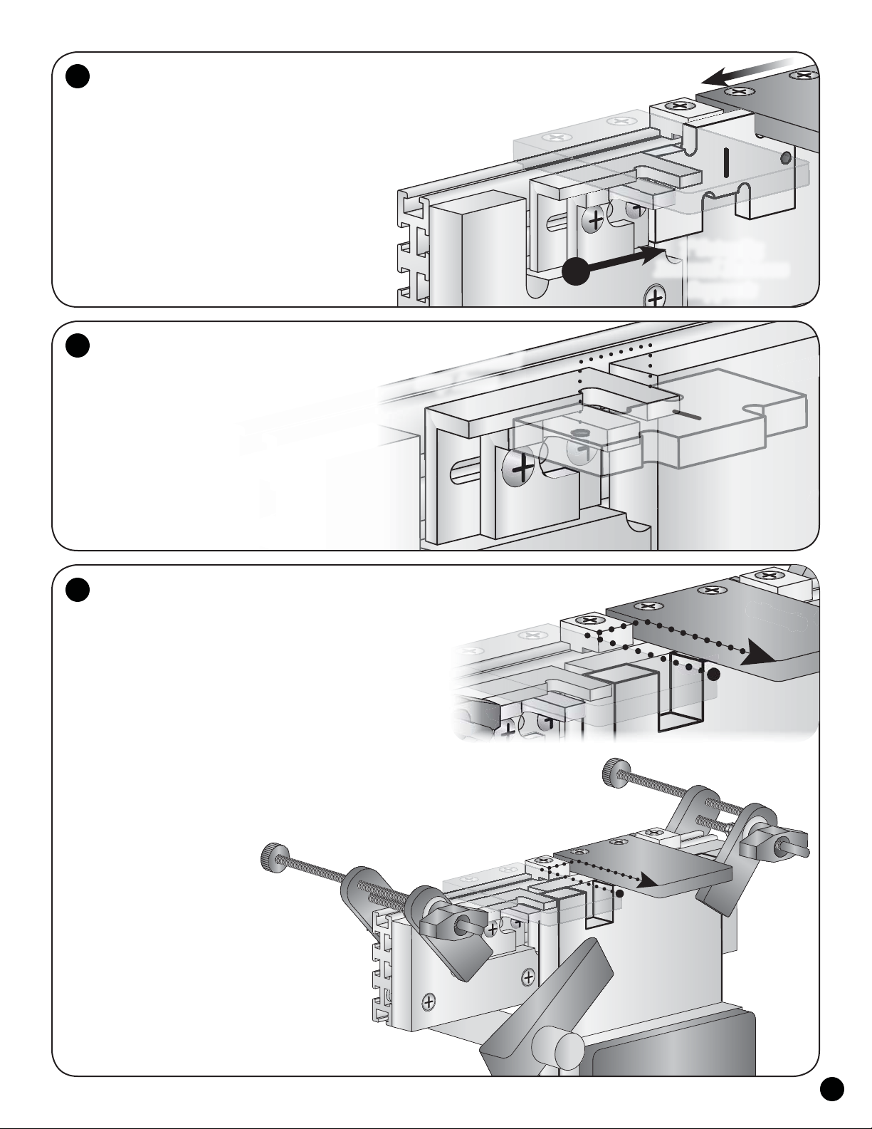
Adjust Right Router
Support for joint size:
The Right Router Support is the ONLY Support you'll
make any adjustments to during use. The Left Router Support
will always remain stationary. Adjusting the Right Support
in relation to the Left Support determines the width of cut.
From the Inch Setup Jigs, select the size joint (1/2", 3/4",
1", 1-1/4" & 1-1/2") you wish to cut and remove it from the
chain. Loosen the Right Support. Loosen both Aluminum
Stops and slide them to the far left. Sandwich the "tall"
portion of the selected Setup Jig between the Supports then
tighten the Right Support. When using the 1/2" Setup Jig,
check to make sure the 3/4" guide bushing will fit between the
Supports and readjust the Right Router Support as necessary.
5
1" Setup Jig
Indexed Between
Supports
1" Setup Jig
Indexed Around
Stop Arms
Stationary
Support
Router
Travel Path
Vise
Bar
Clamp
First
Edge
Second
Edge
Workpiece
One