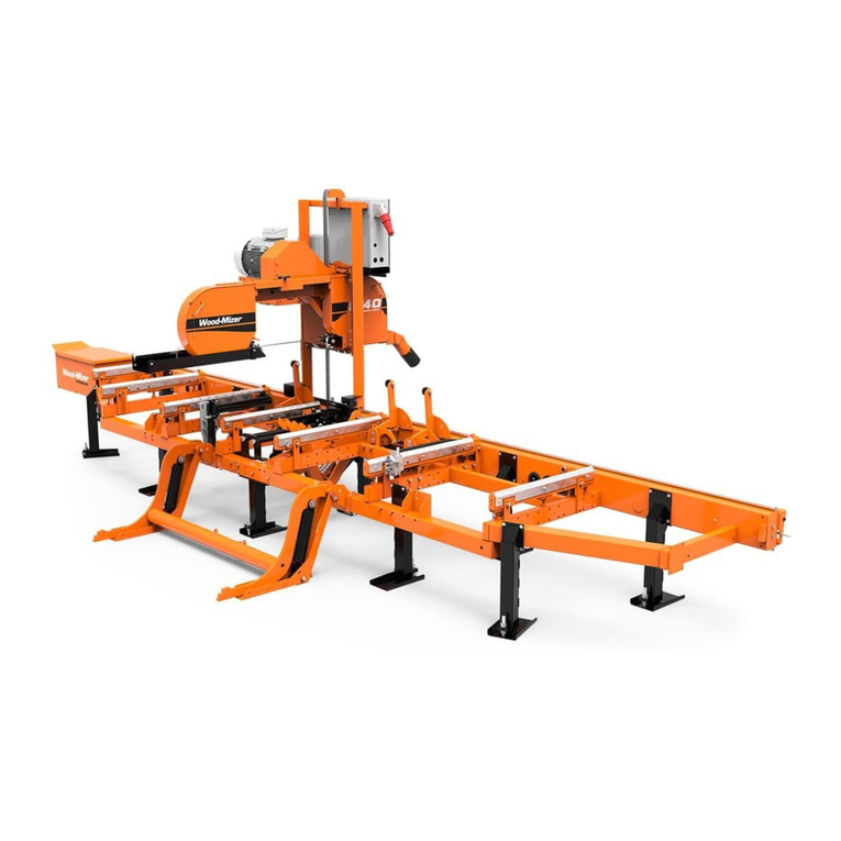
woodmizer LT70 Series Guide

G57 Engine
Safety, Operation,
Maintenance & Parts Manual
LT70 Series rev. F1.00
Safety is our #1 concern! Read and understand
all safety information and instructions before oper-
ating, setting up or maintaining this machine.
Form #2442
!

2 D42doc072321 Table of Contents
Table of Contents Section-Page
SECTION 1 OPERATION 1-1
1.1 Starting the Engine .................................................................................1-1
1.2 HMI Display...........................................................................................1-5
1.3 Engine Specifications ...........................................................................1-11
SECTION 2 MAINTENANCE 2-1
2.1 Safety......................................................................................................2-1
2.2 Engine Oil & Filter.................................................................................2-2
2.3 Cooling System ......................................................................................2-2
2.4 Air Cleaner .............................................................................................2-2
2.5 Fuel Filter ...............................................................................................2-3
2.6 Battery ....................................................................................................2-3
2.7 Alternator Belt........................................................................................2-4
2.8 Miscellaneous Maintenance ...................................................................2-5
SECTION 3 REPLACEMENT PARTS 3-1
3.1 How To Use The Parts List ....................................................................3-1
3.2 Sample Assembly ...................................................................................3-1
3.3 G57 Engine Kit.......................................................................................3-2
3.4 G57 Engine Assembly .........................................................................3-4
3.5 Engine Bracket Set .................................................................................3-7
3.6 G57 Engine Alternator Assembly ..........................................................3-9
3.7 Exhaust System w/Mount.....................................................................3-11
3.8 Acceleration & Braking Mechanism....................................................3-13
3.9 Fuel System ..........................................................................................3-15
3.10 Battery Box...........................................................................................3-16
3.11 Engine Guards .....................................................................................3-18
3.12 Fuel Tank Assembly, LT70 - G57 .......................................................3-21
3.13 Control Box, LT70-G57 (Accuset 2) ..................................................3-23
About This Manual doc072321 iii
ABOUT THIS MANUAL
This manual is provided as a supplement to the equipment manufacturer’s manual. This
manual provides information specific to the use of this equipment on the Wood-Mizer®
sawmill. Refer to the sawmill operator’s manual and manufacturer's manual before
attempting to operate this equipment.
IMPORTANT! Read the sawmill operator’s manual and
engine manufacturer’s manual for instructions and safety
precautions before operating this equipment.
The information and instructions given in this manual do not amend or extend the limited
warranties for the equipment given at the time of purchase.
ENGINE COMPONENTS
!
Air Filter
Muffler with
Cover, Catalyst
Converter and
Oxygen Sensors
Oil Drain Pipe
Fuel Supply Assem-
bly with Pump, Tank
and Filter
Radiator with Fan
and Reservoir
Centrifugal Clutch

Operation
Starting the Engine
1
1-1 G28doc072321 Operation
SECTION 1 OPERATION
1.1 Starting the Engine
Engine Control Lights
See Figure 1-1. The following indicator lights are located on the sawmill control panel.
Battery Charge Indicator: It lights up if the alternator is not charging the battery
EFI Diagnostic Indicator: A diagnostic light is provided to help troubleshoot the electronic
fuel injection system. See Engine error screen for details.
Blade Lube Indicator: It lights up/blinks if the blade lube is on.
FIG. 1-1

Operation
Starting the Engine
Operation G28doc072321 1-2
1
Control Panel
Refer to the sawmill Operator’s Manual.
Key switch (A):
Position 0 - engine ignition OFF, all electrical circuits are OFF.
Position 1 - engine ignition ON, all electrical circuits are ON.
Position 2 - engine starter is ON
Position 3 - engine ignition OFF, all electrical circuits are ON.
Blade drive switch (B):
Position 0 - Blade drive is OFF. Blade brake is ON.
Position 1 - Blade drive is ON. Blade brake is OFF.
To spin the blade wheels by hand (to track the blade), set the key switch to position 3 and
move the blade drive switch to position 1. IMPORTANT! After the blade tracking is done,
close the blade covers and move the blade drive switch back to position 0.
HMI Display (C): See Section 1.2HMI Display
FIG. 1-2
A
B
C
D

Operation
Starting the Engine
1
1-3 G28doc072321 Operation
Emergency stop button (D).
CAUTION! If at any time you need to immediately stop the
machine, press the emergency stop button. To re-start the
machine twist and release the emergency stop button first.
IMPORTANT! Wait 7 seconds before re-starting the
machine.
Engine Start
DANGER! Always be sure the blade is disengaged and all
persons are out of the path of the blade before starting the
engine Failure to do so will result in serious injury.
DANGER! Operate your engine/machine only in well-venti-
lated areas. The exhaust gases of your engine can cause
nausea, delirium and potentially death unless adequate
ventilation is provided.
DANGER! Never operate an engine with a fuel or oil leak.
The leaking fuel or oil could potentially come in contact with
hot surfaces and ignite into flames.
WARNING! Be sure the power feed switch is in the neutral
position before turning the key switch to the “1”, “2” or “3”
position. This prevents accidental carriage movement
which may cause serious injury or death.
WARNING! Do not operate engine without proper and
operational spark arrester/muffler. Sparks emitted from the
engine exhaust could ignite surrounding materials, causing
serious injury or death.
IMPORTANT! Let the engine run idle for 3 minutes to warm
up before applying load.
Open the fuel valve located on the fuel tank.
Be sure the blade drive switch is in position 0.
Turn the key switch to position 1. Check if the EFI indicator light is ON.
Turn the key switch to position 2 and release.
!
!

Operation
Starting the Engine
Operation G28doc072321 1-4
1
Check if the battery charge indicator, the oil pressure indicator (located on the HMI
display) and the EFI indicator are OFF. If not, stop the engine immediately.
For more information, see the engine manufacturer’s operation manual.
Engine Shut-off
Set the blade drive switch to position 0.
Let the engine run idle for 2 minutes to cool it down.
Turn the key switch to position 0.

Operation
HMI Display
1
1-5 G28doc072321 Operation
1.2 HMI Display
Start-up
After switching the key switch to position 1 (or 3), the initial welcome “Wood-Mizer” screen
will appear.
The HMI contains four main screens available for the sawmill operator’s:
FIG. 1-3
Screen #1 Screen #2
Screen #4 Screen #3

Operation
HMI Display
Operation G28doc072321 1-6
1
Screen #1
1. Current engine load.
2. Current engine RPM.
3. Current engine coolant temperature.
4. Debarker icon (ON when debarker is working).
5. Oil pressure icon (ON when the oil pressure is too low). The icon should be ON when the
engine ignition is ON and should go out immediately after the engine started.
6. Voltage of the sawmill electric circuit. When the engine is running it should indicate
14,2-14,6V. When the engine is OFF - above 12V. If the value is lower than 12V, the bat-
tery needs to be charged.
7. Temporary fuel consumption (in liters per hour).
8. Debarker status: 1-ON / 0-OFF.
9. Auto clutch status: 1 - Blade drive is engaged / 0 - Blade drive is disengaged.
10. Requested blade linear speed. Can be changed from 21m/s to 37m/s.
FIG. 1-4
23
145
6
7
8
9
10
11 13
13
12

Operation
HMI Display
1
1-7 G28doc072321 Operation
11. Buttons used to increase and decrease the blade speed.
12. Press to save requested blade speed.
13. Press to switch between HMI screens.
Screen #2
1. Current engine load.
2. Current engine RPM.
3. Current engine coolant temperature.
4. Debarker icon (ON when debarker is working).
5. Oil pressure icon (ON when the oil pressure is too low). The icon should be ON when the
engine ignition is ON and should go out immediately after the engine started.
6. Voltage of the sawmill electric circuit.
7. Temporary fuel consumption (in liters per hour).
8. Press to enter the “Setting language” screen. See Section Language settings screen.
FIG. 1-5
23
145
6
7
811
11 910

Operation
HMI Display
Operation G28doc072321 1-8
1
9. Press to switch between the day and night modes.
10. Press to switch between “Engine hours” and “Fuel rate” screens.
11. Press to switch between HMI screens.
Screen #3
1. Oil pressure. If the oil pressure indicator is on, the oil pressure is too low.
2. Voltage of the sawmill electric circuit. When the engine is running it should indicate
14,2-14,6V. When the engine is OFF - above 12V. If the value is lower than 12V, the bat-
tery needs to be charged.
3. Temporary Fuel Consumption.
4. Throttle Position.
5. Actual Engine RPM.
6. Requested blade linear speed.
7. Intake Manifold Air Temperature.
8. Engine Coolant Temperature. The normal working temperature for the engine is 50-90oC.
9. Auto clutch status: 1 - Blade drive is engaged / 0 - Blade drive is disengaged.
FIG. 1-6
2
3
1
4
5
6
7
8
9
10
11
12
13 14 15

Operation
HMI Display
1
1-9 G28doc072321 Operation
10. Debarker status 1-ON / 0-OFF.
11. Intake Manifold Air Pressure.
12. Engine working hours.
13. Press to switch between the day and night modes.
14. Press to enter engine error screen See Section Engine error screen.
15. Press to enter diagnostic screen - for service purposes only. Access is password pro-
tected.
Screen #4
1. Switching between day and night brightness settings. Use “-” and “+” buttons to change
the percentage value of brightness.
2. This button saves the selected brightness value.
3. Back to the #3 screen.
FIG. 1-7
1
2
3

Operation
HMI Display
Operation G28doc072321 1-10
1
Language settings screen.
Use “-” and “+” buttons to set the language.
1. Back to the screen #2
2. Saves the selected language.
Engine error screen
1. Back to the screen #3
2. Toggle the errors stored in the controller memory.
Enter this screen if the EFI Diagnostic Indicator light is on. Note down the SPN and FMI
codes and pass this information to the Wood-Mizer Customer Service. When the EFI
FIG. 1-8
FIG. 1-9
1
2
1
2

Operation
Engine Specifications
1
1-11 G28doc072321 Operation
Diagnostic Indicator light is on, engine RPM is limited to 2500 to avoid engine damage.
1.3 Engine Specifications
G57 Kubota
Type
Liquid cooled, 4-cycle, gasoline,
OHV, electronic fuel injection
Number of cylinders 4
Bore and stroke mm 79 x 78,4
Total displacement cm31537
Power H.P. ( SAEJ 1995 ) [HP/min-1 ( rpm )] 57/3600
Max Torque [Nm /min-1 ( rpm )] 120/2400
Dry Weight kg [ lbs. ] 119 [262]
Fuel Unleaded gasoline
CO2 Emission data g/kWh 1090
Oil Capacity (w/filter) l. 6L

Maintenance
Safety
Maintenance G28doc072321 2-1
2
SECTION 2 MAINTENANCE
Refer to the manufacturer’s manual for maintenance intervals and procedures unless
otherwise instructed in this manual. Follow the manufacturer’s recommendations for
dusty conditions.
IMPORTANT! This manual only provides information about
additional procedures or procedures to be performed at
different time intervals than found in the manufacturer's
manuals. Refer to the manufacturer's manual for complete
maintenance instructions.
2.1 Safety
Use caution when performing maintenance or service to the engine.
DANGER! Always be aware of and take proper protective
measures against rotating shafts, pulleys, fans, etc. Always
stay a safe distance from rotating members and make sure
that loose clothing or long hair does not engage rotating
members resulting in possible injury.
DANGER! Engine components can become very hot during
operation. Avoid contact with any part of a hot engine. The
exhaust components of your engine are especially hot
during and following operation. Contact with hot engine
components can cause serious burns. Therefore, never
touch or perform service functions on a hot engine. Allow
the engine to cool sufficiently before beginning any service
function.
WARNING! Remove the blade before performing any
engine service. Failure to do so may result in serious injury.
WARNING! Always wear proper and necessary safety
equipment when performing service functions. Proper
safety equipment includes eye protection, breathing
protection, hand protection and foot protection.
This symbol identifies the interval (hours of operation) at which each maintenance
procedure should be performed. "AR" signifies maintenance procedures which should be
performed as required.
!
0

Maintenance
Engine Oil & Filter
2
2-2 G28doc072321 Maintenance
2.2 Engine Oil & Filter
Check the oil level every 8 hours of operation. Add oil as necessary. See the engine
manual for oil viscosity and grade recommendations.
IMPORTANT! During initial break-in, change the oil and the
oil filter after the first 50 hours and every 150-200 hours
thereafter. Continue to check oil level every 8 hours of
operation and refill as necessary.
NOTE: Engine in factory is filled with 10W/40 Shell Helix HX7, semi-synthetic oil.
2.3 Cooling System
Brush off sawdust and debris every 50 hours of operation. Clean the grass screen,
cooling fins, and external surfaces. Remove any dust, dirt or oil. See engine manual for
further instructions.
2.4 Air Cleaner
Empty the air debris collector every 8 hours of operation.
Open the air filter intake cover by loosing latches and remove all debris and dust. After all
debris has been emptied close the cover.
WARNING! Always wear proper and necessary safety
equipment when performing service functions. Proper
safety equipment includes eye protection, breathing protec-
tion, hand protection and foot protection.
Replace the outer air cleaner cartridge and check the inner cartridge every 250 hours of
operation or more often if operating the sawmill in dirty conditions or if engine perfor-
mance indicates a new cartridge is necessary.
CAUTION! Do not clean elements with water or com-
pressed air. Do not handle the inner element unless it is to
be changed. Handle new elements carefully. Contact with
the element could cause damage and prevent the filter from
operating properly.
Replace the inner air cleaner cartridge every 1200 hours of operation or more often if
operating the sawmill in dirty conditions.
8
!
150
50
8
250
1200

Maintenance
Fuel Filter
Maintenance G28doc072321 2-3
2
2.5 Fuel Filter
Replace the fuel filter every 100 hours of operation or as required for engine perfor-
mance.
2.6 Battery
Check the battery electrolyte level every 50 hours of operation. See manufacturer’s
manual for instructions.
DANGER! Batteries expel explosive gases. Keep sparks,
flames, burning cigarettes, or other ignition sources away at
all times. Always wear safety goggles and a face shield
when working near batteries. Failure to do so will cause
serious injury.1
WARNING! Battery posts, terminals and related
accessories contain lead and lead compounds, chemicals
known to the State of California to cause cancer and
reproductive harm. Wash hands after handling.
1. Battery Council International, copyright 1987
100
50

Maintenance
Alternator Belt
2
2-4 G28doc072321 Maintenance
2.7 Alternator Belt
Adjust the alternator belt as needed. Check the alternator belt for tension and wear when
battery is not charging properly or when the alternator belt is squeaking.
To Tighten The Belt:
3. Unscrew four bolts (A) and remove alternator belt cover.
See Figure 2-1.
FIG. 2-1
AR
A

Maintenance
Miscellaneous Maintenance
Maintenance G28doc072321 2-5
2
4. Loosen the mounting bolts (B) and locking bolt (C).
See Figure 2-2.
5. Using the adjustment bolt (D) set the alternator belt tension until the belt has 5 mm deflec-
tion with a 2.5 kg. deflection force. Re-tighten the locking nut.
6. Reinstall alternator belt cover.
2.8 Miscellaneous Maintenance
Clean and inspect the spark arresters every 50 hours of operation. Replace if damaged.
Inspect the spark plugs every 100 hours of operation. Remove any deposits and adjust
gap if necessary. See engine manual for further information.
CAUTION! Do not remove the plug wire to check for
electrical spark. Damage to the ignition circuit will result.
FIG. 2-2
B
C
D
50
100

REPLACEMENT PARTS
How To Use The Parts List
3
3-1 doc072321 REPLACEMENT PARTS
SECTION 3 REPLACEMENT PARTS
3.1 How To Use The Parts List
Use the index above to locate the assembly that contains the part you need.
Go to the appropriate section and locate the part in the illustration.
Use the number pointing to the part to locate the correct part number and descrip-
tion in the table.
Parts shown indented under another part are included with that part.
Parts marked with a diamond () are only available in the assembly listed above the
part.
See the sample table below. Sample Part #A01111 includes part F02222-2 and subas-
sembly A03333. Subassembly A03333 includes part S04444-4 and subassembly
K05555. The diamond () indicates that S04444-4 is not available except in subassembly
A03333. Subassembly K05555 includes parts M06666 and F07777-77. The diamond ()
indicates M06666 is not available except in subassembly K05555.
To Order Parts:
From Europe call our European Headquarters and Manufacturing Facility in Kolo,
Poland at +48-63-2626000. From the continental U.S., call our toll-free Parts hotline
at 1-800-525-8100. Have your customer number, vehicle identification number, and
part numbers ready when you call. From other international locations, contact the
Wood-Mizer distributor in your area for parts.
Office Hours:
CAUTION! It is strongly recommended that only original
spare parts be used.
3.2 Sample Assembly
REF. DESCRIPTION ( Indicates Parts Available In Assemblies Only) PART # QTY
SAMPLE ASSEMBLY, COMPLETE (INCLUDES ALL INDENTED PARTS BELOW) A01111 1
7Sample Part F02222-22 1
Sample Subassembly (Includes All Indented Parts Below) A03333 1
8Sample Part ( Indicates Part Is Only Available With A03333) S04444-4 1
Sample Subassembly (Includes All Indented Parts Below) K05555 1
9Sample Part ( Indicates Part Is Only Available With K05555) M06666 2
10 Sample Part F07777-77 1
Country Monday - Friday Saturday Sunday
POLAND 7-15 CLOSED CLOSED
US 8 A.M.- 5 P.M. 8 A.M. - 5 P. M. CLOSED
Other manuals for LT70 Series
6
Table of contents
Other woodmizer Engine manuals

woodmizer
woodmizer LT35 Guide

woodmizer
woodmizer G13 Guide

woodmizer
woodmizer D19 Guide

woodmizer
woodmizer D42 Guide

woodmizer
woodmizer D19 Guide

woodmizer
woodmizer LT28 D19 Guide

woodmizer
woodmizer D34 Guide

woodmizer
woodmizer LT28 G25 Guide

woodmizer
woodmizer LT40 MH Series Guide

woodmizer
woodmizer LT28 G25 Guide