woodmizer LT30 Super Guide

G35 Engine
Safety, Operation, Maintenance
& Parts Manual
LT30 Super rev. F7.00 - J2.00
LT40 Super rev. F8.00 - J3.00
LT30HD Super rev. G1.00 - J7.00
LT40HD Super rev. G1.00 - J7.00
Safety is our #1 concern! Read and understand
all safety information and instructions before oper-
ating, setting up or maintaining this machine.
February 1998 Form #767

ii G3597doc080906 Table of Contents
Table of Contents Section-Page
ABOUT THIS MANUAL IV
SECTION 1 OPERATION 1-1
1.1 Starting The Engine................................................................................1-1
SECTION 2 MAINTENANCE 2-1
2.1 Safety......................................................................................................2-1
2.2 Air Cleaner .............................................................................................2-2
2.3 Fuel Filter ...............................................................................................2-3
2.4 Battery ....................................................................................................2-4
2.5 Alternator Belt........................................................................................2-5
2.6 RPM Adjustments ..................................................................................2-8
SECTION 3 REPLACEMENT PARTS 3-1
3.1 Fuel Tank................................................................................................3-1
3.2 Engine Mount Assembly........................................................................3-2
3.3 Engine Assembly....................................................................................3-4
3.4 Alternator Assembly...............................................................................3-6
LT30 Super Rev. G6.00+
LT40 Super Rev. G7.00+
LT30HD Super Rev. H1.00+
LT40HD Super Rev. H1.00+
3.5 Alternator Assembly...............................................................................3-8
LT30 Super Rev. F7.00 - G5.00
LT40 Super Rev. F8.00 - G6.00
LT30HD Super Rev. G1.00 - G9.00
LT40HD Super Rev. G1.00 - G9.00
3.6 Air Cleaner Assembly ..........................................................................3-10
3.7 Throttle/Choke Assembly.....................................................................3-11
LT30 Super Rev. G5.00+
LT40 Super Rev. G6.00+
LT30HD Super Rev. G9.00+
LT40HD Super Rev. G9.00+
3.8 Throttle/Choke Assembly.....................................................................3-13
LT30 Super Rev. F7.00 - G4.02
LT40 Super Rev. F8.00 - G5.02
LT30HD Super Rev. G1.00 - G8.02
LT40HD Super Rev. G1.00 - G8.02
3.9 Muffler Assembly.................................................................................3-15
3.10 Drive Assembly....................................................................................3-16
TOC

Table of Contents Section-Page
Table of Contents G3597doc080906 iii
3.11 Drive Assembly....................................................................................3-17
LT30 Super Rev. F7.00 - H3.00
LT40 Super Rev. F8.00 - H4.00
LT30HD Super Rev. G1.00 - H7.00
LT40HD Super Rev. G1.00 - H7.00
3.12 Engine Pulley Guards...........................................................................3-18
LT30 Super Rev. G6.00+
LT40 Super Rev. G7.00+
LT30HD Super Rev. H1.00+
LT40HD Super Rev. H1.00+
3.13 Engine Pulley Guards...........................................................................3-19
LT30 Super Rev. F7.00 - G5.00
LT40 Super Rev. F8.00 - G6.00
LT30HD Super Rev. G1.00 - G9.00
LT40HD Super Rev. G1.00 - G9.00
INDEX I

iv G3597doc080906 About This Manual
ABOUT THIS MANUAL
This manual is provided as a supplement to the equipment manufacturer’s manuals. This
manual provides information specific to the use of this equipment on the Wood-Mizer®
sawmill. Refer to the sawmill operator’s manual and manufacturer's manual before
attempting to operate this equipment.
IMPORTANT! Read the sawmill operator’s manual and
engine manufacturer’s manual for instructions and safety
precautions before operating this equipment.
The information and instructions given in this manual do not amend or extend the limited
warranties for the equipment given at the time of purchase.
ENGINE COMPONENTS
A
ir Cleaner
Mu
ff
ler
Serial Number/
Engine Type
3H0713-7
Alternato
r
Starter

Operation
Starting The Engine
Operation G3597doc080906 1-1
1
SECTION 1 OPERATION
1.1 Starting The Engine
Engine Control Lights
See Figure 1-1. The following indicator lights are located on the sawmill control panel.
Alternator Charge Indicator: Lights up if the alternator is not charging the battery.
Key Switch Indicator: Lights up when the key is in either the on or accessory (#1 or #3)
position.
FIG. 1-1

Operation
Starting The Engine
1
1-2 G3597doc080906 Operation
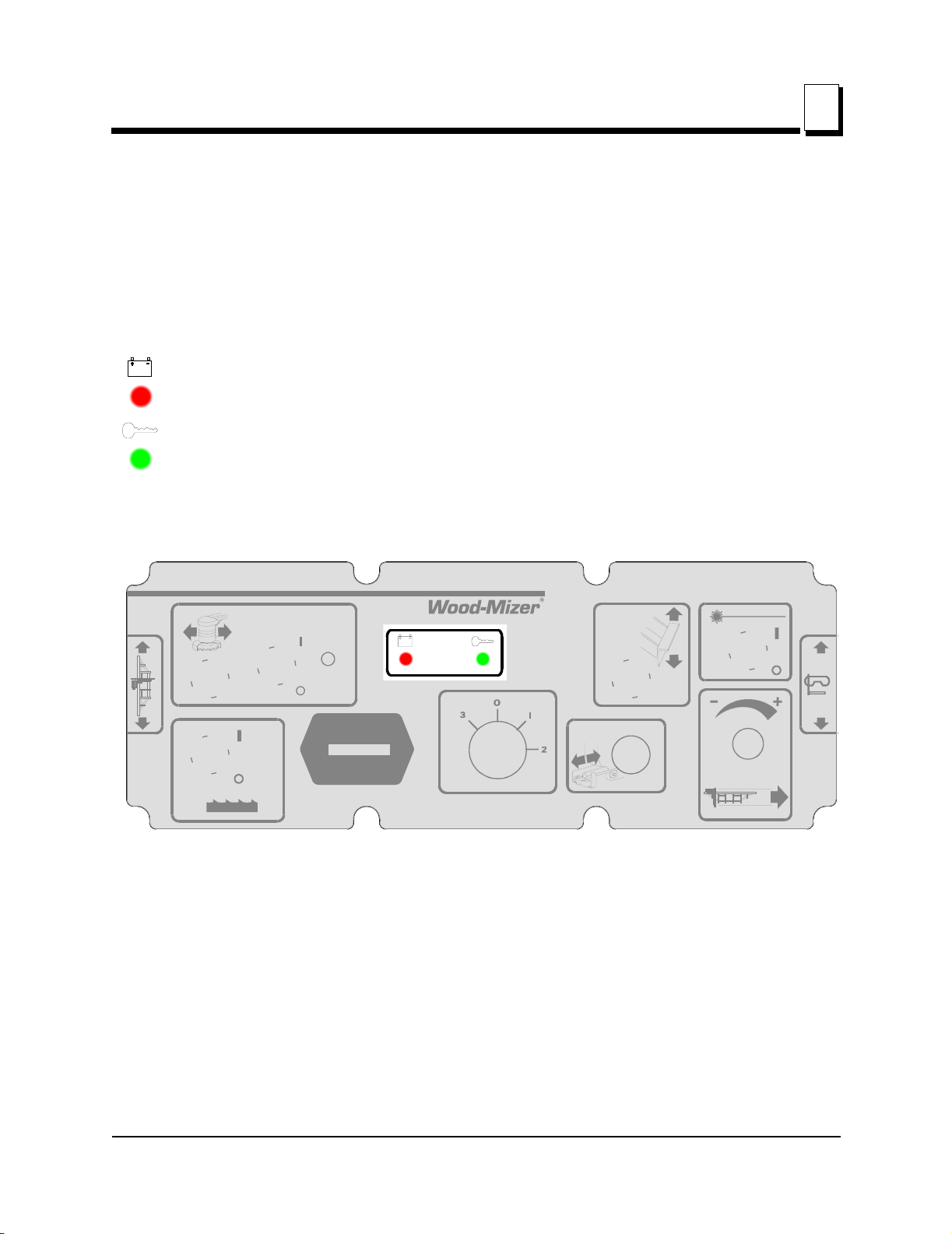
Engine Start
DANGER! Always be sure the blade is disengaged and all
persons are out of the path of the blade before starting the
engine. Failure to do so will result in serious injury.
DANGER! Operate your engine/machine only in well venti-
lated areas. The exhaust gases of your engine can cause
nausea, delirium and potentially death unless adequate
ventilation is present.
DANGER! Never operate an engine with a fuel or oil leak.
The leaking fuel or oil could potentially come in contact with
hot surfaces and ignite into flames.
WARNING! Be sure the power feed switch is in the neutral
position before turning the key switch to the on (#1) or
accessory (#3) position. This prevents accidental carriage
movement. which may cause serious injury or death.
WARNING! Do not operate engine without proper and
operational spark arrester/muffler. Sparks emitted from the
engine exhaust could ignite surrounding materials, causing
serious injury or death.
Turn the key switch to the start (#2) position and release.
If the engine needs choking to start, pull the choke cable out until the engine starts. Push
the choke wire in after the engine starts.
For more information, see the engine manufacturer’s operation manual.
LT30 Super rev. F7.00 - F8.01
LT40 Super rev. F8.00 - F9.01
LT30HD Super rev. G1.00 - G2.01
LT40HD Super rev. G1.00 - G2.01
If the fuel tank was recently filled or replaced, squeeze the primer bulb once or twice
before trying to start the engine. NOTE: If pumping problems are experienced, make sure
the out-flow end of the hose line is connected to the fuel filter. If pumping problems are
still experienced, hold the primer bulb in a vertical position while squeezing. This allows
the fuel check valve to operate properly.

Operation
Starting The Engine
Operation G3597doc080906 1-3
1
Engine Shutoff
CAUTION! A minimum 2 minute idle time is recommended
to allow the battery charge to recover before the engine is
shut off.
Turn the key switch to the off (#0) position.

Maintenance
Safety
2
2-1 G3597doc080906 Maintenance
SECTION 2 MAINTENANCE
Refer to the manufacturer’s manual for maintenance intervals and procedures unless oth-
erwise instructed in this manual. Follow the manufacturer’s recommendations for dusty
conditions.
IMPORTANT! This manual only provides information about
additional procedures or procedures to be performed at dif-
ferent time intervals than found in the manufacturer's manu-
als. Refer to the manufacturer's manual for complete
maintenance instructions.
2.1 Safety
Use caution when performing maintenance or service to the engine.
DANGER! Always be aware of and take proper protective
measures against rotating shafts, pulleys, fans, etc. Always
stay a safe distance from rotating members and make sure
that loose clothing or long hair does not engage rotating
members resulting in possible injury.
DANGER! Engine components can become very hot during
operation. Avoid contact with any part of a hot engine. The
exhaust components of your engine are especially hot dur-
ing and following operation. Contact with hot engine com-
ponents can cause serious burns. Therefore, never touch
or perform service functions on a hot engine. Allow the
engine to cool sufficiently before beginning any service
function.
WARNING! Remove the blade before performing any
engine service. Failure to do so may result in serious injury.
WARNING! Always wear proper and necessary safety
equipment when performing service functions. Proper
safety equipment includes eye protection, breathing protec-
tion, hand protection and foot protection.
This symbol identifies the interval (hours of operation) at which each maintenance pro-
cedure should be performed. "AR" signifies maintenance procedures which should be
performed as required.
0

Maintenance
Air Cleaner
Maintenance G3597doc080906 2-2
2
2.2 Air Cleaner
Replace the air cleaner cartridge every 200 hours of operation. Change the cartridge
more often if operating the sawmill in dirty conditions or if engine performance indicates a
new cartridge is necessary.
WARNING! Always wear proper and necessary safety
equipment when performing service functions. Proper
safety equipment includes eye protection, breathing protec-
tion, hand protection and foot protection.
200

Maintenance
Fuel Filter
2
2-3 G3597doc080906 Maintenance
2.3 Fuel Filter
Replace the fuel filter every 100 hours of operation or as required for engine perfor-
mance.
100

Maintenance
Battery
Maintenance G3597doc080906 2-4
2
2.4 Battery
Check the battery electrolyte level every 50 hours of operation. See manufacturer’s man-
ual for instructions.
DANGER! Batteries expel explosive gases. Keep sparks,
flames, burning cigarettes, or other ignition sources away at
all times. Always wear safety goggles and a face shield
when working near batteries. Failure to do so will cause
serious injury.1
WARNING! Battery posts, terminals and related accesso-
ries contain lead and lead compounds, chemicals known to
the State of California to cause cancer and reproductive
harm. Wash hands after handling.
1. Battery Council International, copyright 1987
50

Maintenance
Alternator Belt
2
2-5 G3597doc080906 Maintenance
2.5 Alternator Belt
LT30 Super Rev. G6.00+
LT40 Super Rev. G7.00+
LT30HD Super Rev. H1.00+
LT40HD Super Rev. H1.00+
The belt tension should be checked after the first 100 hours of operation, when the bat-
tery is not charging properly or when the alternator belt is squealing. If the battery contin-
ues to not charge properly or the belt continues to squeal after the initial belt adjustment,
replace the belt.
IMPORTANT! Sawmills built prior to March 1999 were pro-
vided with a sight hole in the alternator bracket to gauge
belt tension. To achieve proper belt tension, do not use the
sight hole. Follow the procedure below to check the belt
tension and adjust if necessary.
1. Release the blade tension and remove the blade from the sawmill if necessary. Turn the
key switch to OFF (0) and remove the key.
2. Remove the drive belt cover and alternator cover.
See Figure 2-1.
3. Use a belt tension gauge to measure the belt tension. Place the gauge on the belt at the
midpoint between the two pulleys. If the belt tension is less than 3/16” with 9 lb. of deflec-
FIG. 2-1
AR
Belt Adjustment
Bolt
Jam Nut Upper Pivot
Lower
Pivot
3H0748-11

Maintenance
Alternator Belt
Maintenance G3597doc080906 2-6
2
tion, tighten the belt as described below.
4. Loosen the upper pivot, lower pivot and the adjustment bolt jam nut.
5. Turn the belt tension adjustment bolt clockwise to tighten the belt, counterclockwise to
loosen the belt. Adjust the bolt until the proper belt tension is achieved.
CAUTION! Do not overtighten the alternator belt. Damage
to the alternator will occur.
6. After the alternator belt has been tensioned, tighten the adjustment bolt jam nut. Tighten
the upper and lower pivots and replace the belt covers.
LT30 Super Rev. F7.00 - G5.00
LT40 Super Rev. F8.00 - G6.00
LT30HD Super Rev. G1.00 - G9.00
LT40HD Super Rev. G1.00 - G9.00
Replace the alternator belt every 1000 hours.
Check the alternator belt tension every 500 hours. Also check the alternator belt for ten-
sion and wear when battery is not charging properly or when the alternator belt is squeal-
ing. Adjust as needed.
1. Remove the alternator belt guard.
2. Loosen the two bolts in the slotted alternator bracket holes (opposite holes in front and
rear of bracket.
1000
500

Maintenance
Alternator Belt
2
2-7 G3597doc080906 Maintenance
See Figure 2-2.
3. Pivot the alternator to tighten the belt. Retighten the adjustment bolts and replace the belt
guard.
FIG. 2-2
3H0391
Loosen
bolts (2)
Pivot alternator
to tighten belt

Maintenance
RPM Adjustments
Maintenance G3597doc080906 2-8
2
2.6 RPM Adjustments
WARNING! Remove the blade before performing any
engine service. Failure to do so may result in serious injury.
Check the RPM with a tachometer after the first 20 hours of operation and every 200
hours thereafter.
See Table 2-1.
Before checking the RPM, make sure belt and brake strap tensions are correct (See Saw-
mill Maintenance). Also check oil, fuel, and coolant levels.
Make sure the throttle cable does not affect the engine RPM when the clutch handle is
disengaged. Make sure the cable is not bent or kinked.
1. Use the bottom threaded cable mount to adjust the throttle cable. When the clutch handle
is disengaged, the throttle cable should be taut but the spring not extended. When the
clutch handle is engaged, the throttle spring should extend 1/8" to 1/4". Once the throttle
cable is adjusted properly, use the adjustments provided on the engine to adjust the
engine RPM (3200[+0, -100] high-end, 1500[±100] idle).
CAUTION! Do not extend the throttle spring over 1/4".
Excessive tension may cause the throttle cable to fail pre-
maturely.
Engine High End RPM Low End RPM
G35 3200 1500
TABLE 2-1
200

Maintenance
RPM Adjustments
2
2-9 G3597doc080906 Maintenance
See Figure 2-3.
2. The low-end RPM should be 1500. To adjust the low-end RPM, use the throttle stop
screw. Turn the screw in or out until the engine idles at 1500 RPM.
See Figure 2-4.
FIG. 2-3
Adjust top nut, then
bottom nut up to loose
n
throttle cable
Adjust bottom nut, then
top nut down to tighten
throttle cable
3H0667-1

Maintenance
RPM Adjustments
Maintenance G3597doc080906 2-10
2
3. The high-end RPM is factory set at 3200 (3000 with load) and cannot be adjusted.
FIG. 2-4
3H0314
Throttle
Stop Screw

Replacement Parts
Fuel Tank
3
3-1 G3597doc080906 Replacement Parts
SECTION 3 REPLACEMENT PARTS
3.1 Fuel Tank
REF DESCRIPTION (Indicates Parts Available In Assemblies Only) PART # QTY.
TANK ASSEMBLY, 5-GALLON RED GASOLINE A12285 1
1 014497 primer bulb assembly removed from G35 sawhead assembly (LT30 Super rev. F8.02, LT40 Super rev. F9.02,
LT30HD/40HD Super rev. G2.02).
1
1Tank, 5-Gallon Red Fuel P12167 1
2Pickup, 9" Fuel P12172 1
3Cap, 3 or 5-Gallon Fuel Tank P09683 1
4Fitting, 1/4" NPT Plastic Female Disconnect P12175 1
5Fitting, 3/8” NPT Hex Plug P10367 2
2 Plug fitting P10367 added 11/03. Hole added to fuel tank to accommodate return line for fuel injected engines.
1
6 HOSE, 1/4” ID FUEL P642 3
3 P642 fuel hose replaces R01890-1 used prior to LT30 Super Rev. G3.02, LT40 Super Rev. G4.02, and LT30HD/40HD Super Rev.
G7.02. Use clamp P649 with new hose (replaces 015584 and P12374 used with old fuel hose).
6.7 Ft
7 CLAMP, 7/32 - 1/2 HOSE P649 3 6
8 FITTING, 1/4" NPT PLASTIC MALE DISCONNECT P12176 4
4 Replacement requires qty. 1 hose clamp (P649).
1
1
2
3
4
8
7
6
3H0415C
5

Replacement Parts
Engine Mount Assembly
Replacement Parts G3597doc080906 3-2
3
3.2 Engine Mount Assembly
REF DESCRIPTION (Indicates Parts Available In Assemblies Only) PART # QTY.
1 MOUNT PLATE, WISCONSIN ENGINE 014276 1
2 WASHER, 1/2” SPLIT LOCK F05011-9 4
3 BOLT, 1/2-13 X 1 1/4” HEX HEAD GRADE 5 F05008-37 2
4 PIN WELDMENT, ENGINE MOUNT PIVOT 014154 1
5 BOLT, 1/2-13 X 1 1/4” HEX HEAD GRADE 5 F05008-37 1
6 NUT, 1/2-13 NYLON LOCK F05010-8 1
MOUNT KIT, WISCONSIN ENGINE 016320 1
1 Mount Kit 016320 includes new rubber clutch handle mount bushings and hardware standard on LT30 Super Rev. G9.00, LT40
Super Rev. H1.00 and LT30HD/40HD Super Rev. H4.00 (See Clutch Handle parts in Sawmill Parts Manual).
1
7Mount Weldment, Gas Engine 014305 1
8 BOLT, 1/2-13 X 3” HEX HEAD GRADE 5 F05008-23 1
9 BOLT, 1/2-13 X 3 1/2” HEX HEAD F05008-15 1
BUSHING ASSEMBLY, MOTOR MOUNT 016380 2 3
10 Bushing, 2” OD x 2” 016378 1
11 Bearing, 1” x 1 1/4” x 2” 016379 1
12 CLAMP WELDMENT, MOTOR MOUNT PIVOT BUSHING 014540 3
13 BOLT, 3/8-16 X 1” HEX HEAD F05007-7 3
14 NUT, 3/8-16 HEX NYLON LOCK F05010-10 6
3H0393
1
2
2
3
3
4
5
6
7
2
8
2
9
10
10
11
11
12
13
13
13 14
14
14 14
1
4

Replacement Parts
Engine Mount Assembly
3
3-3 G3597doc080906 Replacement Parts
2 New assembly 016380 replaces original rubber pivot bushing P12164 and bronze bushing P05041 supplied prior to LT30 Super
Rev. H1.00, LT40 Super Rev. H2.00 and LT30HD/40HD Super Rev. H5.00. NOTE: When replacing original components with new
assembly, it is best to replace all three assemblies at the same time.
This manual suits for next models
6
Table of contents
Other woodmizer Engine manuals

woodmizer
woodmizer LT28 G25 Guide

woodmizer
woodmizer G18 LT20 Series Guide

woodmizer
woodmizer D42 Guide

woodmizer
woodmizer D17 Guide

woodmizer
woodmizer E10SP Guide

woodmizer
woodmizer D10 Guide

woodmizer
woodmizer LT28 G19 Guide

woodmizer
woodmizer D42 Guide

woodmizer
woodmizer LT35 Guide

woodmizer
woodmizer LT28 D19 Guide

woodmizer
woodmizer D19 Guide

woodmizer
woodmizer G14 Guide

woodmizer
woodmizer D35 Series Guide

woodmizer
woodmizer LT70 Series Guide

woodmizer
woodmizer D10 Guide

woodmizer
woodmizer D42 Guide

woodmizer
woodmizer LT28 Guide

woodmizer
woodmizer G15 Guide

woodmizer
woodmizer G26 Guide

woodmizer
woodmizer G18 LT30 Guide