woodmizer G13 Guide

G13 Engine
Safety, Operation, Maintenance
& Parts Manual
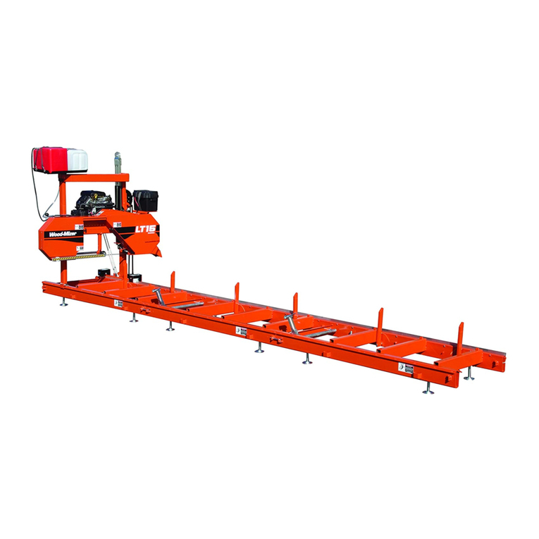
LT15 rev. A.00 - E8.13
Safety is our #1 concern! Read and understand
all safety information and instructions before oper-
ating, setting up or maintaining this machine.
April 2010
Form #884

©2019
Printed in the United States of America, all rights reserved. No part of this manual may be
reproduced in any form by any photographic, electronic, mechanical or other means or used in
any information storage and retrieval system without written permission from
Wood-Mizer
8180 West 10th Street
Indianapolis, Indiana 46214
&DOLIRUQLD
3URSRVLWLRQ:DUQLQJ
:$51,1*%UHDWKLQJJDVGLHVHOHQJLQHH[KDXVWH[SRVHV\RXWRFKHPLFDOVNQRZQWR
WKH6WDWHRI&DOLIRUQLDWRFDXVHFDQFHUDQGELUWKGHIHFWVRURWKHUUHSURGXFWLYHKDUP
$OZD\VVWDUWDQGRSHUDWHWKHHQJLQHLQDZHOOYHQWLODWHGDUHD
,ILQDQHQFORVHGDUHDYHQWWKHH[KDXVWWRWKHRXWVLGH
'RQRWPRGLI\RUWDPSHUZLWKWKHH[KDXVWV\VWHP
'RQRWLGOHWKHHQJLQHH[FHSWDVQHFHVVDU\
)RUPRUHLQIRUPDWLRQJRWRZZZ3ZDUQLQJVFDJRY
:$51,1*'ULOOLQJVDZLQJVDQGLQJRUPDFKLQLQJZRRGSURGXFWVFDQH[SRVH\RXWR
ZRRGGXVWDVXEVWDQFHNQRZQWRWKH6WDWHRI&DOLIRUQLDWRFDXVHFDQFHU$YRLGLQKDOLQJ
ZRRGGXVWRUXVHDGXVWPDVNRURWKHUVDIHJXDUGVIRUSHUVRQDOSURWHFWLRQ
)RUPRUHLQIRUPDWLRQJRWRZZZ3:DUQLQJVFDJRYZRRG

Table of Contents Section-Page
Table of Contents WMdoc091819 iii
TOC
SECTION 1 ABOUT THIS MANUAL 1-1
SECTION 2 OPERATION 2-1
2.1 Starting The Engine................................................................................2-1
SECTION 3 MAINTENANCE 3-1
3.1 Safety......................................................................................................3-1
3.2 Cooling System ......................................................................................3-2
3.3 Air Filter & Pre-Cleaner.........................................................................3-2
3.4 Fuel Filter ...............................................................................................3-2
3.5 RPM Adjustments ..................................................................................3-2
3.6 Miscellaneous Maintenance ...................................................................3-3
SECTION 4 REPLACEMENT PARTS 4-1
4.1 Engine Assembly....................................................................................4-1
LT15 Rev. E1.00+
4.2 Engine Assembly....................................................................................4-3
LT15 Rev. D4.00 - D7.00
4.3 Engine Assembly....................................................................................4-5
LT15 Rev. A1.00 - D3.00
4.4 Throttle/Clutch Assembly ......................................................................4-7
LT15 G13/G15 Rev. E1.00+
4.5 Throttle/Clutch Assembly ......................................................................4-9
LT15 Rev. D4.00 - D7.00
4.6 Throttle/Clutch Assembly ....................................................................4-11
LT15 Rev. D3.00
4.7 Throttle/Clutch Assembly ....................................................................4-13
LT15 Rev. A1.00 - D2.00
INDEX 1-I

About This Manual
1
1-1 WM doc 9/18/19 About This Manual
SECTION 1 ABOUT THIS MANUAL
This manual is provided as a supplement to the equipment manufacturer’s manuals. This
manual provides information specific to the use of this equipment on the Wood-Mizer®
sawmill. Refer to the sawmill operator’s manual and manufacturer's manual before
attempting to operate this equipment.
IMPORTANT! Read the sawmill operator’s manual and engine manu-
facturer’s manual for instructions and safety precautions before oper-
ating this equipment.
The information and instructions given in this manual do not amend or extend the limited
warranties for the equipment given at the time of purchase.

Operation
Starting The Engine
Operation WM doc 9/18/19 2-1
2
SECTION 2 OPERATION
2.1 Starting The Engine
DANGER! Ensure the blade is disengaged and all persons are out of
the path of the blade before starting. Failure to do so will result in death
or serious injury.
DANGER! Operate your engine only in well ventilated areas. The
exhaust gases of your engine can cause nausea, delirium, and
potentially death unless adequate ventilation is present.
DANGER! Never operate an engine with a fuel or oil leak. This is a
fire hazard, which may cause serious injury or death.
WARNING! Do not operate engine without proper and operational
spark arrester/muffler. Sparks emitted from the engine exhaust
could ignite surrounding materials, causing serious injury or death.
CAUTION! EPA Compliant Gas Tanks Only: Always relieve all fuel
pressure inside the tank prior to filling or connecting fuel fittings.
Failure to do so may result in fuel spillage.
CAUTION! EPA Compliant Gas Tanks Only: Disconnect the fuel tank
when not in use, or engine flooding or fuel spillage may result.
1. Turn the run/stop switch to the RUN position.
See Figure 2-1.
2. Close the engine choke by moving the choke lever to the start position.
FIG. 2-1 G13

Operation
Starting The Engine
2
2-2 WM doc 9/18/19 Operation
3. Pull the start rope slowly until you feel resistance, then pull the cord quickly to start the
engine. Repeat with the choke opened slightly if necessary.
NOTE: If the engine is hard to start with the throttle in the idle posi-
tion, push the throttle swivel plate down slightly and retry.
4. When the engine starts, slowly open the choke all the way by moving the choke lever to
the off position.
For more information, see the engine manufacturer’s operation manual.
ENGINE SHUTOFF
1. Disengage the clutch handle to stop the blade if necessary.
2. Let the engine run for 15 seconds with no load, then push the run/stop switch to STOP.

Maintenance
Safety
Maintenance WM doc 9/18/19 3-1
3
SECTION 3 MAINTENANCE
Refer to the manufacturer’s manual for maintenance intervals and procedures unless oth-
erwise instructed in this manual. Follow the manufacturer’s recommendations for dusty
conditions.
IMPORTANT! This manual only provides information about additional
procedures or procedures to be performed at different time intervals
than found in the manufacturer's manuals. Refer to the manufacturer's
manual for complete maintenance instructions.
WARNING! Clean sawdust from all guards, vents, control
boxes, or any area where sawdust may gather after every
shift. Failure to do so may result in fire, causing death or
serious injury.
3.1 Safety
Use caution when performing maintenance or service to the engine.
DANGER! Always be aware of and take proper protective measures
against rotating shafts, pulleys, fans, etc. Always stay a safe distance
from rotating members and make sure that loose clothing or long hair
does not engage rotating members resulting in possible injury.
DANGER! Engine components can become very hot during operation.
Avoid contact with any part of a hot engine. The exhaust components
of your engine are especially hot during and following operation. Con-
tact with hot engine components can cause serious burns. Therefore,
never touch or perform service functions on a hot engine. Allow the
engine to cool sufficiently before beginning any service function.
WARNING! Remove the blade before performing any engine service.
Failure to do so may result in serious injury.
WARNING! Always wear proper and necessary safety equipment
when performing service functions. Proper safety equipment includes
eye protection, breathing protection, hand protection and foot protec-
tion.
This symbol identifies the interval (hours of operation) at which each maintenance pro-
cedure should be performed. "AR" signifies maintenance procedures which should be
performed as required.
0

Maintenance
Cooling System
3
3-2 WM doc 9/18/19 Maintenance
3.2 Cooling System
Wash the engine or brush off sawdust and debris every 50 hours of operation. Clean the
grass screen, cooling fins, and external surfaces. Remove any dust, dirt or oil. See
engine manual for further instructions.
3.3 Air Filter & Pre-Cleaner
WARNING! Always wear proper and necessary safety equipment
when performing service functions. Proper safety equipment includes
eye protection, breathing protection, hand protection and foot protec-
tion.
Service the pre-cleaner every four hours of operation. Service by gently shaking excess
sawdust and debris from the foam piece.
Clean the air filter (air cleaner element) and pre-cleaner (element wrapper) every eight
hours of operation. See the engine manual for further instructions.
Replace the air filter (cleaner) every 200 hours of operation.
Replace the pre-cleaner (element wrapper) every 2000 hours of operation.
3.4 Fuel Filter
Replace the fuel filter every 100 hours of operation or as required for engine perfor-
mance.
3.5 RPM Adjustments
WARNING! Remove the blade before performing any engine service.
Failure to do so may result in serious injury.
Check the RPM with a tachometer every 200 hours of operation.
50
4
8
200
2000
100
200

Maintenance
Miscellaneous Maintenance
Maintenance WM doc 9/18/19 3-3
3
See Table 3-1.
Before checking the RPM, make sure belt and brake strap tensions are correct (See Saw-
mill Maintenance). Also check oil, fuel, and coolant levels.
Make sure the throttle cable does not affect the engine RPM when the clutch handle is
disengaged. Make sure the cable is not bent or kinked.
1. Start the engine to measure the low-end RPM.
2. Refer to the engine manual to adjust the low-end RPM.
3. Engage the clutch handle to throttle the engine and measure the high-end RPM. The
high-end RPM is factory-set at 3750. Readjust the throttle cable if necessary to increase
or reduce the high-end engine speed.
3.6 Miscellaneous Maintenance
Inspect the spark plugs every 100 hours of operation. Remove any deposits and adjust
gap if necessary. See engine manual for further information.
Review the manufacturer's engine manual for maintenance intervals.
Engine High End RPM Low End RPM
G13 3750 1800
TABLE 3-1
100

Replacement Parts
Engine Assembly
4
4-1 G1397doc091819 Replacement Parts
G13
SECTION 4 REPLACEMENT PARTS
4.1 Engine Assembly
LT15 Rev. E1.00+
REF DESCRIPTION ( Indicates Parts Available In Assemblies Only) PART # QTY.
Cover, Engine P12393 1
ENGINE ASSEMBLY, 13 HP KOHLER W/CLUTCH 034806 1
1Engine, 13 HP Kohler #PA22519 014809 1
2Filter, Kohler Air #47-083-01 014718 1
1
23
4
5
6
8
7
9
10
11
12
13
14
15
16
17
18
19
20
150145

Replacement Parts
Engine Assembly
Replacement Parts G1397doc091819 4-2
4
G13
3Pre-Cleaner, Kohler Air #52-083-01 014719 1
4Filter, Kohler Oil #28-050-01-S 036653 1 1
Filter, Kohler Oil #52-050-02 014717 1 1
Muffler Kit, G13 Kohler 016498 1
5Muffler, Kohler #12-068-39 016106 1 u
6Gasket, Kohler Muffler #12-041-03 016494 1
7Deflector, Kohler Flat #12-755-27 016497 1
8Arrestor, Kohler Spark #12-189-02 016495 1
9Guard, Kohler Muffler #12-314-11 016105 2 1
Plug, Kohler Spark #12-132-02 (Champion #RC12YC) P12757 1
Filter, Kohler In-Line Fuel #25-050-02 014720 1
Switch, Kohler PHI Oil #25-099-24-S 051992 1
Throttle and Clutch Parts (See Section 4.4)
10 Hose, Oil Drain P10082 1
11 Cap, Oil Drain Hose P04332 1
12 Plate, LT15 Engine Guard 016493 1
13 Sheave, BK55QT 016512 1
14 Key, 1/4” X 1 11/16” S04124 3 1
15 Bushing, QT x 1” 016513 1
16 BELT, BX87 DRIVE 017943 1
17 WASHER, 3/8” SAE FLAT F05011-3 4
18 WASHER, 3/8” SPLIT LOCK F05011-4 4
19 BOLT, 3/8-16 X 1 3/4” HEX HEAD GR5 F05007-119 4
20 Spacer, 17/32” x 1 1/2” x 3/4” 034641 4
1 Shorter Oil Filter 036653 required for LT15G13 Rev. E4.00 and later to avoid interference with up/down assist mechanism. Either
filter can be used for previous revisions.
2 No longer available (5/16). No replacement part available from Kohler or Wood-Mizer.
3 Replaces S21486 1/4” x 1” key. S04124 always used in production.

Replacement Parts
Engine Assembly
4
4-3 G1397doc091819 Replacement Parts
G13
4.2 Engine Assembly
LT15 Rev. D4.00 - D7.00
REF DESCRIPTION ( Indicates Parts Available In Assemblies Only) PART # QTY.
Cover, Engine P12393 1
ENGINE ASSY, 13 HP KOHLER W/CLUTCH 016517 1
1Engine, 13 HP Kohler #PA22519 014809 1
2Filter, Kohler Air #47-083-01 014718 1
3Pre-Cleaner, Kohler Air #52-083-01 014719 1
1
23
4
5
6
8
7
9
10
11
12
13
14
15
16
17
18
19
150081

Replacement Parts
Engine Assembly
Replacement Parts G1397doc091819 4-4
4
G13
4Filter, Kohler Oil #52-050-02 014717 1
Muffler Kit, G13 Kohler 016498 1
5Muffler, Kohler #12-068-39 016106 1 u
6Gasket, Kohler Muffler #12-041-03 016494 1
7Deflector, Kohler Flat #12-755-27 016497 1
8Arrestor, Kohler Spark #12-189-02 016495 1
9Guard, Kohler Muffler #12-314-11 016105 1 1
Plug, Kohler Spark #12-132-02 (Champion #RC12YC) P12757 1
Filter, Kohler In-Line Fuel #25-050-02 014720 1
Switch, Kohler PHI Oil #25-099-24-S 051992 1
Throttle and Clutch Parts (See Section 4.4)
10 Hose, Oil Drain P10082 1
11 Cap, Oil Drain Hose P04332 1
12 Plate, LT15 Engine Guard 016493 1
13 Sheave, BK55QT 016512 1
14 Key, 1/4” x 1 11/16” S04124 1
15 Bushing, QT x 1 016513 1
16 BELT, BX82 DRIVE 016505 1
17 WASHER, 3/8” SAE FLAT F05011-3 4
18 WASHER, 3/8” SPLIT LOCK F05011-4 4
19 BOLT, 3/8-16 X 1” HEX HEAD F05007-7 4
1 No longer available (5/16). No replacement part available from Kohler or Wood-Mizer.

Replacement Parts
Engine Assembly
4
4-5 G1397doc091819 Replacement Parts
G13
4.3 Engine Assembly
LT15 Rev. A1.00 - D3.00
REF DESCRIPTION ( Indicates Parts Available In Assemblies Only) PART # QTY.
Cover, Engine P12393 1
ENGINE ASSY, 13 HP KOHLER W/CLUTCH 014801 1
1Engine, 13 HP Kohler #PA22519 014809 1
2Filter, Kohler Air #47-083-01 014718 1
1
2
3
4
5
7
9
8
6
10
11
12
13 14
14
17
18
19
20
21 22
23
15
16
24
150058E

Replacement Parts
Engine Assembly
Replacement Parts G1397doc091819 4-6
4
G13
3Pre-Cleaner, Kohler Air #52-083-01 014719 1
4Filter, Kohler Oil #52-050-02 014717 1
Muffler Kit, G13 Kohler 016498 1
5Muffler, Kohler #12-068-39 016106 1 1u
6Gasket, Kohler Muffler #12-041-03 016494 1
7Deflector, Kohler Flat #12-755-27 016497 1
8Arrestor, Kohler Spark #12-189-02 016495 2 1
9Guard, Kohler Muffler #12-314-11 016105 3 1
Plug, Kohler Spark #12-132-02 (Champion #RC12YC) P12757 1
Filter, Kohler In-Line Fuel #25-050-02 014720 1
Switch, Kohler PHI Oil #25-099-24-S 051992 1
10 Bracket Weldment, Throttle Mount/Switch Mount 015441 1
11 Switch, Engine Stop/Run 015444 1
12 Terminal, 1/4” 14-16 Ga Quick Female FI F05708-3 2
13 Terminal, 1/4” 14-16 Ga Ring NI Loose F05092-2 1
14 Throttle and Clutch Parts (See Section 4.4)
15 Hose, Oil Drain P10082 1
16 Cap, Oil Drain Hose P04332 1
17 Plate, G13 Engine Mount 014810 1
18 Washer, 3/8” SAE Flat F05011-3 4
19 Washer, 3/8” Split Lock F05011-4 4
20 Bolt, 3/8-16 x 1” Hex Head F05007-7 4
21 BOLT, 3/8-16 X 1 1/4” SPRING WASHER LOCK HEX HEAD F05007-131 4
22 ROD, BELT TENSION ADJUSTMENT 014975 1
23 NUT, 3/8-16 HEX F05010-1 2
24 BELT, BX81 014819 1
1 Use muffler kit 016498 for service. Kit includes gasket, deflector and spark arrestor. Muffler 016106 no longer a sellable item (3/00).
2 Spark arrestor 016495 replaces 016146 originally supplied prior to 3/00 (duplicate parts).
3 No longer available (5/16). No replacement part available from Kohler or Wood-Mizer.

Replacement Parts
Throttle/Clutch Assembly
4
4-7 G1397doc091819 Replacement Parts
G13
4.4 Throttle/Clutch Assembly
LT15 G13/G15 Rev. E1.00+
REF DESCRIPTION ( Indicates Parts Available In Assemblies Only) PART # QTY.
1 PLATE, THROTTLE CABLE BRACKET LT15G 034616 1
2 SCREW, 1/4-20 X 3/4 FT HEX HEAD F05005-1 1
3 NUT, 1/4-20 NYLON LOCK F05010-69 1
4 SPRING, EXTENSION 3/8 X 3 014818 1
5 PIVOT WELDMENT, THROTTLE LT15G 034805 1
6 BOLT, 1/4-20 X 2 HEX HEAD GR5 F05005-125 1
7 NUT, 1/4-20 SWAGED F05010-21 2
8 LINK, THROTTLE 2 13/16 015446 1
9 CABLE ASSEMBLY, LT15G15 THROTTLE 034838 1
10 KNOB, 5/8-11 BALL P04211 1
11 HANDLE, LT15 CLUTCH 016487 1
12 SCREW, 3/8-16 X 1/2 SOCKET HEAD CUP PT SET F05007-12 2
13 ACTUATOR WELDMENT, THROTTLE LT15D&G 034815 1
14 LINKAGE, THROTTLE LT15D&G 034818 1
150098F
1
2
3
4
5
6
7
78
9
10
11
13
12
12
14
15
16
17
17
18 19
20
22
24
23
25
26
26
27
28
29
30 31
32
33 34
39
38
35
35
37
36
36

Replacement Parts
Throttle/Clutch Assembly
Replacement Parts G1397doc091819 4-8
4
G13
15 BOLT, 1/4-20 X 1/2” HEX HEAD F05005-15 1
16 NUT, 1/4-20 SWAGED F05010-21 1
17 BUSHING, 5/8” ID X 7/8” OD X 1 1/8” LONG FLANGED BRONZE 016486 2
18 BLOCK WELDMENT, LINKAGE CLUTCH/BRAKE 034612 1
19 PIN, 3/16 X 1 1/4 ROLL F05012-16 1
20 LINKAGE ASSEMBLY, W/BEARING 034605 1
21 Bushing, 5/8” ID x 7/8” OD x 1 1/8” Long Flanged Bronze 016486 1
22 NUT, 1/2-13 FREE HEX, ZINC F05010-35 1
23 WASHER, 1/2 SPLIT LOCK F05011-9 1
24 NUT, 1/2-13 JAM F05010-31 1
25 PIVOT WELDMENT, CLUTCH/BRAKE 034608 1
26 BUSHING, 1 X 1 1/4 X 3/4 FLG BRONZE P737 2
BRAKE/CLUTCH ASSEMBLY, LT15 034603 1
27 Arm Weldment, Clutch/Brake LT15 034613 1
28 Bolt, 3/8-16 x 2 Hex Head Gr5 F05007-124 1
29 Nut, 3/8-16 Hex Nylon Lock F05010-10 1
30 Block, LT15 Brake 016488 2
31 Screw, 10-24 x 1” Socket Head F05004-2 1 4
32 Nut, #10-24 Keps F05010-14 4
33 Idler, 4" O.D. x 3/8 Bore 034602 1
34 Bolt, 3/8-16 x 2-3/4” Hex Head Gr5 Full Thread F05007-230 1
35 Washer, 3/8 Flat F05011-3 2
36 Nut, 3/8-16 Swaged Lock F05010-25 2
37 Spring, Idler Arm LT15/D/E/G 034810 1
1 Replaces F05004-50 originally supplied before 4/03 (duplicate part numbers).

Replacement Parts
Throttle/Clutch Assembly
4
4-9 G1397doc091819 Replacement Parts
G13
4.5 Throttle/Clutch Assembly
LT15 Rev. D4.00 - D7.00
REF DESCRIPTION ( Indicates Parts Available In Assemblies Only) PART # QTY.
1 PLATE, BRAKE ACTUATOR 016470 1
2 BOLT, 5/16-24 X 1” HEX HEAD F05006-11 2
3 WASHER, 5/16” SPLIT LOCK F05011-13 2
4 NUT, 1/4-20 SWAGED F05010-21 2
5 WASHER, 1/4” SAE FLAT F05011-11 6
6 PIVOT WELDMENT, THROTTLE LT15 016503 1
7 SPRING, 3/8” X 3“ EXTENSION 014818 1
8 WIRE, THROTTLE LT15 014826 1
9 BOLT, 1/4-20 X 2” HEX HEAD GRADE 5 F05005-125 1
10 SCREW, 1/4-20 X 1 3/4” HEX HEAD CAP F05005-4 1
11 NUT, 1/4-20 KEPS F05010-9 2
12 KNOB, 5/8-18 PLASTIC ROUND P04211 1
4
4
355
5
5
45
5
6
7
8
2
1
15
16
16 15
10
11
13
14
16
16
22
21
20
18
17
42
43
46
44
11 11
41
40
39
150080B
36
38 37
35
24
25
28
23
30
31
32
33
34
26
29 27
20
19 12
11
9
29

Replacement Parts
Throttle/Clutch Assembly
Replacement Parts G1397doc091819 4-10
4
G13
13 HANDLE, LT15 CLUTCH 016487 1 1
14 PIN, 3/16 X 1 1/4” ROLL F05012-16 1
15 BUSHING, 5/8” ID X 7/8” OD X 1 1/4” LONG FLANGED BRONZE 016486 2
16 BUSHING, 3/4” ID X 1” OD X 1 1/8” LONG FLANGED BRONZE 016485 4
17 PIN WELDMENT, MOTOR PIVOT 016477 1
18 NUT, 3/8-16 SWAGED LOCK F05010-25 1
19 BOLT, 3/8-16 X 3/4” HEX HEAD GRADE 2 F05007-27 1
20 SCREW, 7/16-20 X 1 1/2” SOCKET HEAD CAP F05007-55 2
21 WASHER, 7/16” SAE FLAT 15/16” OD F05011-43 1
22 BLOCK, MOTOR HANDLE PIVOT 016481 1
TURNBUCKLE ASSEMBLY, CLUTCH A12304 1
23 Nut, 7/16-20 Jam F05010-38 1
24 Rod End, 7/16-20 Right Hand Male P11579 1
25 Turnbuckle, 3" Clutch S11577 1
26 Nut, 7/16-20 Left Hand Jam F05010-87 1
27 Rod End, 7/16-20 Left Hand Male P11578 1
28 NUT, 7/16-20 JAM F05010-38 1
29 WASHER, 7/16” SPLIT LOCK F05011-48 3
30 NUT, 3/8-16 HEX NYLON LOCK F05010-10 2
31 WASHER, 3/8” FLAT SAE F05011-3 6
32 PLATE, LOWER TURNBUCKLE MOUNT 016472 1
33 NUT, 7/16-20 NYLON LOCK F05010-83 1
34 BOLT, 3/8-16 X 4 1/2” HEX HEAD F05007-35 2
35 SCREW, 10-24 X 1 1/2” SOCKET HEAD CAP BLACK OXIDE F05004-51 4
36 BLOCK, LT15 BRAKE 016488 2
37 NUT, #10-24 KEPS F05010-14 4
38 PIN, IDLER PIVOT 040102 1
39 PIN, 1/4” DIA LYNCH P113 1
40 SCREW, 1/4-20 X 1” HEX HEAD CAP F05005-38 1
41 SPRING, 3/8” OD X 4 1/2” LONG X .047” WIRE EXTENSION 016508 1
42 NUT, 1/2-13 JAM F05010-31 1
43 BOLT, 1/2-13 X 2” HEX HEAD GRADE 5 F05008-8 2 1
44 PLATE WELDMENT, BRAKE 016482 1
45 SPRING, EXTENSION 1/2” X 2 1/4” X .06” 014817 1
46 PLATE, LT15 MOTOR MOUNT 016473 1
1 Clutch Handle 016487 modified 3/07 to eliminate possible pinch point with feed rope pulley with saw head at certain heights.
2 Replaces F05008-33 1/2-13 x 1 1/2” Hex Head Bolt supplied prior to 10/00. Longer bolt provides more brake adjustment.

Replacement Parts
Throttle/Clutch Assembly
4
4-11 G1397doc091819 Replacement Parts
G13
4.6 Throttle/Clutch Assembly
LT15 Rev. D3.00
REF DESCRIPTION ( Indicates Parts Available In Assemblies Only) PART # QTY.
1 HANDLE, THROTTLE/CLUTCH 014825 1
2 GRIP, 1/2” I.D. X 3” LONG HANDLE 014835 1
3 COLLAR, 1/2” I.D. X 7/8” O.D. LOCK 014820 1
4 BUSHING, SF1260-6 BRONZE P08060 2
5 BRACKET, THROTTLE/CLUTCH HANDLE MOUNT 014821 1
6 BRACKET, THROTTLE/CLUTCH HANDLE PIVOT 014837 1
7 PIN, 3/16” X 5/8” ROLL F05012-22 1
8 PLATE, THROTTLE MOUNT 014813 1
9 BOLT, 5/16-18 X 1 1/4” HEX HEAD FULL THREAD F05006-18 1
10 NUT, 5/16-18 HEX NYLON LOCK F05010-58 4
11 WASHER, 3/8” SPLIT LOCK F05011-4 2
12 BOLT, 3/8-16 X 3/4” HEX HEAD GRADE 2 F05007-27 2
13 SPRING, 1/2” X 2 1/4” X .06” EXTENSION 014817 1
14 BRACKET WELDMENT, THROTTLE PIVOT 014836 1
15 NUT, 1/4-20 HEX LOCK F05010-21 2
16 WASHER, 1/4” SAE FLAT F05011-11 2
17 SPRING, 3/8” X 3” EXTENSION 014818 1
18 WIRE, THROTTLE 014826 1
19 BOLT, 1/4-20 X 1 3/4” HEX HEAD GRADE 2 F05005-4 1
20 BOLT, 1/4-20 X 1” HEX HEAD GRADE 2 F05005-38 1
21 NUT, 1/4-20 SELF-LOCKING HEX F05010-9 2
22 BOLT, 5/16-18 X 1 1/2” HEX HEAD GRADE 5 FULL THREAD F05006-76 1
25
26
27
28
150058-2
1
2
3
4
4
5
6
7
8
9
10
10
11
12
13
14
15
16
17
18
19
11
12
20
10
21
22
29
24
28
29
30
31
23
32
33
36
37 34 35
38
Other manuals for G13
2
Table of contents
Other woodmizer Engine manuals

woodmizer
woodmizer D19 Guide

woodmizer
woodmizer D24 Guide

woodmizer
woodmizer G14 Guide

woodmizer
woodmizer LT30 Super Guide

woodmizer
woodmizer D42 Guide

woodmizer
woodmizer LT35 Guide

woodmizer
woodmizer LT28 D17 Guide

woodmizer
woodmizer D35 Series Guide

woodmizer
woodmizer LT28 G19 Guide

woodmizer
woodmizer D42 Guide

woodmizer
woodmizer D17 Guide

woodmizer
woodmizer D10 Guide

woodmizer
woodmizer G18 LT20 Series Guide

woodmizer
woodmizer LT28 G25 Guide

woodmizer
woodmizer D42 Guide

woodmizer
woodmizer LT40 MH Series Guide

woodmizer
woodmizer D42 Guide

woodmizer
woodmizer D34 Guide

woodmizer
woodmizer D17 Guide

woodmizer
woodmizer G15 Guide