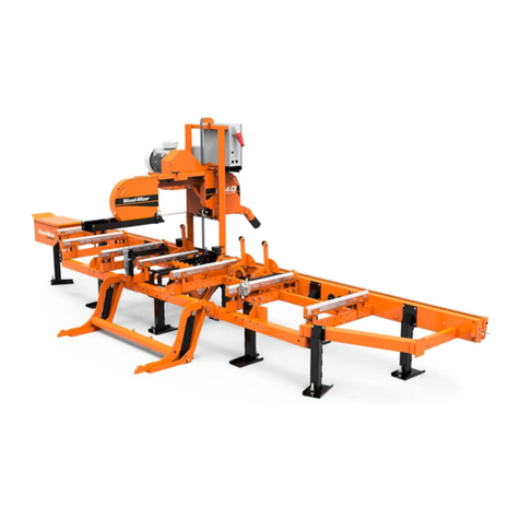
woodmizer LT28 D17 Guide

LT28 D17 Engine
Safety, Operation, Maintenance
& Parts Manual
LT28D17 rev. A6.00 - A6.15 only
Safety is our #1 concern! Read and understand
all safety information and instructions before oper-
ating, setting up or maintaining this machine.
October 2009
Form #1633

Active Patents assigned to Wood-Mizer, LLC
Wood-Mizer, LLC has received patents that protect our inventions which are a result of a dedication to
research, innovation, development, and design. Learn more at: woodmizer.com/patents
©2022 Wood-Mizer LLC
Printed in the United States of America, all rights reserved. No part of this manual may be reproduced in any form by
any photographic, electronic, mechanical or other means or used in any information storage and retrieval system with-
out written permission from
Wood-Mizer, LLC
8180 West 10th Street
Indianapolis, Indiana 46214
California
Proposition 65 Warning
WARNING:
Breathing gas/diesel engine exhaust exposes you to chemicals known to
the State of California to cause cancer and birth defects or other reproductive harm.
Always start and operate the engine in a well-ventilated area.
If in an enclosed area, vent the exhaust to the outside.
Do not modify or tamper with the exhaust system.
Do not idle the engine except as necessary.
For more information go to www.P65warnings.ca.gov.
WARNING:
Drilling, sawing, sanding or machining wood products can expose you to
wood dust, a substance known to the State of California to cause cancer. Avoid inhaling
wood dust or use a dust mask or other safeguards for personal protection.
For more information go to www.P65Warnings.ca.gov/wood.

Table of Contents Section-Page
Table of Contents WMdoc091622 iii
TOC
SECTION 1 ABOUT THIS MANUAL 1-1
SECTION 2 OPERATION 2-1
2.1 Starting The Engine................................................................................2-1
SECTION 3 MAINTENANCE 3-1
3.1 Maintenance ...........................................................................................3-1
3.2 Safety......................................................................................................3-1
3.3 Battery ....................................................................................................3-1
3.4 Fuel Filter ...............................................................................................3-2
SECTION 4 REPLACEMENT PARTS 4-1
4.1 Fuel Tank................................................................................................4-1
5.2 Engine Assembly....................................................................................5-1
6.3 Throttle/Clutch Assembly ......................................................................6-1

1
1-1 WM doc 9/16/22
SECTION 1 ABOUT THIS MANUAL
This manual is provided as a supplement to the equipment manufacturer’s manuals. This manual provides information specific
to the use of this equipment on the Wood-Mizer® sawmill. Refer to the sawmill operator’s manual and manufacturer's manual
before attempting to operate this equipment.
IMPORTANT! Read the sawmill operator’s manual and engine manufacturer’s man-
ual for instructions and safety precautions before operating this equipment.
The information and instructions given in this manual do not amend or extend the limited warranties for the equipment given at
the time of purchase.

Operation
Starting The Engine 2
Operation WM doc 9/16/22 2-1
SECTION 2 OPERATION
2.1 Starting The Engine
DANGER! Always be sure the blade is disengaged and clear the path of the blade
before starting the engine. Failure to do so will result in serious injury or death.
DANGER! Operate your engine/machine only in well ventilated areas.Exhaust gases
can cause nausea, delirium and potentially death unless adequate ventilation is pres-
ent.
DANGER! Never operate an engine with a fuel or oil leak. The leaking fuel or oil could
potentially come in contact with hot surfaces and ignite into flames.
WARNING! Do not operate engine without proper and operational spark arrester/muf-
fler. Sparks emitted from the engine exhaust could ignite surrounding materials, caus-
ing serious injury or death.
1. See the engine manufacturer’s manual for lubricating oil recommendations for specific temperature ranges.
2. Use #2 or better quality diesel fuel for above freezing starting. Use a #1 quality diesel fuel for below freezing starting.
3. Turn the key switch to the on (#1) position.
4. Turn the key switch to the start (#2) position and release.
ENGINE SHUTOFF
1. Disengage the clutch handle to stop the blade if necessary.
2. Turn the key switch to the off (#0) position.

Maintenance
Maintenance
3
3-1 WM doc 9/16/22 Maintenance
SECTION 3 MAINTENANCE
3.1 Maintenance
Refer to the manufacturer’s manual for maintenance intervals and procedures unless otherwise instructed in this manual. Fol-
low the manufacturer’s recommendations for dusty conditions.
IMPORTANT! This manual only provides information about additional proce-
dures or procedures to be performed at different time intervals than found in
the manufacturer's manuals. Refer to the manufacturer's manual for complete
maintenance instructions.
WARNING! Clean sawdust from all guards, vents, control boxes, or any
area where sawdust may gather after every shift. Failure to do so may
result in fire, causing death or serious injury.
3.2 Safety
Use caution when performing maintenance or service to the engine.
DANGER! Always be aware of and take proper protective measures against
rotating shafts, pulleys, fans, etc. Always stay a safe distance from rotating
members and make sure that loose clothing or long hair does not engage
rotating members resulting in possible injury.
DANGER! Engine components can become very hot during operation. Avoid
contact with any part of a hot engine. The exhaust components of your engine
are especially hot during and following operation. Contact with hot engine
components can cause serious burns. Therefore, never touch or perform ser-
vice functions on a hot engine. Allow the engine to cool sufficiently before
beginning any service function.
WARNING! Remove the blade before performing any engine service. Failure
to do so may result in serious injury.
WARNING! Always wear proper and necessary safety equipment when per-
forming service functions. Proper safety equipment includes eye protection,
breathing protection, hand protection and foot protection.
3.3 Battery
Check the battery electrolyte level every 50 hours of operation. See manufacturer’s manual for instructions.
DANGER! Batteries expel explosive gases. Keep sparks, flames, burning cig-
arettes, or other ignition sources away at all times. Always wear safety gog-
gles and a face shield when working near batteries. Failure to do so will cause
serious injury.
WARNING! Battery posts, terminals and related accessories contain lead and
lead compounds, chemicals known to the State of California to cause cancer
and reproductive harm. Wash hands after handling.

Maintenance
Fuel Filter 3
Maintenance WM doc 9/16/22 3-2
3.4 Fuel Filter
Replace the fuel filter every 100 hours of operation or as required for engine performance.

Replacement Parts
Fuel Tank
4
4-1 WM doc 9/16/22 Replacement Parts
SECTION 4 REPLACEMENT PARTS
4.1 Fuel Tank
REF PART # DESCRIPTION COMMENTS QTY.
074829 TRAY ASSEMBLY, LT28/35 FUEL TANK 1
1103810 Weldment, Fuel Tank Tray 1
2103867 Cover, Fuel Tank 1
103928 Tank, 5 Gallon Low Pro Diesel 1
3061257 Cap, Fuel Tank Diesel 080185BE 1
4061255 Fitting, Pick-Up/Tube Diesel 468871A 1
5061250 Grommet, Shut Off 046881 2
6061256 Fitting, Return/tube Diesel 468489 1
7F05006-15 Bolt, 5/16-18 x 1/2” Hex Head Grade 5 4
8F05007-73 Bolt, 3/8-16 x 3” Hex Head Grade 5 3
9F05010-10 Nut, 3/8-16 Hex Nyloc 3
10 F05011-3 Washer, 3/8” Flat SAE 6
11 F05011-13 Washer, 5/16 Split Lock 4
12 F05011-17 Washer, 5/16 SAE Flat 4
R02423-1 Hose, Fuel 3/16" EPA 15G CARB R02423-1 replaced R02423-3
after 2/1/2021 per ECN 37794.
6 Ft
R02423-3 Hose, Fuel 5/16" EPA 15G CARB 6 Ft
R02423-2 Hose, Fuel 1/4" EPA 15G CARB 6 Ft
1
2
3
9
8
4
5
6
7
10
11 12
280062B
5

Replacement Parts WM doc 9/16/22 5-1
Replacement Parts
Engine Assembly 5
5.2 Engine Assembly
REF PART # DESCRIPTION COMMENTS QTY.
007333 ENGINE ASSEMBLY, LT15 17HP DIESEL 1
1007332 Engine, 17HP Kohler Diesel Model KDW702 Available in assemblies only. 1
2007401 Filter Assembly, Kohler
#ED0037004550-S
1
007613 Filter, Kohler Secondary Air
#ED0021751250-S
1
007408 Filter, Kohler Primary Air
#ED0021751240-S
1
007614 Motor, Kohler Starter #ED0058402240-S 1
065408 Alternator, Kohler 65A
#ED0011572700-S
1
065409 Belt, Kohler Fan #ED0024403160-S 1
061187 Filter, Kohler/Lombardini Oil
#ED0021752830-S
1
061188 Filter, Kohler/Lombardini Fuel
#ED0021752880-S
1
014557 Switch Kit, Oil Pressure w/Gasket 1
014279 Switch, Diesel Fuel Shut-Off 1
014289 Pump, Diesel Fuel 1
1
3
2
4
5
5
6
7
8
9
8
7
10
11
12
13
14
15
16
17
18
20
21
22
19
23
25
26
27
28 29 30
30
34
35
36
37
150174-1C
24
31
32
33
38

Replacement Parts
Engine Assembly
5
5-2 WM doc 9/16/22 Replacement Parts
014278 Plug, Diesel Glow 2
3062308 Bracket, Air Filter Mount 1
4F05006-18 Bolt, 5/16-18 x 1 1/4” Hex Head Full Thread 2
5F05011-17 Washer, 5/16” SAE Flat 4
6F05010-20 Nut, 5/16-18 Self-Locking Hex 2
7P09895 Clamp, 2 1/2” Hose 4
8007394 Elbow, 90° x 2” ID Rubber 2
9007395 Tube, 1 3/4” ID x 2” OD x 4” 1
10 007392 Cable, LT15 D18 1
11 007465 Guard Weldment, D18 Radiator 1
12 F05011-11 Washer, 1/4” SAE Flat 6
13 F05011-14 Washer, 1/4” Split Lock 6
14 F05004-219 Bolt, M6 x 1.0 x 16mm Hex Head 6
15 007427 Bracket Weldment, Rear D18 Mount 1
16 F05004-251 Bolt, M12 x 1.75 x 20mm Hex Head Full
Thread
2
17 F05011-3 Washer, 3/8” SAE Flat 8
18 F05007-123 Bolt, 3/8-16 x 1 1/4” Hex Head Grade 5 4
19 F05010-10 Nut, 3/8-16 Hex Nylon Lock 4
20 007426 Bracket, D18 Front Mount 1
21 F05006-27 Bolt, 5/16-18 x 1” Hex Head Grade 5 2
22 F05010-58 Nut, 5/16-18 Hex Nylon Lock 2
23 014024 Shaft, Diesel Engine Drive 1
24 F05011-88 Washer, 10mm Split Lock 8
25 F81003-11 Bolt, M10-1.5 x 24mm Hex Head Grade 8.8 8
26 047742 Sheave, 3V5.6 x 2-SH 1
27 007338 Bushing, SH - 1 9/16” 1
28 007336 Guard Weldment, Motor Pulley 1
29 007344 Cover, Engine Pulley Guard 1
30 F05005-134 Bolt, 1/4-20 x 3/4” Hex w/Conical Washer
Head
4
31 065163 Fitting, M18 x 3/8” NPT Adaptor 1
32 P10082 Hose, 3/8” NPT x 9 5/8” Rubber 1
33 P04332 Fitting, 3/8” Galvonized Pipe Cap 1
34 047751 BELT, 2/3VFL900 DRIVE 1
35 048237 SUPPORT WELDMENT, DRIVE BELT 1
36 F05007-118 BOLT, 3/8-16 X 3/4” HEX HEAD GRADE 5 1
074947 panel, front D17 yanmar 1
REF PART # DESCRIPTION COMMENTS QTY.
37 F05010-19 NUT, 3/8-16 SELF-LOCKING HEX 1
007402 Rain cap d17 1
38
Replacement Parts WM doc 9/16/22 6-1
Replacement Parts
Throttle/Clutch Assembly 6
6.3 Throttle/Clutch Assembly
REF PART # DESCRIPTION COMMENTS QTY.
1065574 BLOCK WELDMENT, LINKAGE CLUTCH/BRAKE 1
2F05012-16 PIN, 3/16” X 1 1/4” ROLL 1
3016486 BUSHING, 5/8” ID X 7/8” OD X 1 1/4” LONG FL
BRONZE
2
4049340 SHAFT, LT28 THROTTLE 1
5034815 ACTUATOR WELDMENT, THROTTLE LT15D&G 1
6F05007-68 SCREW, 3/8-16 X 3/8” SOCKET HEAD CUP PT
SET
2
7034818 LINKAGE, THROTTLE LT15D&G 1
8F05005-15 BOLT, 1/4-20 X 1/2” HEX HEAD 1
9F05010-21 NUT, 1/4-20 SWAGED 1
10 P737 BUSHING, 1” X 1 1/4” X 3/4” FLANGED BRONZE 2
11 034608 PIVOT WELDMENT, CLUTCH/BRAKE 1
034605 LINKAGE ASSEMBLY, W/BEARING 1
12 034604 Boss Weldment, Clutch/Brake Linkage 1
13 016486 Bushing, 5/8” ID x 7/8” OD x 1 1/4” Long
Flanged Bronze
1
038778 NUT ASSEMBLY, 1/2-13 SPRING LOCKING 1
14 F05010-31 Nut, 1/2-13 Hex Jam 1
15 038777 Nut, 1/2-13 Spring Lock 1
16 046975 Spring, .72” OD x .576” ID x 1.25L Compression 1
17 F05010-127 Nut, 1/2-13 Half Nylon Lock 1
1
2
3
13
4
3
5
9
8
7
6
10
10
11
12
14
17
18 19
20
21
22
20
23
21
24
25
33
32
26
27
28
31
30 29
280059-2D
15
16

Replacement Parts
Throttle/Clutch Assembly
6
6-2 WM doc 9/16/22 Replacement Parts
065874 BRAKE/CLUTCH ASSEMBLY 1
18 065873 Arm Weldment, Clutch/Brake 1
19 F05007-124 Bolt, 3/8-16 x 2 Hex Head Grade 5 1
20 F05010-10 Nut, 3/8-16 Hex Nyl Lock 2
21 F05011-3 Washer, 3/8” Flat SAE 3
22 F05010-25 Nut, 3/8-16 Swaged 1
23 034810 Spring, Idler Arm LT15/D/E/G 1
24 034602 Idler, 4" O.D. x 3/8” Bore 1
25 F05007-125 Bolt, 3/8-16 x 2-1/2” Hex Head Grade 5 1
26 016488 Block, LT15 Brake 2
27 F05004-2 Bolt, #10-24 x 1” Socket Head Cup 4
28 F05010-14 Nut, #10-24 Keps 8
29 F05004-282 Screw, 10-24 x 5/8” FSHC 4
30 065872 Plate, Brake Adjustment 2
31 F05011-18 Washer, #10 SAE Flat 4
32 F05010-29 NUT, 3/8-16 JAM 1
33 F05007-18 SCREW, 3/8-16 X 1 1/4 SHOP SET 1
REF PART # DESCRIPTION COMMENTS QTY.
Other manuals for LT28 D17
1
Table of contents
Other woodmizer Engine manuals

woodmizer
woodmizer LT35 Guide

woodmizer
woodmizer LT28 Guide

woodmizer
woodmizer G13 Guide

woodmizer
woodmizer G18 LT20 Series Guide

woodmizer
woodmizer D35 Series Guide

woodmizer
woodmizer D10 Guide

woodmizer
woodmizer G14 Guide

woodmizer
woodmizer LT40 MH Series Guide

woodmizer
woodmizer D24 Guide

woodmizer
woodmizer G18 LT30 Guide