manuals.online logo
Brands
  1. Home
  2. •
  3. Brands
  4. •
  5. Woodward
  6. •
  7. Control System
  8. •
  9. Woodward 505E User manual

Woodward 505E User manual

Product Manual 85018V1
(Revision E)
Original Instructions
505E Digital Governor
for Extraction Steam Turbines
Volume 1
Manual 85018 consists of 2 volumes (85018V1 & 85018V2).
Installation and Operation Manual
General
Precautions
Read this entire manual and all other publications pertaining to the work to be
performed before installing, operating, or servicing this equipment.
Practice all plant and safety instructions and precautions.
Failure to follow instructions can cause personal injury and/or property damage.
Revisions
This publication may have been revised or updated since this copy was produced.
To verify that you have the latest revision, check manual 26311 , Revision Status &
Distribution Restrictions of Woodward Technical Publications, on the publications
page of the Woodward website:
www.woodward.com/publications
The latest version of most publications is available on the publications page. If
your publication is not there, please contact your customer service representative
to get the latest copy.
Proper Use
Any unauthorized modifications to or use of this equipment outside its specified
mechanical, electrical, or other operating limits may cause personal injury and/or
property damage, including damage to the equipment. Any such unauthorized
modifications: (i) constitute "misuse" and/or "negligence" within the meaning of
the product warranty thereby excluding warranty coverage for any resulting
damage, and (ii) invalidate product certifications or listings.
Translated
Publications
If the cover of this publication states "Translation of the Original Instructions"
please note:
The original source of this publication may have been updated since this
translation was made. Be sure to check manual 26311 , Revision Status &
Distribution Restrictions of Woodward Technical Publications, to verify whether
this translation is up to date. Out-of-date translations are marked with . Always
compare with the original for technical specifications and for proper and safe
installation and operation procedures.
Revisions—Changes in this publication since the last revision are indicated by a black line
alongside the text.
Woodward reserves the right to update any portion of this publication at any time. Information provided by Woodward is
believed to be correct and reliable. However, no responsibility is assumed by Woodward unless otherwise expressly
undertaken. © Woodward 1997
All Rights Reserved
Manual 85018V1 505E Digital Governor
Woodward i
Contents
WARNINGS AND NOTICES........................................................................... VI
ELECTROSTATIC DISCHARGE AWARENESS .................................................VII
REGULATORY COMPLIANCE ......................................................................VIII
CHAPTER 1. GENERAL INFORMATION...........................................................1
Introduction.............................................................................................................1
General Description................................................................................................3
505E Inputs and Outputs........................................................................................4
Control Overview ....................................................................................................8
Speed Control.......................................................................................................10
Auxiliary Control ...................................................................................................11
Load Sharing Input ...............................................................................................12
Cascade Control...................................................................................................12
Extraction/Admission Control ...............................................................................13
Ratio/Limiter .........................................................................................................13
HP and LP Valve Limiters.....................................................................................14
Starting Features ..................................................................................................15
Keypad and Display..............................................................................................21
Watchdog Timer/CPU Fault Control.....................................................................23
CHAPTER 2. INSTALLATION PROCEDURES..................................................24
Introduction...........................................................................................................24
Mechanical Data and Hardware Installation.........................................................24
CHAPTER 3. 505E CONTROL DESCRIPTION................................................42
Introduction...........................................................................................................42
Ratio/Limiter Configurations .................................................................................42
Speed vs. Extr/Adm Priority..................................................................................49
Turbine Start.........................................................................................................51
Turbine Start Modes .............................................................................................52
Critical Speed Avoidance .....................................................................................55
Idle/Rated .............................................................................................................56
Automatic Start Sequence....................................................................................58
No Idle Programmed ............................................................................................60
Speed Control Overview.......................................................................................60
Speed PID Operational Modes.............................................................................61
Synchronization ....................................................................................................70
Extraction and/or Admission Turbine Control.......................................................73
Extraction Control .................................................................................................75
ADMISSION or EXTR/ADM Control.....................................................................76
Remote Extr/Adm Setpoint...................................................................................79
Cascade Control...................................................................................................81
Remote Cascade Setpoint....................................................................................85
Auxiliary Control ...................................................................................................87
Valve Limiters .......................................................................................................92
Emergency Shutdown ..........................................................................................94
Controlled Shutdown ............................................................................................94
Overspeed Test Function .....................................................................................95
Local / Remote Function.......................................................................................96
Function Keys.......................................................................................................97
Relays...................................................................................................................98
505E Digital Governor Manual 85018V1
ii Woodward
Contents
CHAPTER 4. CONFIGURATION PROCEDURES ............................................101
Program Architecture..........................................................................................101
Programming the 505E.......................................................................................103
Exiting the Program Mode ..................................................................................138
Valve / Actuator Calibration and Test.................................................................141
CHAPTER 5. 505E OPERATION.................................................................146
Run Mode Architecture.......................................................................................146
Keypad and Display............................................................................................149
Run Mode Front Panel Keys ..............................................................................150
Starting Procedures............................................................................................151
Overspeed Test Function ...................................................................................155
F3 and F4 Keys ..................................................................................................157
Limiter (LMTR) Key Screens ..............................................................................157
Actuator (ACTR) Key Screens............................................................................159
Control (CONT) Key Screens .............................................................................160
Dynamics (DYN) Key Screens ...........................................................................162
Stop Key Screens...............................................................................................163
Auxiliary (AUX) Key Screens..............................................................................164
Remote / Speed Bias (RMT) Key Screens.........................................................167
Cascade (CAS) Key Screens .............................................................................170
Extraction/ Admission (EXT/ADM) Key Screens ................................................173
Alarms.................................................................................................................176
Trips....................................................................................................................178
Speed, Casc, Aux, and Ext/Adm Dynamics Adjustments ..................................179
CHAPTER 6. COMMUNICATIONS................................................................183
Modbus Communication.....................................................................................183
Port Adjustments ................................................................................................186
505E Control Modbus Addresses.......................................................................186
Specific Address Information..............................................................................199
CHAPTER 7. SERVICE OPTIONS................................................................202
Product Service Options.....................................................................................202
Woodward Factory Servicing Options ................................................................203
Returning Equipment for Repair .........................................................................203
Replacement Parts .............................................................................................204
Engineering Services..........................................................................................204
How to Contact Woodward.................................................................................205
Technical Assistance..........................................................................................205
APPENDIX.505E PROGRAM MODE WORKSHEET......................................206
REVISION HISTORY ..................................................................................209
Manual 85018V1 505E Digital Governor
Woodward iii
Illustrations and Tables
Figure 1-1a. Overview of 505E Functionality (Notes) ............................................5
Figure 1-1b. Overview of 505E Functionality .........................................................6
Figure 1-1c. Overview of 505E Functionality..........................................................7
Figure 1-2. Typical Extraction and/or Admission Steam Turbine...........................9
Figure 1-3. Typical Admission Steam Turbine .....................................................10
Figure 1-4. Overview with Auxiliary Configured as a Limiter................................17
Figure 1-5. Overview with Auxiliary Configured as a Controller...........................18
Figure 1-6. Overview with Decoupled HP & LP Ratio/Limiter, Auxiliary Configured
as a Limiter ......................................................................................19
Figure 1-7. Overview with Decoupled HP & LP Ratio/Limiter, Auxiliary Configured
as a Controller .................................................................................20
Figure 1-8. 505E Key Pad and Display ................................................................21
Figure 2-1. 505E Control Layout (Standard Enclosure) .......................................26
Figure 2-2. 505E Bulkhead-Mounted Enclosure ..................................................27
Figure 2-3. Jumper Options..................................................................................28
Figure 2-4. Jumper Locations...............................................................................28
Figure 2-5. CageClamp Terminal Blocks .............................................................30
Figure 2-6. Control Wiring Diagram......................................................................31
Figure 2-7. Representative 505E I/O Schematic..................................................32
Figure 2-8. Fuse Location.....................................................................................33
Figure 2-9. Shielded Wire Connections................................................................34
Figure 2-10. Typical RS-232 Communications.....................................................39
Figure 2-11. Typical RS-422 Communications.....................................................39
Figure 2-12. Typical RS-485 Communications.....................................................40
Figure 2-13a. Preferred Multipoint Wiring ............................................................41
Figure 2-13b. Alternate Multipoint Wiring .............................................................41
Figure 3-1. Basic Control Overview......................................................................42
Figure 3-2. Coupled HP & LP Mode.....................................................................46
Figure 3-3. Decoupled Inlet (HP) Mode................................................................47
Figure 3-4. Decoupled Exhaust (LP) Mode ..........................................................48
Figure 3-5. Decoupled HP & LP Mode .................................................................49
Figure 3-6. Priority Flow Diagram.........................................................................50
Figure 3-7. Manual Start Mode Example..............................................................53
Figure 3-8. Semiautomatic Start Mode Example..................................................54
Figure 3-9. Automatic Start Mode ........................................................................55
Figure 3-10. Idle / Rated Start ..............................................................................57
Figure 3-11. Automatic Start Sequence ...............................................................58
Figure 3-12. Speed Control Functional Diagram..................................................61
Figure 3-13. Speed PID Control Modes ...............................................................62
Figure 3-14. Frequency and Unit Load Relationship............................................64
Figure 3-15. Speed Relationships ........................................................................65
Figure 3-16. Loadsharing Logic............................................................................72
Figure 3-17. Extr/Adm Control Diagram ...............................................................74
Figure 3-18. Cascade Functional Diagram...........................................................82
Figure 3-19. Aux Control Overview ......................................................................87
Figure 4-1. Basic Program Architecture .............................................................101
Figure 4-2. Initial 505E Program Mode Entry .....................................................102
Figure 4-3a. Program Mode Blocks....................................................................104
Figure 4-3b. Program Mode Blocks....................................................................105
Figure 4-3c. Program Mode Blocks....................................................................106
Figure 4-3d. Program Mode Blocks....................................................................107
Figure 4-3e. Program Mode Blocks....................................................................108
Figure 4-3f. Program Mode Blocks.....................................................................109
505E Digital Governor Manual 85018V1
iv Woodward
Illustrations and Tables
Figure 4-4. Typical Extraction Steam Map .........................................................121
Figure 4-5. Typical Admission Steam Map.........................................................123
Figure 4-6. Typical Extraction & Admission Steam Map ....................................124
Figure 4-7. Exiting the Program Mode ...............................................................138
Figure 4-8. Stroke Actuator/Valve ......................................................................145
Figure 5-1. Basic Program Architecture .............................................................146
Figure 5-2a. Overview of Run Mode...................................................................148
Figure 5-2b. Overview of Run Mode...................................................................149
Figure 5-3. 505E Keypad and Display................................................................150
Figure 5-4. SPEED Key Screens........................................................................152
Figure 5-5. Direct Setpoint Entry ........................................................................155
Figure 5-6. Overspeed Test Enable Key Screens..............................................156
Figure 5-7. LMTR Key Screens ..........................................................................158
Figure 5-8. ACTR Key Screens ..........................................................................159
Figure 5-9. CONT Key Screens..........................................................................160
Figure 5-10. DYN Key Screens ..........................................................................163
Figure 5-11. STOP Key Screens ........................................................................164
Figure 5-12. AUX Key Screens ..........................................................................164
Figure 5-13. RMT Key Screens ..........................................................................167
Figure 5-14. KW Key Screens ............................................................................170
Figure 5-15. CAS Key Screens ..........................................................................171
Figure 5-16. EXT/ADM Key Screens..................................................................173
Figure 5-17. ALARM Screen ..............................................................................177
Figure 5-18. TRIP Screen...................................................................................178
Figure 5-19. Typical Response to Load Change................................................182
Figure 6-1. ASCII/RTU Representation of 3.......................................................184
Figure 6-2. Modbus Frame Definition.................................................................185
Table 1-1. 505s with Polyacrylate Coated Boards .................................................1
Table 2-1. Jumper Options Chart .........................................................................29
Table 3-1. On-Line / Off-Line Dynamics Selection ...............................................68
Table 3-2. Load Sharing Logic .............................................................................73
Table 4-1. Actuator Driver Limits ........................................................................142
Table 5-1. Overview of Run Mode......................................................................147
Table 5-2. Idle/Rated Messages.........................................................................153
Table 5-3. Auto Start Messages .........................................................................154
Table 5-4. Controlling Parameter Messages......................................................161
Table 5-5. Priority Messages..............................................................................162
Table 5-6. Auxiliary Messages (if using Aux enable) .........................................165
Table 5-7. Auxiliary Messages (if using Aux as a limiter)...................................166
Table 5-8. Remote AUX Messages....................................................................166
Table 5-9. Remote Speed Messages.................................................................168
Table 5-10. Control Messages ...........................................................................169
Table 5-11. Cascade Control Messages ............................................................172
Table 5-12. Remote Cascade Messages ...........................................................172
Table 5-13. Extr/Adm Control Messages ...........................................................175
Table 5-14. Remote Extr/Adm Messages ..........................................................176
Table 5-15. Alarm Messages..............................................................................177
Table 5-16. Trip Messages.................................................................................178
Table 6-1. ASCII vs RTU Modbus ......................................................................184
Table 6-2. Modbus Function Codes ...................................................................185
Table 6-3. Modbus Error Codes .........................................................................186
Manual 85018V1 505E Digital Governor
Woodward v
Illustrations and Tables
Table 6-4. Maximum Modbus Discrete and Analog Values ...............................187
Table 6-5. Boolean Write Addresses..................................................................188
Table 6-6a. Boolean Read Addresses ...............................................................189
Table 6-6b. Boolean Read Addresses ...............................................................190
Table 6-7a. Analog Read Addresses .................................................................191
Table 6-7b. Analog Read Addresses .................................................................192
Table 6-7c. Analog Read Addresses..................................................................193
Table 7-8. Analog Write Addresses....................................................................193
Table 6-9a. Control Status..................................................................................194
Table 6-9b. Control Status..................................................................................195
Table 6-10. Analog Input Configuration..............................................................195
Table 6-11. Analog Output Configuration...........................................................196
Table 6-12a. Relay Configuration.......................................................................196
Table 6-12b. Relay Configuration.......................................................................197
Table 6-13. Contact Input Configurations...........................................................198
Table 6-14. Units Configuration..........................................................................199
Table 6-15. Units Configuration..........................................................................199
505E Digital Governor Manual 85018V1
vi Woodward
Warnings and Notices
Important Definitions
This is the safety alert symbol. It is used to alert you to potential
personal injury hazards. Obey all safety messages that follow this
symbol to avoid possible injury or death.
DANGER—Indicates a hazardous situation which, if not avoided, will result
in death or serious injury.
WARNING—Indicates a hazardous situation which, if not avoided, could
result in death or serious injury.
CAUTION—Indicates a hazardous situation which, if not avoided, could
result in minor or moderate injury.
NOTICE—Indicates a hazard that could result in property damage only
(including damage to the control).
IMPORTANT—Designates an operating tip or maintenance suggestion.
Overspeed /
Overtemperature /
Overpressure
The engine, turbine, or other type of prime mover should be
equipped with an overspeed shutdown device to protect against
runaway or damage to the prime mover with possible personal injury,
loss of life, or property damage.
The overspeed shutdown device must be totally independent of the
prime mover control system. An overtemperature or overpressure
shutdown device may also be needed for safety, as appropriate.
Personal Protective
Equipment
The products described in this publication may present risks that
could lead to personal injury, loss of life, or property damage. Always
wear the appropriate personal protective equipment (PPE) for the job
at hand. Equipment that should be considered includes but is not
limited to:
Eye Protection
Hearing Protection
Hard Hat
Gloves
Safety Boots
Respirator
Always read the proper Material Safety Data Sheet (MSDS) for any
working fluid(s) and comply with recommended safety equipment.
Start-up
Be prepared to make an emergency shutdown when starting the
engine, turbine, or other type of prime mover, to protect against
runaway or overspeed with possible personal injury, loss of life, or
property damage.
Automotive
Applications
On- and off-highway Mobile Applications: Unless Woodward's control
functions as the supervisory control, customer should install a
system totally independent of the prime mover control system that
monitors for supervisory control of engine (and takes appropriate
action if supervisory control is lost) to protect against loss of engine
control with possible personal injury, loss of life, or property damage.
Manual 85018V1 505E Digital Governor
Woodward vii
Battery Charging
Device
To prevent damage to a control system that uses an alternator or
battery-charging device, make sure the charging device is turned off
before disconnecting the battery from the system.
Electrostatic Discharge Awareness
Electrostatic
Precautions
Electronic controls contain static-sensitive parts. Observe the
following precautions to prevent damage to these parts:
Discharge body static before handling the control (with power to
the control turned off, contact a grounded surface and maintain
contact while handling the control).
Avoid all plastic, vinyl, and Styrofoam (except antistatic versions)
around printed circuit boards.
Do not touch the components or conductors on a printed circuit
board with your hands or with conductive devices.
To prevent damage to electronic components caused by improper
handling, read and observe the precautions in Woodward manual
82715, Guide for Handling and Protection of Electronic Controls,
Printed Circuit Boards, and Modules.
Follow these precautions when working with or near the control.
1. Avoid the build-up of static electricity on your body by not wearing clothing
made of synthetic materials. Wear cotton or cotton-blend materials as much
as possible because these do not store static electric charges as much as
synthetics.
2. Do not remove the printed circuit board (PCB) from the control cabinet
unless absolutely necessary. If you must remove the PCB from the control
cabinet, follow these precautions:
Do not touch any part of the PCB except the edges.
Do not touch the electrical conductors, the connectors, or the
components with conductive devices or with your hands.
When replacing a PCB, keep the new PCB in the plastic antistatic
protective bag it comes in until you are ready to install it. Immediately
after removing the old PCB from the control cabinet, place it in the
antistatic protective bag.
505E Digital Governor Manual 85018V1
viii Woodward
Regulatory Compliance
European Compliance for CE Marking:
These listings are limited only to those units bearing the CE Marking.
EMC Directive: Declared to 89/336/EEC COUNCIL DIRECTIVE
of 03 May 1989 on the approximation of the laws
of the Member States relating to electromagnetic
compatibility.
ATEX – Potentially Declared to 94/9/EEC COUNCIL DIRECTIVE of
Explosive 23 March 1994 on the approximation of the laws
Atmospheres of the Member States concerning equipment
Directive: and protective systems intended for use in
potentially explosive atmospheres.
Zone 2, Category 3, Group II G, EEx nA II T3 X
North American Compliance:
These listings are limited only to those units bearing the UL agency identification.
UL: UL Listed for Class I, Division 2, Groups A, B, C,
& D
T3B at 60 °C Ambient (rear enclosure provided)
T3C at 65 °C Ambient (rear enclosure omitted)
For use in Canada and the United States.
UL File E156028
Other International Compliance
C-Tick (ACA/RSM): Declared to Australian Radiocommunications
Act of 1992 and the New Zealand
Radiocommunications Act of 1989.
Gost-R: Certified for use in explosive atmospheres within
the Russian Federation per Gost-R certificate
РОСС US.ГБ04.В01002 with marking
2ExnAIIT3Х
This equipment is considered indicator equipment and is not
to be used as metrology equipment. All measurements need to
be verified using calibrated equipment.
Special Conditions for Safe Use
Wiring must be in accordance with North American Class I, Division 2 or
European Zone 2 wiring methods as applicable, and in accordance with the
authority having jurisdiction.
Field wiring must be stranded copper wire rated at least 75 °C for operating
ambient temperatures expected to exceed 50 °C.
Peripheral equipment must be suitable for the location in which it is used.
Manual 85018V1 505E Digital Governor
Woodward ix
EXPLOSION HAZARD—Do not connect or disconnect while circuit is
live unless area is known to be non-hazardous.
Substitution of components may impair suitability for Class I,
Division 2.
Do not use any test points on the power supply or control boards
unless the area is known to be non-hazardous.
RISQUE D’EXPLOSION—Ne pas raccorder ni débrancher
tant que l’installation est sous tension, sauf en cas
l’ambiance est décidément non dangereuse.
La substitution de composants peut rendre ce matériel
inacceptable pour les emplacements de Classe I, Division 2.
Ne pas utiliser les bornes d’essai du block d’alimentation
ou des cartes de commande à moins de se trouver dans un
emplacement non dangereux.
505E Digital Governor Manual 85018V1
x Woodward
Manual 85018V1 505E Digital Governor
Woodward 1
Chapter 1.
General Information
Introduction
This manual (85018) describes the Woodward 505E Digital Governor for steam
turbines with controlled extraction and/or admission pressure control. English
versions are 9907-165, 9907-166, and 9907-167. The option charts below show
the differences between the part numbers. Volume 1 of this manual provides
installation instructions, describes the control, and explains the configuration
(programming) and operating procedures. Volume 2 includes notes on applying
the control to specific applications, Service mode information, and 505E
hardware specifications.
This manual does not contain instructions for the operation of the complete
turbine system. For turbine or plant operating instructions, contact the plant-
equipment manufacturer.
Manual 85017 describes the 505 Digital Governor for steam turbines without
extraction pressure control.
Part Number Options
Part Number Power
9907-165 HVAC (180–264 Vac)
9907-166 AC/DC (88–132 Vac) or (90–150 Vdc)
9907-167 LVDC (18–32 Vdc)
Optional Bulkhead Mounting Box (NEMA 4X) P/N 8923-439
505 controllers now utilize a special polyacrylate conformal coating material to
coat and protect their internal circuit boards from corrosive environments. This
new polyacrylate material replaces the previous silicon conformal coating and
provides an improved barrier between board components and sulfur-based
gases. 505 controls that have this coating will have a label on the side stating
“SULFUR RESISTANT CONFORMAL COATED”. All 505 controllers shipped
from Woodward with the revision letters listed below, or subsequent letters, were
shipped with the new polyacrylate conformal coating material:
Table 1-1. 505s with Polyacrylate Coated Boards
Part Number Revision Label on 505
9907-165 V 9907-165V
9907-166 V 9907-166V
9907-167 T 9907-167T
505E Digital Governor Manual 85018V1
2 Woodward
General Installation and Operating Notes and Warnings
This Equipment is suitable for use in Class I, Division 2, Groups A, B, C, and D
(Class I, Zone 2, Group IIC) or non-hazardous locations.
This equipment is suitable for use in European Zone 2, Group II environments
per compliance with EN60079-15, Electrical apparatus for explosive
atmospheres – Type of protection ‘n’
These listings are limited only to those units bearing the certification
identification.
Field wiring must be stranded copper wire rated at least 75 °C for operating
ambient temperatures expected to exceed 50 °C.
Peripheral equipment must be suitable for the location in which it is used.
Wiring must be in accordance with North American Class I, Division 2 or
European Zone 2 wiring methods as applicable, and in accordance with the
authority having jurisdiction.
EXPLOSION HAZARD—Do not connect or disconnect while circuit is
live unless area is known to be non-hazardous.
Substitution of components may impair suitability for Class I,
Division 2 or Zone 2 applications.
RISQUE D’EXPLOSION—Ne pas raccorder ni débrancher
tant que l’installation est sous tension, sauf en cas
l’ambiance est décidément non dangereuse.
La substitution de composants peut rendre ce matériel
inacceptable pour les emplacements de Classe I,
applications Division 2 ou Zone 2.
505E Software Changes Covered in this Manual Revision
1. PROGRAM MODE: Made all start modes default to false to ensure a
customer programmed the unit. Also added an error check to ensure Rated
Speed (when programmed as a gen set) was less than max gov.
2. SERVICE MODE: Changed the hold changes for Min Load to come from the
Breaker Logic header's Hold Changes input. Previously the hold changes
command was selected under the Speed Control Settings header.
3. SPEED SETPOINT RATES: Changed the minimum adjustment range for all
speed setpoint rates to 0.01 (was 0.1).
4. AUX LIMITER or CONTROLLER: Added logic to ensure the inhibited status
of Aux control when the input is failed. In addition, changed Aux re-enable
logic such that when a failed aux input is restored there is no glitch to the
speed LSS. Also changed breaker open logic to correct a Gen Opening Aux
actuator output glitch.
5. AUX CONTROLLER: Changed the speed setpoint aux biasing logic to only
allow the speed control limiting action (while in aux control) to be active when
the speed setpoint reaches max gov. Prior to this fix the speed limiter could
come into control during an extreme transient.
Manual 85018V1 505E Digital Governor
Woodward 3
6. AUX DIRECT ENTERED SETPT: Changed Aux Entered setpoint to be reset/
stopped on a shutdown pulse rather than held disabled on a shutdown
condition. This change allows the Aux Limiter function direct setpoint entry
even when the unit is tripped.
7. AUX, CASC, and EXTR DROOP: Changed the droop feedback lag-tau
tunable range from a max of 10 to a max of 1000.
8. DECOUPLED CASCADE CONTROL: Added a lag to the speed the speed
setpoint is using during a utility tie breaker open setback. Also updated the
logic used to reset the speed setpoint to minimize to bump experienced when
Decoupled Casc is disabled. Changed logic to fix a problem where breaker
opening while in the Cascade decoupled mode would cause the HP valve to
close then open unexpectedly.
9. MODBUS: Changed the Gen and Tie Open alarms for Aux, Casc, and
Remote to match the Modbus listing—the software eventlatch inputs were
reversed/backwards with the Modbus listing.
10. CONTROLLED STOP: Made the Controlled Stop abort if speed raise/lower is
selected or another control mode is selected. This can be tuned-out by
setting CNTRL_STOP.RL_STOP.IN_2=*false in the debug mode.
11. ANALOG INPUTS: Changed max setting on the delay time’s tunable range
from 3 ms to 3000 ms. The analog input failure delay setting is defaulted to
zero but can be adjusted up to 3000msec using the debug mode
MAIN.AIx.LATCH_DLY where x is the analog input number. Added a tunable
single pole filter (LAG) to each analog input. Output/input = 1/(1+st) where t =
1/(2(pi)f) = LAG_TAU. The Lag-tau is defaulted to zero but can be adjusted
in the debug mode using MAIN.AIx_LAG.LAG_TAU where x is the analog
input number (1-6).
General Description
General
The 505E is a 32-bit microprocessor-based control designed to control single
extraction, extraction/admission, or admission steam turbines. The 505E is field
programmable which allows a single design to be used in many different control
applications and reduces both cost and delivery time. It uses menu driven
software to instruct site engineers on programming the control to a specific
generator or mechanical drive application. The 505E can be configured to
operate as a stand-alone unit or in conjunction with a plant’s Distributed Control
System.
Operator Control Panel
The 505E is a field configurable steam turbine control and operator control panel
(OCP) integrated into one package. A comprehensive operator control panel,
including a two- line (24 characters each) display, and a set of 30 keys is located
on the 505E’s front panel. This OCP is used to configure the 505E, make On-
Line program adjustments, and operate the turbine/system. Easy to follow
instructions are presented in English through the OCP’s two-line display and
operators can view actual and setpoint values from the same screen.
505E Digital Governor Manual 85018V1
4 Woodward
Turbine Control Parameters
The 505E interfaces with two control valves (HP & LP) to control two parameters
and limit an additional parameter, if desired. These two controlled parameters are
typically speed (or load) and extraction/admission pressure (or flow), however,
the 505E could be utilized to control or limit: turbine inlet pressure or flow,
exhaust (back) pressure or flow, first stage pressure, generator power output,
plant import and/or export levels, compressor inlet or discharge pressure or flow,
unit/plant frequency, process temperature, or any other turbine related process
parameter. Refer to Volume 2 for details on applications.
Communications
The 505E can communicate directly with plant Distributed Control Systems
and/or CRT based operator control panels, through two Modbus®*
communication ports. These ports support RS-232, RS-422, or RS-485
communications using ASCII or RTU MODBUS transmission protocols.
Communications between the 505E and a plant DCS can also be performed
through hardwired connections. Since all 505E PID setpoints can be controlled
through analog input signals, interface resolution and control is not sacrificed.
*—Modbus is a trademark of Schneider Automation Inc.
Additional Features
The 505E also provides the following features: First-Out Trip Indication (5 total
trip inputs), Critical Speed Avoidance (2 speed bands), Auto Start Sequence (hot
& cold starts), Dual Speed/Load Dynamics, Zero Speed Detection, Peak Speed
Indication for Overspeed trip, and Isochronous Loadsharing between units.
Using the 505E
The 505E control has two normal operating modes, the Program Mode and the
Run Mode. The Program Mode is used to select the options needed to configure
the control to your specific turbine application. Once the control has been
configured, the Program Mode is typically never again used, unless turbine
options or operation changes. Once configured, the Run Mode is used to operate
the turbine from start-up through shutdown. In Addition to the Program and Run
modes, there is a Service Mode which can be used to enhance system operation
while the unit is running. Refer to Volume 2 for information on the Service Mode.
505E Inputs and Outputs
Control Inputs
Two speed inputs which are jumper configurable for MPU (magnetic pickup units)
inputs or proximity probes.
Six analog inputs are available. One is dedicated as the extraction/admission
input. The remaining five are configurable. The sixth analog input has isolation
circuitry and should be used for a self-powered signal that is not isolated.
Manual 85018V1 505E Digital Governor
Woodward 5
Sixteen contact inputs are available. Four are dedicated for shutdown, reset,
raise speed setpoint, and lower speed setpoint. Another two contact inputs must
be dedicated for generator breaker and utility tie breaker if the control is used in a
generator application. Ten additional contact inputs can be configured. If the unit
is not used in a generator application, then twelve additional contact inputs can
be configured.
Four function keys on the front panel of the control. F1 and F2 are dedicated to
alarm and overspeed test, respectively. F3 and F4 can be used to enable or
disable various functions of the control.
Control Outputs
Two actuator outputs with linearization curves for the HP and the LP valve
outputs.
Six 4–20 mA outputs, for meters or other readouts.
Eight Form-C relay contact outputs, six that are configurable. The two dedicated
relay outputs are for shutdown and alarm indication.
Control Communications
Two Modbus ports, to be used as control interfaces. The protocol can be either
ASCII or RTU and the communications can be RS-232, RS-422, or RS-485.
One computer (PC) port to be used for program configuration storage.
An overview of the 505E functions is shown in Figure 1-1. Use this block diagram
to match the control features to the site-specific application required.
Figure 1-1a. Overview of 505E Functionality (Notes)
505E Digital Governor Manual 85018V1
6 Woodward
Figure 1-1b. Overview of 505E Functionality
Manual 85018V1 505E Digital Governor
Woodward 7
Figure 1-1c. Overview of 505E Functionality
505E Digital Governor Manual 85018V1
8 Woodward
Control Overview
The 505E Digital Governor is designed to control extraction, extraction/
admission, or admission steam turbines. The difference between these turbines
is the capability of the turbine to allow low pressure steam, which is at a lower
pressure than the inlet, to enter and/or exit the turbine. An extraction turbine
allows the lower pressure (extraction) steam to exit the turbine only and will have
a non-return valve in the extraction header/line to prevent steam from entering
the turbine. An admission turbine (also called induction) will allow excess header
steam to enter the turbine through the low pressure inlet. An extraction/admission
turbine will allow low pressure header steam to enter or exit the turbine
depending on system pressures. A turbine with admission capability will have a
stop valve or trip-and-throttle valve in the low pressure line to prevent steam from
entering the turbine when the unit is tripped. The type of turbine used will depend
on the system requirements and must be designed by the turbine manufacturer
to perform the functions required.
The 505E has two independent control channels available, the speed/load and
auxiliary controllers. The outputs of these two controllers are low-signal-selected
(LSS) to provide to speed/load demand signal to the ratio/limiter. In addition to
these channels, the speed/ load controller can be manipulated by another
controller, the cascade controller. The cascade controller is ‘cascaded’ into the
speed controller, whereby the speed controller setpoint is changed directly by the
cascade controller output. The auxiliary controller can act as either a control
channel or as a limiting channel. All three of these PID controllers have the
option of utilizing an analog input signal to remotely position their setpoints.
Additional features of the 505E include frequency control, isochronous
loadsharing, critical speed avoidance, idle/rated control, and an automatic start
sequence. There are two serial communications ports which can be used to
monitor and control the turbine using Modbus protocol.
Extraction Turbines
The 505E control can be configured to operate single automatic extraction
turbines by controlling the interaction of the governor (HP or high pressure) valve
and the extraction (LP or low pressure) valve. (The 505E can also operate the
governor valve and the first extraction valve of multiple extraction turbines).
Single automatic extraction turbines have a high pressure stage and a low
pressure stage, each controlled by a valve. Steam enters the turbine through the
HP valve (see Figure 1-2). At the downstream end of the HP turbine stage and
before the LP valve, steam can be extracted. The LP valve controls the entry of
steam into the LP turbine stage, and the diverting of steam through the extraction
line. As the LP valve is opened, more steam enters the LP stage and less is
extracted.
In most cases, the operator of an extraction turbine needs to maintain both
turbine speed/ load and extraction pressure/flow at constant levels. Changing the
position of either the HP valve or the LP valve affects both turbine speed/load
and extraction. If either the load on the turbine or the extraction demand
changes, both the HP valve position and the LP valve position must be changed
to maintain speed/load and extraction. The movement of both valves is
automatically calculated by the 505E’s ratioing logic based on the turbine
performance parameters to minimize valve/process interaction.

Other manuals for 505E

2

Other Woodward Control System manuals

Woodward EGCP-2 to easYgen-3200XT User manual

Woodward

Woodward EGCP-2 to easYgen-3200XT User manual

Woodward 9907-026 User manual

Woodward

Woodward 9907-026 User manual

Woodward ProAct I User manual

Woodward

Woodward ProAct I User manual

Woodward SEG PCM1 Series User manual

Woodward

Woodward SEG PCM1 Series User manual

Woodward SYNCONpanel Reference guide

Woodward

Woodward SYNCONpanel Reference guide

Woodward AtlasPC User manual

Woodward

Woodward AtlasPC User manual

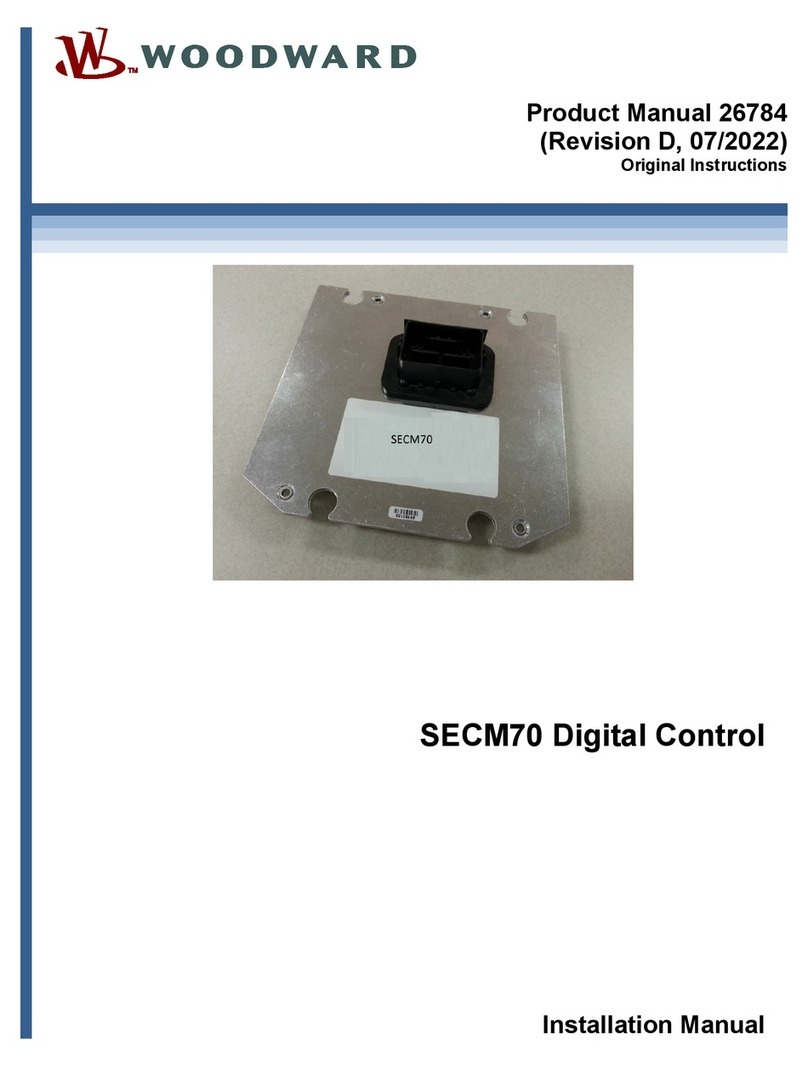
Woodward SECM70 User manual

Woodward

Woodward SECM70 User manual

Woodward MicroNet TMR 5009FT User manual

Woodward

Woodward MicroNet TMR 5009FT User manual

Woodward 2301E-HT User manual

Woodward

Woodward 2301E-HT User manual

Woodward easYgen-1800 User manual

Woodward

Woodward easYgen-1800 User manual

Woodward SPM-D11 User manual

Woodward

Woodward SPM-D11 User manual

Woodward Vertex-Pro User manual

Woodward

Woodward Vertex-Pro User manual

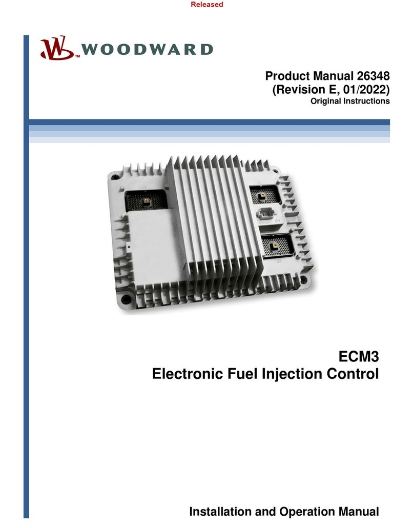
Woodward ECM3 User manual

Woodward

Woodward ECM3 User manual

Woodward easYgen-1700 User manual

Woodward

Woodward easYgen-1700 User manual

Woodward MicroNet TMR 5009 User manual

Woodward

Woodward MicroNet TMR 5009 User manual

Woodward ProAct II Manual

Woodward

Woodward ProAct II Manual

Woodward SG 2D User manual

Woodward

Woodward SG 2D User manual

Woodward 505E Quick start guide

Woodward

Woodward 505E Quick start guide

Woodward SECM112 User manual

Woodward

Woodward SECM112 User manual

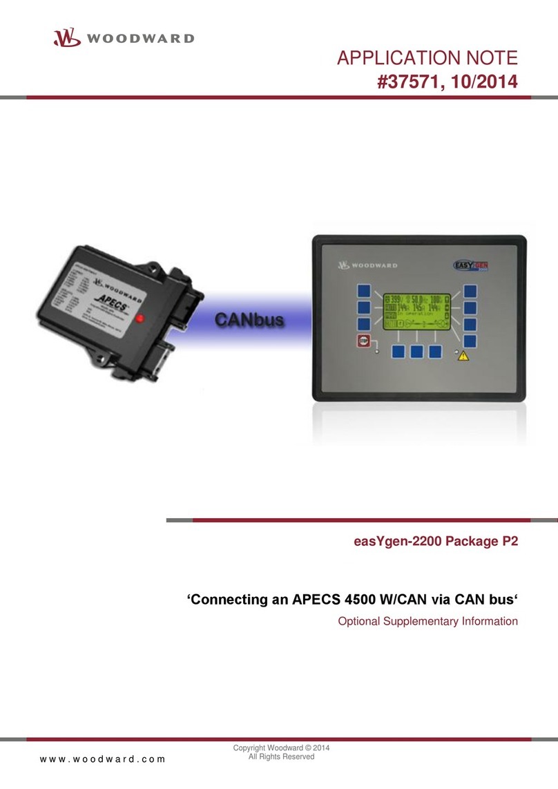
Woodward easYgen-2200 Package P2 Installation and operating instructions

Woodward

Woodward easYgen-2200 Package P2 Installation and operating instructions

Woodward 1907 User manual

Woodward

Woodward 1907 User manual

Woodward MSLC 9907-004 User manual

Woodward

Woodward MSLC 9907-004 User manual

Woodward MicroNet TMR 5009FT User manual

Woodward

Woodward MicroNet TMR 5009FT User manual

Woodward AtlasSC 8273-040 User manual

Woodward

Woodward AtlasSC 8273-040 User manual

Popular Control System manuals by other brands

Balcrank Fusion 3110-027 Service bulletin

Balcrank

Balcrank Fusion 3110-027 Service bulletin

Intermatic PF1102 Installation, operation & service manual

Intermatic

Intermatic PF1102 Installation, operation & service manual

SOMFY inteo CENTRALIS UNO RTS installation guide

SOMFY

SOMFY inteo CENTRALIS UNO RTS installation guide

ETC Emphasis Lighting Control System quick guide

ETC

ETC Emphasis Lighting Control System quick guide

Skip-Line SC-12 Cab Master quick start guide

Skip-Line

Skip-Line SC-12 Cab Master quick start guide

Ruida Technology RDC6432G user manual

Ruida Technology

Ruida Technology RDC6432G user manual

Davin DV-11T II manual

Davin

Davin DV-11T II manual

Prolon C1050 Series Hardware guide

Prolon

Prolon C1050 Series Hardware guide

CDVI BERTA installation manual

CDVI

CDVI BERTA installation manual

HEIDENHAIN POSITIP 880 installation instructions

HEIDENHAIN

HEIDENHAIN POSITIP 880 installation instructions

Altronic DE-3000+ Series operating instructions

Altronic

Altronic DE-3000+ Series operating instructions

Traffic & Access Solutions Portaboom PB2000 user manual

Traffic & Access Solutions

Traffic & Access Solutions Portaboom PB2000 user manual

Knight ILCS Programming manual

Knight

Knight ILCS Programming manual

Philips OccuSwitch Wireless installation guide

Philips

Philips OccuSwitch Wireless installation guide

Varifan VPM-1 user manual

Varifan

Varifan VPM-1 user manual

Bartec APEX (APC) 07-3704 Series operating instructions

Bartec

Bartec APEX (APC) 07-3704 Series operating instructions

Ridder HortiMaX-Go! CloudBoX quick start guide

Ridder

Ridder HortiMaX-Go! CloudBoX quick start guide

Wilo SiFresh Installation and operating instructions

Wilo

Wilo SiFresh Installation and operating instructions

manuals.online logo
manuals.online logoBrands
  • About & Mission
  • Contact us
  • Privacy Policy
  • Terms and Conditions

Copyright 2025 Manuals.Online. All Rights Reserved.