Manual 26839V2 505 Digital Governor for Single/Split-Range Actuators
Woodward 3
Illustrations and Tables
Figure 2-1. DSLC-2 ................................................................................................9
Figure 2-2. Configuration/Woodward Links/DSLC-2............................................10
Figure 2-3. Service Screen - DSLC-2 Power Parameters....................................10
Figure 2-4. Service Screen - DSLC-2 Status Parameters....................................11
Figure 2-5. VS-II...................................................................................................11
Figure 2-6. Configuration/Woodward Links/VS-II.................................................12
Figure 2-7. Service/VariStroke II..........................................................................12
Figure 2-8. Multi-Function Relay ..........................................................................13
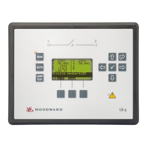
Figure 2-9. LS-5....................................................................................................13
Figure 2-10. Servo Position Controller.................................................................14
Figure 2-11. Interface to Servo Position Controller..............................................14
Figure 2-12. Real Power Sensor..........................................................................15
Figure 2-13. EGCP-3 Control...............................................................................17
Figure 2-14. EGCP-3 LS Functional Diagram......................................................17
Figure 2-15. EGCP-3 LS Interface Wiring............................................................18
Figure 2-16. Typical Redundant I/H System with a Transfer Valve .....................19
Figure 2-17. Typical Redundant I/P System with a Pressure Selecting Relay
Valve................................................................................................20
Figure 3-1. Pump or Compressor Discharge Pressure Control with Turbine Inlet
Pressure Limiting.............................................................................24
Figure 3-2. Inlet Pressure Control with Automatic Synchronizing & Generator
Power Limiting.................................................................................27
Figure 3-3. Exhaust Pressure Control with Generator Power Limiting and Plant
Import/Export Limiting......................................................................31
Figure 3-4. Plant Import/Export Control with DRFD Servo Interface....................36
Figure 3-5. Inlet Pressure Control with Isochronous Loadsharing Control in Island
Mode................................................................................................40
Figure 3-6. Import/Export Control or Exhaust Pressure Control with Isoch Load
Sharing in Island Mode....................................................................43
Figure 4-1 505 Keypad and Display.....................................................................48
Figure 5-1. User Login for Service .......................................................................51
Figure 5-2. Authorized and Unauthorized Components.......................................52
Figure 5-3 Service Menu (page 1)........................................................................53
Figure 5-4 Service Menu (page 2)........................................................................53
Figure 6-1. Proportional Gain Setting Effects.......................................................79
Figure 6-2. Open Loop Proportional and Integral Response ...............................80
Figure 6-3. Closed Loop Proportional and Integral Response.............................81
Figure 6-4. Integral Gain (Reset) Setting Responses ..........................................82
Figure 6-5. Closed Loop Proportional and Derivative Action...............................84
Figure 6-6. Derivative Setting Effects...................................................................84
Figure 6-7. Closed Loop Proportional, Integral and Derivative Action.................85
Figure 6-8. Typical Response to Load Change....................................................87
Figure D-1. SOS.................................................................................................103
Figure D-2. SOS Install Window.........................................................................104
Figure D-3. SOS Server status dialog box.........................................................104
Figure D-4. SOS – New Session box.................................................................105
Figure D-5. SOS - Enter 505 TCP/IP address....................................................105
Figure D-6. SOS – Active Links dialog box........................................................105
Figure E-1. Control Assistant License Agreement .............................................106
Figure E-2. Control Assistant Install Window.....................................................107
Figure E-3. Control Assistant Folder Selection ..................................................107
Figure E-4. Control Assistant Install Complete...................................................107
Figure E-5. Install Restart Window.....................................................................108
Figure E-6. Control Assistant Window................................................................108
