Manual 37105C LS 4 - Circuit Breaker Control
Page 4/92 © Woodward
CHAPTER 5. DISPLAY AND OPERATION COMPONENTS .............................................................. 25
Short Description of LED and Push Buttons ......................................................................................... 25
LEDs............................................................................................................................................ 25
Push Buttons ............................................................................................................................... 25
Miscellaneous.............................................................................................................................. 25
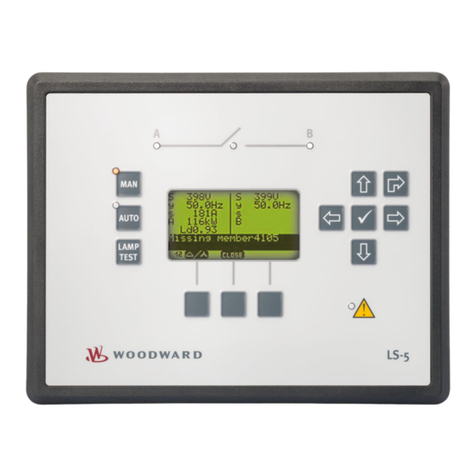
LEDs ...................................................................................................................................................... 26
Push Buttons ......................................................................................................................................... 27
Display ................................................................................................................................................... 28
Automatic Mode (Upper Line of the Display: Measured Values) ................................................ 28
Automatic Mode (Bottom Line of the Display: Measured Values) .............................................. 28
Automatic Mode (Bottom Line of the Display: Alarm Messages)................................................ 29
Interfaces ............................................................................................................................................... 29
Direct Configuration (DPC) ......................................................................................................... 29
CHAPTER 6. CONFIGURATION................................................................................................... 30
Basic Data ............................................................................................................................................. 31
Entering the Configuration..................................................................................................................... 32
Password..................................................................................................................................... 32
Basic Settings ........................................................................................................................................ 33
Direct Configuration..................................................................................................................... 33
Voltage Measuring ...................................................................................................................... 34
Potential Transformer Configuration ........................................................................................... 34
Current Transformer.................................................................................................................... 35
LS 4 Functions....................................................................................................................................... 36
Function....................................................................................................................................... 36
Segment Number ........................................................................................................................ 36
CAN Bus Number (Control Number)........................................................................................... 37
Data Communication via the CAN Bus ....................................................................................... 37
Priority During Breaker Closure .................................................................................................. 37
Preparation.................................................................................................................................. 38
Configuration Screens in the LS 4 .............................................................................................. 38
Configuration Screens in the GCP Control Unit.......................................................................... 41
Examples for Configuration......................................................................................................... 43
Control Functions .................................................................................................................................. 49
Synchronizing Functions ............................................................................................................. 49
Phase Angle Deviation (Phase Shift) .......................................................................................... 51
Blocking of Synchronization at Alarms........................................................................................ 52
Synchronous Networks ............................................................................................................... 53
Dead Bus Start Functions ........................................................................................................... 54
Switching Time Monitoring .......................................................................................................... 55
Monitoring Functions ............................................................................................................................. 56
Monitoring Type Configuration .................................................................................................... 56
Overvoltage Monitoring ............................................................................................................... 57
Undervoltage Monitoring ............................................................................................................. 58
Voltage Asymmetry Monitoring ................................................................................................... 59
Overfrequency Monitoring........................................................................................................... 60
Underfrequency Monitoring......................................................................................................... 61
Phase/Vector Shift Monitoring..................................................................................................... 62
df/dt (ROCOF) Monitoring ........................................................................................................... 63
Relay Configuration ............................................................................................................................... 64
Auto Acknowledgement of the Relays ........................................................................................ 64
Auto Acknowledgement of Messages ......................................................................................... 65
Changing the Relay Assignment................................................................................................. 66
Interface................................................................................................................................................. 69
General Parameters .................................................................................................................... 69
CAN Bus Parameter.................................................................................................................... 70
Change Passwords ............................................................................................................................... 71
