Woodward SPM-D10B/PSY4 User manual

Manual
SPM-D10B/PSY4
- Synchronizing System -
Version 1.1xx
© All Rights reserved. Subject to technical modifications.
Version 37184C
2008/09/Stuttgart
Woodward GmbH
Handwerkstr. 29
70565 Stuttgart - Germany
Tel: +49 (0) 711 78954-0
Fax: +49 (0) 711 78954-100
Website: woodward.com/power

Contents Page
1 INTRODUCTION..................................................................................................................................................3
1.1 Safety technology note for the user.................................................................................................................................3
1.2 Measurement data ..........................................................................................................................................................4
1.2.1 Power supply............................................................................................................................................................4
1.2.2 Voltage measuring inputs.........................................................................................................................................4
1.2.3 Auxiliary and control inputs ......................................................................................................................................5
1.2.4 Auxiliary and control outputs....................................................................................................................................6
2 DESCRIPTION OF FUNCTIONS.........................................................................................................................7
2.1 Function table..................................................................................................................................................................7
2.2 LED "Closed" flashes......................................................................................................................................................7
2.3 Control inputs..................................................................................................................................................................8
2.4 Control outputs................................................................................................................................................................8
2.5 Potential separation between the power supply and the discrete inputs.........................................................................8
2.6 Operating states..............................................................................................................................................................9
2.6.1 No load operation.....................................................................................................................................................9
2.6.2 Synchronization........................................................................................................................................................9
2.6.3 Black Start................................................................................................................................................................9
2.6.4 Isolated operation.....................................................................................................................................................9
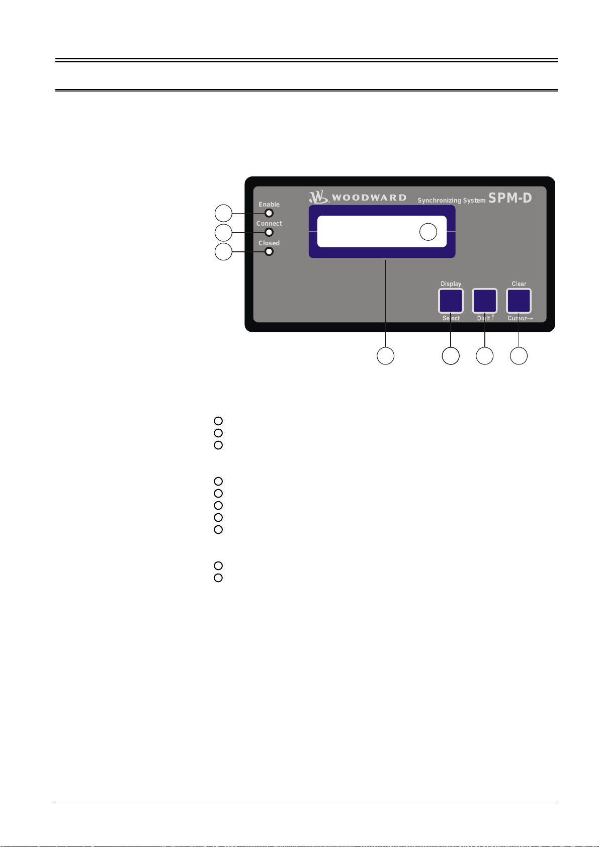
3 DISPLAY ELEMENTS AND CONTROLS .........................................................................................................10
3.1 Pressure-sensitive front membrane...............................................................................................................................10
3.2 Light-emitting diodes.....................................................................................................................................................11
3.3 Buttons..........................................................................................................................................................................12
3.4 Display ..........................................................................................................................................................................13
3.4.1 Automatic mode .....................................................................................................................................................13
3.4.2 Automatic mode Fault display................................................................................................................................13
4 CONFIGURATION SCREENS (INPUT OF THE PARAMETERS)....................................................................14
4.1 Password protection......................................................................................................................................................15
4.2 Basic settings................................................................................................................................................................16
4.3 Controller configuration.................................................................................................................................................17
4.3.1 No-load control.......................................................................................................................................................17
4.3.2 Frequency controller...............................................................................................................................................18
4.3.3 Voltage controller (SPM-D10B/PSY4-FU-D only)...................................................................................................19
4.3.4 Synchronization functions ......................................................................................................................................20
4.3.5 Black start ..............................................................................................................................................................21
4.3.6 Synchronization time monitoring............................................................................................................................21
4.3.7 Change passwords.................................................................................................................................................21
5 COMMISSIONING..............................................................................................................................................22
6 APPENDIX .........................................................................................................................................................24
6.1 Technical data...............................................................................................................................................................24
6.2 Dimensions ...................................................................................................................................................................25
6.3 Wiring diagram..............................................................................................................................................................26
6.3.1 SPM-D10B/PSY4-F-D............................................................................................................................................26
6.3.2 SPM-D10B/PSY4-FU-D .........................................................................................................................................27
7 PARAMETER LIST............................................................................................................................................28
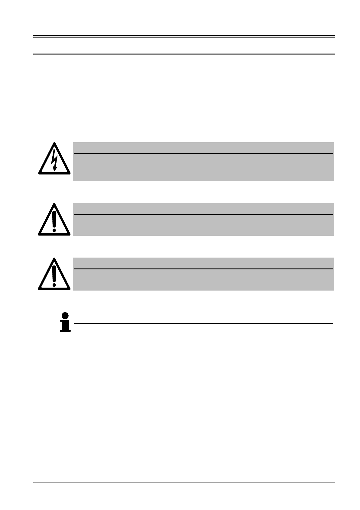
NOTE
This manual has been developed for a unit fitted with all available options. Inputs/outputs, functions,
configuration screens and other details described, which do not exist on your unit may be ignored.
CAUTION !
The present manual has been prepared to enable the installation and commissioning of the device.
On account of the large variety of parameter settings, it is not possible to cover every possible
combination. The manual are therefore only a guide. In case of incorrect entries or a total loss of
functions, the default settings can be taken from the enclosed list of parameters.
SPM-D10B/PSY4 Manual © Woodward
Page 2/28 37184C

1 Introduction
1.1 Safety technology note for the user
This documentation contains the relevant information for the normal use of the pro-
duct described herein. It is intended to be read by qualified staff.
Danger warning The subsequent notes are intended to prevent personal injuries as well as damage to
the described product and any connected units. Safety notes and warnings intended
to prevent any danger to the life and health of users or maintenance personnel and to
avoid any damage will be identified in this documentation by means of the symbols
and terms listed below. Within the framework of this documentation, the signals and
terms that are used have the following meaning:
DANGER !!!
The DANGER symbol draws your attention to dangers while the description indicates how to handle
and/or avoid such hazards. Any non-observance may cause fatal or serious injuries as well as
considerable damage to property.
WARNING !
If the warnings are not observed, the unit and any devices attached to it may be destroyed. Please
take into account appropriate precautions.
CAUTION !
This symbol points to important notes concerning the mounting, installation, and connection of the
unit. These note should absolutely be observed when connecting the unit.
NOTE
References to other notes and supplements as well as tables and lists are identified by means of
the "I" symbol. Most of the referenced sections are included in the Annex.
Proper use The unit must only be operated for the uses described in these manual. The prere-
quisite for a proper and safe operation of the product is correct transportation, sto-
rage, and installation as well as careful operation and maintenance.
© Woodward SPM-D10B/PSY4 Manual
37184C Page 3/28

1.2 Measurement data
WARNING
A circuit breaker must be provided near to the device and in a position easily accessible to the
operator. This must also bear a sign identifying it as an isolating switch for the unit.
NOTE
Connected inductances (e. g. Coils of operating current or undervoltage tripping devices, auxiliary
contactors and power contactors) must be wired with an appropriate interference protection.
1.2.1 Power supply
Power supply
24 V DC (+/-25 %)
24 V DC
0 1
N
2
0 V
Terminal Description Amax
0 Neutral point of the three-phase system or neutral terminal of the
voltage transformer (Measuring reference point);
with three-conductor systems, do not connect Sold.lug
1 Power supply: +24 V DC, 10 W 2.5 mm²
2 Power supply: 0 V reference point 2.5 mm²
1.2.2 Voltage measuring inputs
NOTE
The SPM-D10B/PSY4 can operate (monitor) only one synchronization point. The voltage at
terminals 23/24 (system 1) is the voltage to which the assessment of the synchronization at
terminals 20/21 (system 2) refers. The synchronization voltage can be, e. g., the mains or busbar
voltage.
NOTE
There are generally three different variants for connection of the measuring circuit voltage:
Direct connection to the low voltage system,
Connection to medium voltage via two-pole isolated transformer (e. g. in the case of a
V-connection) and
Connection to medium voltage via single-pole isolated transformer (e. g. Y-connection).
SPM-D10B/PSY4 Manual © Woodward
Page 4/28 37184C

•System 1
L3
GCB
Voltage
System 1
G
L2
L1
23 24
123
N
L1
L2
231
MCB
Note: Connection corresponding to the mains configuration (see connection plan).
Terminal Measurement Description Amax
Connection to the measuring circuit voltage corresponding to variant , or
23 direct
or ../100 V Synchronization voltage L1 2.5 mm²
24 Synchronization voltage L2 2.5 mm²
•System 2
Voltage
system 2
020 21
G
L2
L1
123
MCB
L2
L1
L3
N
GCB
Note: Connection corresponding to the mains configuration (see connection plan).
Terminal Measurement Description Amax
Connection to the measuring circuit voltage corresponding to the variant , or
20 direct or
Transformer
../100 V
Voltage system L1 2.5 mm²
21 Voltage system L2 2.5 mm²
0 Sold.lug
1.2.3 Auxiliary and control inputs
a.) Discrete inputs
•Control inputs
Reply: CB is open
Signal device
CB
Reply Release CB
7 3
18..250 V (AC/DC)
7 4
3
Terminal Accompanying
Zero terminals Name
(according to DIN 40 719 Part 3, 5.8.3) Amax
NO contact
3 7 Enable CB 2.5 mm²
5 Enable isolated operation 2.5 mm²
NC contact
4 7 Reply: CB is open 2.5 mm²
© Woodward SPM-D10B/PSY4 Manual
37184C Page 5/28

1.2.4 Auxiliary and control outputs
a.) Power circuit breakers
Synchronizing impulse:
command: close CB
max. 250 V AC
1415
CB
Root Switched Description Amax
14 15 Synchronizing pulse / Command: close CB 2.5 mm²
b.) Others
max. 250 V AC
AB
external device Relay output
•Alarm relay Normally open contact function
Root Switched Description Amax
A B Note: The relays close when the function is fulfilled.
18 19 Readiness for operation 2.5 mm²
c.) Controller outputs
The controllers are configured as three-point controllers (made of a change-over con-
tact and a normally open contact).
•SPM-D10B/PSY4-F-D Speed/frequency
max. 250 V AC
8 9 10
Speed
governor
Lower
Higher
Common
Frequency controller
•SPM-D10B/PSY4-FU-D
max. 250 Vac
11 12 13
Voltage
controller
Common
Raise
Lower
Voltage controller
8
Common
Speed
controller Speed / frequency
controller
910
Lower
Raise
Terminal Assignment Description Amax
8 common
Speed/frequency controller 2.5 mm²
9 higher 2.5 mm²
10 lower 2.5 mm²
11 common
SPM-D10B/PSY4-FU-D only:
Voltage controller
2.5 mm²
12 higher 2.5 mm²
13 lower 2.5 mm²
SPM-D10B/PSY4 Manual © Woodward
Page 6/28 37184C

2 Description of functions
2.1 Function table
Input signal Function Condition
Discrete input:
"Enable isolated
operation"
LED message on
the front:
"Closed"
LED message on
the front:
"Enable"
x 0 0 No-load operation C
0 0 1
Synchronization of the CB
No-load operation A
C
0 1 x Isolated controller OFF
1 0 1
Synchronization of the CB
Black start of the CB
No-load operation
A
B
C
1 1 x Isolated operation D
0: OFF 1: ON x: Signal of no significance (0 or 1)
Conditions The function of the device is also dependent, apart from the discrete input signals, on
the state of the available measured voltages. The particular function must also be ac-
tivated in configuration mode:
Condition
ASynchronization
CB - for voltages of system 1 and 2 must apply
50 % < V < 125 % of the rated voltage VN
80 % f < 110 % of the rated frequency fN
(after respond of the time monitoring the synchronization will be
interrupted)
BBlack start
CB - Parameter "Black start ON“
- Voltage of system 1 must be smaller than 5 % of the rated vol-
tage.
- Voltage and frequency of system 2 must be within the configured
limits for black start.
CNo-load operation - Parameter "Automatic no load control ON"
- valid for f control:
Voltage system 2 > 50 % rated voltage VN
- SPM-D10B/PSY4-FU-D only - valid for V control:
Frequency system 2 > 90 % of rated frequency fN
DIsolated operation - Voltage system 2 > 50 % rated voltage VN
- SPM-D10B/PSY4-FU-D only - valid for v control:
Param. “Voltage controller in isolated operation ON”
2.2 LED "Closed" flashes
Incorrect signal state of the "Reply: CB is open" on terminal 4.
Possible faults:
- Reply present (= 0 V)
voltages system 1 and system 2 not synchronous
- Reply missing (= 24 V)
voltages system 1 and system 2 synchronous
If the LED is flashing, one must check to see whether the input on terminal 4 is cor-
rectly wired. For the wiring to be correct, there must be a closed power circuit
breaker on the input in question 0 V.
© Woodward SPM-D10B/PSY4 Manual
37184C Page 7/28

2.3 Control inputs
Enable CB
Terminal 3 Release for operation of the power circuit breaker
To enable the synchronization operation or a black start, this input must be set.
Reply: CB is open
Terminal 4 With this input the unit is signaled the status of the power circuit breaker. The input
must be set if the circuit breaker is open. (The status of this input is proved on plau-
sibility and is signaled by LED “Closed”.
Enable isolated operation
Terminal 5 Set.................•Enable frequency/voltage control in the case of missing "Reply:
CB is open" (the LED "Closed" on the front lights up).
•Enable black start for present "Reply: CB is open" (the LED
"Closed" on the front does not light up).
Reset.............•Shut down frequency/voltage controller in the event of a missing
"Reply: CB is open" (the LED "Closed" on the front lights up).
2.4 Control outputs
Command: close CB
Terminals 14/15 By setting this relay the power circuit breaker (CB) will be closed. The relay drops
out after the pulse is output.
Readiness for operation
Terminals 18/19 The relay contact is closed if the unit signals readiness for operation. The relay
drops out if one of the following events occur:
a) The internal self monitoring has indicated a fault. Then a proper working of the
unit can not be guaranteed and from other side appropriate steps must be taken.
b)The synchronization time monitoring is switched on and has responded.
2.5 Potential separation between the power supply and the discrete inputs
By means of an appropriate external wiring, the common reference point of the dis-
crete inputs (terminal 7) can be electrically isolated from the supply voltage (0 V, ter-
minal 2). This is necessary, for example, if the discrete inputs are not to be driven
with +24 Vdc and an electrical isolation of the control voltage (e. g. 220 Vdc,
220 Vac) must be guarantee for the power supply.
Wiring should be made as follows:
•Reference points connected with 0 V:
Bridge between terminal 7 and terminal 2 (0 V)
•Reference point of the discrete inputs potential-free:
Terminal 2: 0 V (Power supply)
Terminal 7: 0 V or N (control voltage)
SPM-D10B/PSY4 Manual © Woodward
Page 8/28 37184C

2.6 Operating states
2.6.1 No load operation
The frequency and the voltage (SPM-D10B/PSY4-FU-D only) of system 2 are con-
trolled to the configured setpoint value by operating accordingly the relays of the
three-position controller for speed and voltage (SPM-D10B/PSY4-FU-D only; see al-
so chapter 2.1 "Function table" on page 7). The circuit breaker is open.
2.6.2 Synchronization
The voltage of system 2 is controlled to the voltage of system 1 in its frequency and
amplitude (SPM-D10B/PSY4-FU-D only) by operating accordingly the relays of the
three-position controller for speed and voltage (SPM-D10B/PSY4-FU-D only). With
consideration of the switcher time element the add-on command for the circuit break-
er is output in the synchronous point. The synchronization occurs under the following
conditions (see also chapter 2.1 „Function table“ on page 7):
•The unit is in automatic mode,
•the synchronous function is set,
•the frequency and the voltage (SPM-D10B/PSY4-FU-D only) are within the prede-
termined limits (see also chapter 2.1 “Function table” on page 7),
•the input "Enable CB" is set and
•the input "Reply: CB is open" is set,
•the synchronization time monitoring is not set or has not responded.
2.6.3 Black Start
Output of a add-on command for the circuit breaker without synchronization, if the fol-
lowing conditions are fulfilled:
•The unit is in automatic mode;
•the parameter "black start" has been set to "ON",
•the voltage of system 1 is not available (USystem1 < 5 % UN),
•the voltage and frequency of system 2 are within the configured limits,
•the input "Isolated operation" is set,
•the input "Enable CB" is set and
•the input "Reply: CB is open" is set.
2.6.4 Isolated operation
The frequency and the voltage (SPM-D10B/PSY4-FU-D only) of system 2 are con-
trolled on the configured set value by operating accordingly the relays of the three-
position controller for speed and voltage (SPM-D10B/PSY4-FU-D only;see also
chapter 2.1 "Function table" on page 7). The circuit breaker is open. To activate the
voltage controller the parameter "Voltage controller in isolated operation" has to be
configured to ON (SPM-D10B/PSY4-FU-D only).
© Woodward SPM-D10B/PSY4 Manual
37184C Page 9/28

3 Display elements and controls
3.1 Pressure-sensitive front membrane
The pressure-sensitive membrane of the front panel consists of a plastic coating. All
keys have been designed as touch-sensitive membrane switch elements. The display
is an LC display, comprising 2 × 16 characters, which are indirectly illuminated in
green. Contrast of the display is infinitely variable by a rotary potentiometer at the left
side.
Thomas
Closed
Connect
Enable
Digit Cursor
Reset
Display
Enter
Closed
Enable
Connect
Synchronizing System
SPM-D
15
1
2
3
12 13 14124
_________________________________________________ Light-emitting diodes
1"Enable"...................................................................................................Enable CB
2"Connect"...................................................................................... Connection pulse
3"Closed".....................................................................................Reply: CB is closed
_____________________________________________________________Buttons
12 "Display" ..............................................................................................Scroll display
12 "Select"......................................................................................... Confirm selection
13 "Digit“...................................................................................................Increase digit
14 "Clear"......................................................................................Acknowledge alarms
14 "Cursor" ............................................................................Input cursor 1 to the right
_____________________________________________________________ Display
4"Synchronism" ............................................................Synchronism system 1 and 2
15 "LC display" .............................................................................................LC display
SPM-D10B/PSY4 Manual © Woodward
Page 10/28 37184C

3.2 Light-emitting diodes
1.........................................LED
" Enable" Enable circuit breaker Color "GREEN"
The light emitting diode "Enable" indicates that the circuit breaker is enabled for op-
eration. The status of the LED corresponds with the status of the discrete input “En-
able CB”.
2.........................................LED
" Connect " Connection pulse Color "GREEN"
The light-emitting diode “Connect" indicates that the unit gives a add-on pulse to the
circuit breaker. The condition of the LED corresponds with the condition of the relay
“Command: close CB”.
3.........................................LED
"Closed" Circuit breaker is closed Color "GREEN"
The LED “Closed” signals the reply of the circuit breaker. The LED is illuminated if
the discrete input “Reply: CB is open” is not set and it expires if the discrete input is
set (see also chapter 2.2 “LED "Closed" flashes” on page 7).
© Woodward SPM-D10B/PSY4 Manual
37184C Page 11/28

3.3 Buttons
In order to facilitate the setting of the parameters, the buttons have an "AUTOROLL
function". It allows to switch to the next setting and configuration screens, the digits,
or the cursor position. The "AUTOROLL function" will only be activated when the user
depresses the corresponding keys for a certain period of time.
12 .................................BUTTON
"Display..Select" Display↓..Select
Automatic.................. "Display" Pressing this button advances the display of the
operating and alarm messages.
Configuration............ "Select" The jump to the next input screen occurs. If the orig-
inally displayed value has been changed by the buttons
"Digit" or "Cursor", then the newly set value is saved by
pressing the "Select" button. By pressing this button
again, the user causes the system to display the next en-
try screen.
13 .................................BUTTON
"Digit
↑
" Digit ↑
Configuration............ "Digit↑" This button is used to raise the cursor position one
digit from where the cursor is. The increase is restricted
by the admissible limits see list of parameters included in
the Annex. In case the maximum number is reached
which can be set, the number automatically returns to the
lowest admissible number.
14 .................................BUTTON
"Clear..Cursor" Clear..Cursor
Automatic.................. "Clear" By pressing this button all fault messages are deleted
if they are no longer detected.
Configuration............ "Cursor→" This button is used to move the cursor one posi-
tion to the right. When the last right-hand position is
reached, the cursor automatically moves to the first posi-
tion left-hand of the value to be entered.
SPM-D10B/PSY4 Manual © Woodward
Page 12/28 37184C

3.4 Display
15 ................................ DISPLAY
"LC display"
“Synchronism”
LC display
The two-line LC display may be used to retrieve performance quantities when the
automatic mode is activated. While in configuration mode, the individual parameters
are indicated (see below).
3.4.1 Automatic mode
1:00,0kV 00,00Hz
2:00,0kV 00,00Hz
Double voltage and double frequency display, phase position
The voltages of both systems 1 and 2 are displayed. The arbor in the lower line
shows the phase position between system 1 and system 2. Are both systems syn-
chronous the arbor is positioned above the indentation of the display frame. The ar-
bor would only be displayed during system 1 and system 2 are both within the ad-
missible range for the synchronization (see chapter 2.1, condition A).
1................Voltage and frequency of system 1
2................Voltage and frequency of system 2
d±000%R±00,00HzR
-------█-------
Voltage and frequency difference, phase position
The difference voltages and difference frequencies between both systems 1 and 2
are displayed. A positive difference means that system 2 has a larger value than
system 1. The voltage difference shown in % is related to the voltage transformer
rated value of system 2. Right hand to the % sign a blinking arrow shows the activity
of the voltage controller (SPM-D10B/PSY4-FU-D only), right hand to the unit "Hz"
the activity of the frequency controller is displayed. If the point of the arrow shows to
the top the controller outputs "higher" impulses; if the point of the arrows shows to
the bottom the controller outputs "lower" impulses. The frequency of the blinking ar-
rows do not represent the controller outputs frequency. The sign in the lower line
shows the phase position between system 1 and system 2. Are both systems syn-
chronous the sign is sitting above the indentation of the display frame. All above de-
scribed values would only be displayed during system 1 and system 2 are both with-
in the admissible range for the synchronization (see chapter 2.1, condition A).
3.4.2 Automatic mode Fault display
xxxxxxxxxxxxxxxx
Fault display, lower line
The indications are displayed according to the following list:
Type of fault xxxxxxxxxxxxxxxx
Synchronization time of the CB is exceeded Synchron. time
© Woodward SPM-D10B/PSY4 Manual
37184C Page 13/28

4 Configuration screens (input of the parameters)
The input screens can be scrolled, when you are in configuration mode (simulta-
neously pressing "Digit" and "Cursor"), via "Select". If the "Select" button is pressed
for a longer period of time, the scroll function will be activated, and the screens will
be browsed rapidly. Please make sure that it is possible to scroll in the reverse direc-
tion of the last four configuration screens. To do this you must simultaneously press
the buttons "Select" and "Cursor". If no entry, modification or any other action is car-
ried out for about 10 minutes, the unit automatically returns to the automatic mode.
SPRACHE/LANGUAGE
english
Language selection German/English
Selection of the language.
- -
Software version
x.xxxx
Software version
Display of the software version.
SPM-D10B/PSY4 Manual © Woodward
Page 14/28 37184C

4.1 Password protection
The unit is equipped with a three-level code and configuration hierarchy, which
enables it to visualize various configuration screens for different users. A distinction
is made between:
Code level 0 User: Third party
(CS0) This code level enables no access whatsoever to the parameters.
Code level 1 User: Customer
(CS1) This code level entitles the user to change a few selected parameters. Changing a
password is not possible in this case.
Code level 2 User: Commissioner
(CS2) With code level 2 the user acquires all access rights, and therefore has direct access
to all parameters (displaying and changing). In addition, the user may also set the
password for levels 1 and 2 in this level.
Enter code
number XXXX
Enter code number 0..9999
On accessing the configuration mode, a code number, which identifies the various
users, is first requested. The displayed number XXXX is a random number (RN). If
the random number is confirmed by “Select” without changing the item’s code level
remains as it was. If the code number of level 1 or level 2 is input, the unit changes
into code level CS1 or CS 2 and accordingly the parameter can be changed. If an
incorrect code number is input, the code level is set to code level 0.
NOTE
Two hours after input of the code number the code level returns automatically to CS0!
The present code number for code level 1 (CS1) is "0001" !
The present code number for code level 2 (CS2) is "0002" !
Only in code level 2 the pass word protection can be switched off!
Password
Protection ON
Password protection ON/OFF
ON............Access to configuration is attained by entering the appropriate password
(Code level 0/1/2). If an incorrect code number has been entered, confi-
guration is blocked.
OFF ..........Access to configuration screens is permanently set to code level 2 and
the code number is not queried.
© Woodward SPM-D10B/PSY4 Manual
37184C Page 15/28

4.2 Basic settings
WARNING !
Incorrect entries may lead to wrong measured results and cause the destruction of the generator!
Rated frequency
fn=00.0Hz
System rated frequency 48.0..62.0 Hz
The rated frequency of the systems 1 and 2 (respectively of the public network) is
transferred here to the unit. This parameter depends on the three-phase system in
the relevant country.
Generator freq.
f set = 00.0Hz
Setpoint frequency 48.0..62.0 Hz
The setpoint frequency of system 2 is entered in this screen and is needed for the
frequency controller in isolated and no-load operation.
Voltage System 1
secondary 000V
Secondary voltage system 1 (measuring transducer) 50..440 V
The secondary voltage of system 1 is set here in V. This entry serves to indicate the
primary voltages in the display. In the case of measured voltages of 400 V without a
measurement transducer, 400 V must be set here.
Voltage System 2
secondary 000V
Secondary voltage of system 2 (measuring transducer) 50..440 V
Secondary voltage of system 2 is set here in V. This entry serves to indicate the pri-
mary voltages in the display. In the case of measured voltages of 400 V without a
measurement transducer, 400 V must be set here.
Voltage System 1
primary 00.000kV
Primary voltage of system 1 (measuring transducer) 0.1..65.0 kV
The primary voltage of system 1 is set here in kV. The entry is used to output the
primary voltages on the display. In the case of measured voltages of 400 V without a
measurement transducer, 0.40 kV must be set here.
Voltage System 2
primary 00.000kV
Primary voltage of system 2 (measuring transducer) 0.1..65.0 kV
The primary voltage of system 2 is set her in kV. The entry is used to output the pri-
mary voltages on the display. In the case of measured voltages of 400 V without a
measurement transducer 0.40 kV must be set here.
Rated voltage
Un = 000V
Rated voltage 70..420 V
This value is used to define the permitted limits for synchronization.
Voltage System 2
setpoint 000V
SPM-D10B/PSY4-FU-D only
Setpoint voltage system 2 50..440 V
This value of the voltage specifies the setpoint of the voltage of system 2 for no-load
and isolated operation.
SPM-D10B/PSY4 Manual © Woodward
Page 16/28 37184C

4.3 Controller configuration
The parameters of the controller are modified by entering values in the following
screens.
WARNING !
An incorrect input can lead to uncontrolled controller actions and destroy the generator!
4.3.1 No-load control
Automatic idle
Running ON
Automatic no-load control ON/OFF
ON............With the circuit breaker open and no release of the circuit breaker, fre-
quency and if applicable voltage are controlled (see also chapter 2.1
“Function table” on page 7).
OFF ..........With the circuit breaker open, frequency and if applicable voltage are
controlled according to the following conditions (see also chapter 2.1
“Function table” on page 7):
•CB release is present:
Frequency and if applicable voltage are controlled.
•Release CB is not present:
No control is carried out.
© Woodward SPM-D10B/PSY4 Manual
37184C Page 17/28

4.3.2 Frequency controller
Freq. controller
ON
Frequency controller ON/OFF
ON............The frequency of system 2 is controlled. The frequency is controlled in
various manners depending on the task (isolated operation / synchroni-
zation). The subsequent screens of this option are displayed.
OFF ..........Control is not carried out, and the subsequent screens of this option are
not displayed.
Freq.controller
Ramp 00,0Hz/s
Frequency controller setpoint ramp 0,1..99,9 Hz/s
The change in setpoint is supplied to the controller via a ramp. The slope of the
ramp is used to alter the rate at which the controller modifies the setpoint value. The
more rapidly the change in the setpoint is to be carried out, the greater the value in-
put here must be.
Freq. controller
Dead band=0.00Hz
Frequency controller insensitivity 0.02..1.00 Hz
Isolated operationThe setpoint frequency of system 2 is controlled in such a man-
ner that, in its adjusted state, the actual value deviates from the
setpoint frequency setting (setpoint from mask setting) by the set
sensitivity value at most.
Synchronization...The frequency of system 2 is controlled in such a manner that, in
its adjusted state, the differential frequency reaches the set sen-
sitivity value at most. The frequency of system 1 is used as the
setpoint value increased by the value of the adjustable offset.
Freq. controller
Time pulse>000ms
Minimum frequency controller ON period 10..250 ms
The minimum ON period of the relay should be selected in such a manner that the
downstream adjustment facility responds reliably to the pulse that has been set ac-
cording to the set time. The smallest possible time must be set in order to ensure op-
timum control behavior.
Freq. controller
Gain Kp = 00.00
Frequency controller gain 0.1..99.9
The gain factor Kpinfluences the operating time of the relays. By increasing the fac-
tor, the operating time can be increased in the event of a certain control deviation.
SPM-D10B/PSY4 Manual © Woodward
Page 18/28 37184C

4.3.3 Voltage controller (SPM-D10B/PSY4-FU-D only)
Volt. controller
ON
Voltage controller ON/OFF
ON............Generator voltage control is carried out. The generator voltage is con-
trolled in various manners depending on the task (no load / isolated op-
eration / synchronization). The subsequent screens of this option are
displayed.
OFF ..........Control is not carried out, and the subsequent screens of this option are
not displayed.
Volt. controller
Isolated op. ON
Voltage controller isolated mode ON/OFF
ON............In the operation mode isolated operation the voltage controller is acti-
vated.
OFF ..........In the operation mode isolated operation the voltage controller is inac-
tive. The frequency controller is not affected by this setting.
Volt. controller
dead band= 00.0%
Voltage controller insensitivity 0.1..25.0 %
The dead band given in % is related to the voltage transformer rated value of the
voltage system 2.
No load/Isolated operation The voltage is controlled in such a manner that, in its
adjusted state, the actual value deviates from the setpoint vol-
tage setting (setpoint from mask setting) by the set sensitivity
value at most.
Synchronization...The generator voltage is controlled in such a manner that, in its
adjusted state, the differential voltage reaches the set sensitivity
value at most. The mains or busbar voltage is used as the set-
point value.
Volt. controller
time pulse>000ms
Minimum voltage controller ON period 20..250 ms
The minimum ON period of the relay should be selected in such a manner that the
downstream adjustment facility responds reliably to the pulse that has been set ac-
cording to the set time. The smallest possible time must be set in order to ensure op-
timum control behavior.
Volt. controller
gain Kp=00.0
Voltage controller gain factor 0.1..99.9
The gain factor Kpinfluences the operating time of the relays. By increasing the fac-
tor, the operating time can be increased in the event of a certain control deviation.
© Woodward SPM-D10B/PSY4 Manual
37184C Page 19/28

4.3.4 Synchronization functions
Synchronizing
functions ON
Synchronization functions ON/OFF
ON............A synchronization of the frequency of system 1 is carried out. The add-
on command for the CB is carried out with little positive slip. The subse-
quent screens of this function are displayed.
OFF ..........No synchronization occurs, and the subsequent screens of this function
are not displayed.
Synchronizing
df offs.= 0,00Hz
Offset frequency 0.00..0.25 Hz
During synchronization the setpoint value of the frequency of the system 2 is calcu-
lated out of the frequency of system 1 added by this offset. This offset should be at
least 0.1 Hz smaller or half the value of dfmax (next parameter). Please also note
the setting of the insensitivity of the controller, too.
Synchronization
df max = 0.00Hz
Max. perm. differential frequency for synchron. (pos. slip) 0.02..0.49 Hz
The prerequisite of a connect command's being output is negative deviation from
this set differential frequency. This value specifies the upper frequency (positive val-
ue corresponds to positive slip).
frequency of system 2 is larger than frequency of system 1.
Synchronization
df min = 0.00Hz
Max. perm. differential frequency for synchron. (neg. slip) 0.00..-0.49 Hz
The prerequisite of a connect command's being output is negative deviation from
this set differential frequency. This value specifies the lower frequency (negative
value corresponds to negative slip).
frequency of system 2 is smaller than frequency of system 1.
Synchronization
dU max = 00.0%
Max. perm. differential voltage for synchronization 0.1..15.0 %
The dead band given in % is related to the voltage transformer rated value of the
voltage system 2.
To ensure that a connect command will be issued, the actual value must fall below
the entered differential voltage.
Synchronization
Time pulse>0.00s
Min. pulse duration of connect relay for synchronization 0.04..0.50 s
The duration of the connect impulse can be adjusted to the subordinate switching
unit.
Closing time
CB =000ms
Inherent delay of the CB for synchronization 40..300 ms
The inherent switching time of the circuit breaker corresponds to the lead time of the
connect command. The connect command will be issued at the entered time before
the synchronization point.
SPM-D10B/PSY4 Manual © Woodward
Page 20/28 37184C
This manual suits for next models
2
Table of contents
Other Woodward Recording Equipment manuals
Popular Recording Equipment manuals by other brands

Philips
Philips CDR 785 manual

Sound Devices
Sound Devices Kashmir MIXPRE-3 II quick start guide

Behringer
Behringer 2600-VCO quick start guide

PASCO
PASCO 850 Universal Interface instruction manual

Altinex
Altinex System Interface Audio & Equalization VA6822 user guide

MDT Technologies
MDT Technologies BE-04001.01 Technical instructions