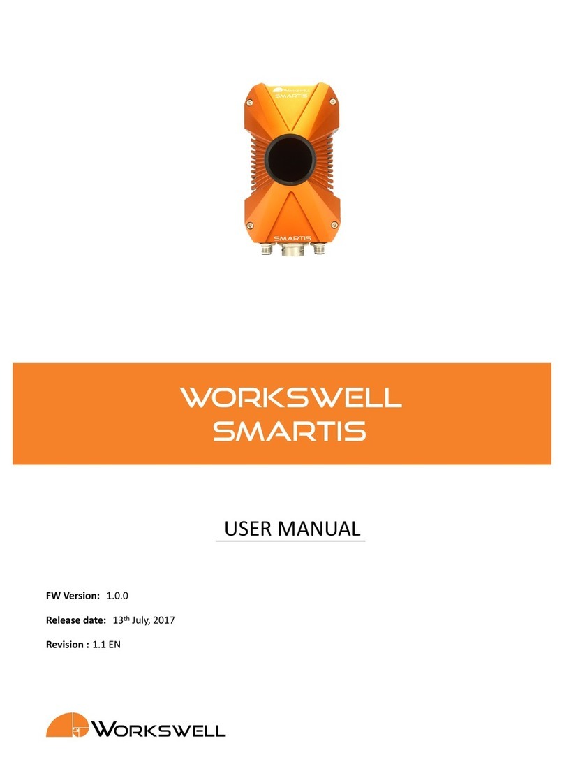
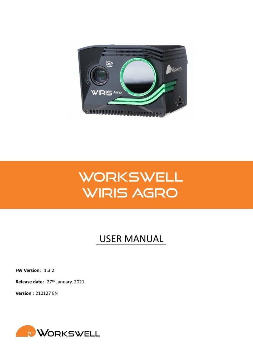
WORKSWELL SMARTIS User manual

WORKSWELL
SMARTIS
USER MANUAL
FW Version: 1.0.0
Release date: 27th January, 2021
Version : 210127 EN

Contents
1. Introducon 4
1.1 LegalDisclaimer........................................... 4
1.2 Copyright .............................................. 4
2. Help and FAQ 5
2.1 GeneralInstrucons......................................... 5
3. User Informaon 6
3.1 TypographicConvenons...................................... 6
3.2 HelpandCommunityForum .................................... 6
3.3 Updates............................................... 6
3.4 Firmware .............................................. 6
4. Warning and Cauons 7
4.1 Warnings .............................................. 7
4.2 Nocaons............................................. 7
5. Revision History 8
6. System assembly 9
6.1 Connecon ............................................. 9
6.1.1 PowerSupply........................................ 9
6.1.2 DigitalTriggers ....................................... 9
6.1.3 DigitalOutputs ....................................... 10
6.1.4 AnalogOutputs....................................... 11
6.2 Mounngthesystem ........................................ 12
7. General usage overview 13
7.1 ControllingSMARTIS ........................................ 13
7.1.1 Webserver ......................................... 13
7.1.2 Logincontrol ........................................ 13
7.1.3 Users ............................................ 13
7.1.4 Admin and Operator Modes . . . . . . . . . . . . . . . . . . . . . . . . . . . . . . . . 14
7.2 Productsoverview ......................................... 14
7.2.1 MeasurementModes.................................... 14
7.2.2 ROI ............................................. 14
7.3 Measurementoverview....................................... 15
7.3.1 Measurementsession ................................... 15
7.3.2 Digital and analog inputs and outputs . . . . . . . . . . . . . . . . . . . . . . . . . . . 15
8. Login 16
8.1 Nomeasurementinprogress.................................... 16
8.2 Measurementinprogress...................................... 17
9. Administrator Mode 18
1

9.1 System................................................ 18
9.1.1 BasicSengs........................................ 18
9.1.2 NetworkSengs...................................... 19
9.1.3 TimeandDateSengs................................... 20
9.1.4 UserSengs ........................................ 20
9.1.5 LogFilesSengs ...................................... 21
9.2 Products............................................... 22
9.3 Radiometry ............................................. 23
9.4 Modes................................................ 23
9.4.1 Frame Measurement and Evaluaon . . . . . . . . . . . . . . . . . . . . . . . . . . . . 24
9.4.2 Start‐Stop Measurement and Evaluaon . . . . . . . . . . . . . . . . . . . . . . . . . . 25
9.4.3 ConnuousEvaluaon ................................... 25
9.4.4 Non‐TriggerEvaluaon................................... 26
9.5 ROI.................................................. 27
9.5.1 ROIshapes ......................................... 27
9.5.2 Zoom ............................................ 28
9.5.3 RangeandPalee ..................................... 28
9.5.4 Sengspanel........................................ 29
9.5.5 EditROIpanel........................................ 29
9.5.6 Sequencepanel....................................... 29
9.6 Table................................................. 31
9.6.1 Stasc ........................................... 31
9.6.2 Value ............................................ 31
9.6.3 Extreme........................................... 31
9.6.4 Operator .......................................... 31
9.6.5 Extremeval.......................................... 31
9.6.6 Digital............................................ 32
9.6.7 Analog ........................................... 32
9.6.8 CopyingROIsengs .................................... 32
9.7 Outputs ............................................... 33
9.7.1 AnalogOutputs....................................... 33
9.7.2 DigitalOutputs ....................................... 34
9.8 Visualizaon............................................. 35
9.9 Finish ................................................ 36
10. Operator Mode 37
10.1Graphicalinterface ......................................... 37
10.1.1 Individualparts....................................... 37
10.1.2 Measurement types dierences . . . . . . . . . . . . . . . . . . . . . . . . . . . . . . 40
10.2Work‐ow.............................................. 42
10.3Measurementsession........................................ 42
10.3.1 Web server during measurement session . . . . . . . . . . . . . . . . . . . . . . . . . 42
10.3.2 Power cut during measurement session . . . . . . . . . . . . . . . . . . . . . . . . . . 42
11. Ethernet 43
11.1CommunicaonProtocol ...................................... 43
2
12. Data Transfer 46
12.1FTPServer.............................................. 46
12.1.1 Restricons and warnings . . . . . . . . . . . . . . . . . . . . . . . . . . . . . . . . . 46
12.1.2 Soware for accessing FTP . . . . . . . . . . . . . . . . . . . . . . . . . . . . . . . . . 47
13. Firmware update 48
13.1Firmwareupdate .......................................... 48
14. Workswell CorePlayer 49
14.1GeneralDescripon......................................... 49
15. Environment Condions 50
15.1EnvironmentCondions ...................................... 50
16. Infrared camera behaviour 51
16.1Infraredcamerawarm‐up...................................... 51
16.2Non‐uniformitycorrecon ..................................... 51
17. Maintanance 52
17.1 Cleaning the SMARTIS head and cables . . . . . . . . . . . . . . . . . . . . . . . . . . . . . . . 52
17.2Cleaningtheinfraredlens...................................... 52
18. Troubleshoot 53
18.1TurningON ............................................. 53
18.2Conneconerror .......................................... 53
18.3FactoryDefault ........................................... 53
18.4LEDstatus.............................................. 53
18.5SystemUpdate ........................................... 54
E‐mail and Web
info@workswell.eu
www.workswell.eu
Mobile:
+420 725 877 063
ID:
Reg. No.: 29048575
VAT No.: CZ29048575
Headquarters
Libocka 653/51b
Prague, Czech Republic
Version 210127 EN, 27th Jan, 2021
All pictures are only for illustraon.
Real values may vary.
3

1. INTRODUCTION
1 Introducon
1.1 Legal Disclaimer
All products (soware, hardware or rmware) manufactured by Workswell s.r.o. are warranted against defecve
materials and workmanship for a period of twelve (12) months, provided such products have been under normal
storage and use in accordance with herein instrucons.
The warranty extends only to the original purchaser and is not transferable. It is not applicable to any product
which has been subjected to misuse, neglect, accident or abnormal condions of operaon.
In the case of a defect in a product covered by this warranty the product must not be further used in order to
prevent addional damage. The purchaser shall promptly report any defect to Workswell s.r.o. or its authorized
distributor or this warranty will not apply.
Workswell s.r.o. will, at its opon, repair or replace any such defecve product free of charge if, upon inspecon,
it proves to be defecve in material or workmanship and provided that it is returned to Workswell within the
said twelve‐month period.
Nobody but Workswell s.r.o. is allowed to open or modify such product.
Workswell s.r.o. has no other obligaon or liability for defects than those set forth above. No other warranty is
expressed or implied. Workswell s.r.o. shall not be liable for any direct, indirect, special, incidental or consequenal
loss or damage, whether based on contract, tort or any other legal theory.
1.2 Copyright
© Workswell s.r.o. All rights reserved worldwide. No parts of the soware including source code may be
reproduced, transmied, transcribed or translated into any language or computer language in any form or by any
means, electronic, magnec, opcal, manual or otherwise, without the prior wrien permission of Workswell
s.r.o.
Names and marks appearing on the products herein are either registered trademarks or trademarks of Workswell
s.r.o. All other trademarks, trade names or company names referenced herein are used for idencaon only
and are the property of their respecve owners.
E‐mail and Web
info@workswell.eu
www.workswell.eu
Mobile:
+420 725 877 063
ID:
Reg. No.: 29048575
VAT No.: CZ29048575
Headquarters
Libocka 653/51b
Prague, Czech Republic
Version 210127 EN, 27th Jan, 2021
All pictures are only for illustraon.
Real values may vary.
4

2. HELP AND FAQ
2 Help and FAQ
2.1 General Instrucons
While looking for a soluon of any technical problem we recommend following these steps:
try to nd an answer by searching this User Manual
contact your dealer
search Workswell s.r.o. website at hps://workswell.cz/termokamera‐smars/
log in and send an email to support.workswell.eu
E‐mail and Web
info@workswell.eu
www.workswell.eu
Mobile:
+420 725 877 063
ID:
Reg. No.: 29048575
VAT No.: CZ29048575
Headquarters
Libocka 653/51b
Prague, Czech Republic
Version 210127 EN, 27th Jan, 2021
All pictures are only for illustraon.
Real values may vary.
5

3. USER INFORMATION
3 User Informaon
3.1 Typographic Convenons
Following typographic convenons are used in this User Manual:
UPPER CASE is used for the names of keys, buons and menu items
COURIER is used for lenames and paths
Italic is used for important informaon and document names
bold is used for the links to other secons, for funcon names or internet sites
3.2 Help and Community Forum
For technical quesons that were not answered in this User Manual feel free to contact your dealer or visit
the product website at hps://workswell.cz/termokamera‐smars/. Try to nd an answer by searching the
Community Forum and if there is not such answer please log in and send an email on support.workswell.eu.
3.3 Updates
The primary aim of Workswell s.r.o. company is to supply their products in a way to meet the current needs of
its users and at the same me to remove all the weaknesses that were found in their use as soon as possible.
For this reason, Workswell s.r.o. regularly releases updates for all their products.
3.4 Firmware
Firmware is the „internal“ control program of the device. From the user’s point of view, only the ocial rmware
released by Workswell s.r.o. company can be used for update of the device.
E‐mail and Web
info@workswell.eu
www.workswell.eu
Mobile:
+420 725 877 063
ID:
Reg. No.: 29048575
VAT No.: CZ29048575
Headquarters
Libocka 653/51b
Prague, Czech Republic
Version 210127 EN, 27th Jan, 2021
All pictures are only for illustraon.
Real values may vary.
6

4. WARNING AND CAUTIONS
4 Warning and Cauons
4.1 Warnings
Before using the product, please check that there is no visible damage or malfuncon. If there are any visible
signs of damage or other defect on the device, then on no account should it be installed or put into operaon.
Any interference and non‐cered service operaons into the product leads to an automac loss of warranty.
4.2 Nocaons
Do not use or store the device in conict with the storage and operang condions laid down in this manual
(only for hardware).
Do not point the infrared camera (with or without the lens cover) at strong energy sources, for example,
devices that cause laser radiaon, or the sun. This can have an unwanted eect on the accuracy of the
camera. It can also cause damage to the detector in the camera.
Plug the camera to its own power source. Do not plug the camera into the same power source as drone’s
motors.
Do not use the Workswell SMARTIS system in temperatures higher than +50◦C (+122◦F). High temperatures
can cause damage to the camera.
Do not use the Workswell SMARTIS system in temperatures lower than ‐15◦C (+5◦F). Low temperatures
can cause damage to the camera.
Do not apply solvents or equivalent liquids to the cameras, the cables, or other items. Damage to the items
can occur.
Be careful when you clean the infrared lens. The lens has an an‐reecve coang which is easily damaged.
Do not use too much force to clean the infrared lens. This can cause damage to the an‐reecve coang.
The encapsulaon rang is only applicable when all the openings on the all components of the system are
sealed with their correct covers, hatches, or caps.
E‐mail and Web
info@workswell.eu
www.workswell.eu
Mobile:
+420 725 877 063
ID:
Reg. No.: 29048575
VAT No.: CZ29048575
Headquarters
Libocka 653/51b
Prague, Czech Republic
Version 210127 EN, 27th Jan, 2021
All pictures are only for illustraon.
Real values may vary.
7

5. REVISION HISTORY
5 Revision History
1.0.0
Inial Release
210127
Added new support contact and version numbering.
E‐mail and Web
info@workswell.eu
www.workswell.eu
Mobile:
+420 725 877 063
ID:
Reg. No.: 29048575
VAT No.: CZ29048575
Headquarters
Libocka 653/51b
Prague, Czech Republic
Version 210127 EN, 27th Jan, 2021
All pictures are only for illustraon.
Real values may vary.
8

6. SYSTEM ASSEMBLY
6 System assembly
6.1 Connecon
For fully controlling the SMARTIS you need:
Ethernet Cable
1x M12 5‐pin cable for power supply
3x M12 8‐pin cables for Digital Triggers, Digital Outputs and Analog Outputs
6.1.1 Power Supply
You can power your SMARTIS with M12 5‐pin cable. Voltage between VCC and GND pins must be within range
18VDC ‐ 32VDC. You can see the power connector pinout in the Figure 6.1a.
(a) Power supply connector
pinout.
Contact Funcon Color
1 VCC+ Brown
2 VCC+ White
3 GND Black
4 GND Blue
5 NC Gray
(b) Power supply wire coloring.
Note: Exceeding the input power range may cause damage to the SMARTIS.
6.1.2 Digital Triggers
You can trigger your SMARTIS with M12 8‐pin cable. Trigger level of each trigger is within range 8VDC ‐ 36VDC.
You can see the trigger connector pinout in the Figure 6.2a.
E‐mail and Web
info@workswell.eu
www.workswell.eu
Mobile:
+420 725 877 063
ID:
Reg. No.: 29048575
VAT No.: CZ29048575
Headquarters
Libocka 653/51b
Prague, Czech Republic
Version 210127 EN, 27th Jan, 2021
All pictures are only for illustraon.
Real values may vary.
9

6. SYSTEM ASSEMBLY
(a) Connector pinout.
Contact Funcon Color
1 LATCH+ White
2 GND_T Brown
3 START+ Green
4 GND_T Yellow
5 STOP+ Gray
6 GND_T Pink
7 NUC+ Blue
8 GND_T Red
(b) Digital triggers wire
coloring.
6.1.3 Digital Outputs
You can use 7 Digital Outputs of your SMARTIS with M12 8‐pin cable. Each Digital Output is set as an open
collector circuit. You can see the Digital Outputs connector pinout in the Figure 6.3a and output’s schemacs
and example circuit in the Figure 6.4.
(a) Connector pinout.
Contact Funcon Color
1 D0 White
2 D1 Brown
3 D2 Green
4 D3 Yellow
5 D4 Gray
6 D5 Pink
7 D6 Blue
8 GND Red
(b) Digital outputs wire
coloring.
E‐mail and Web
info@workswell.eu
www.workswell.eu
Mobile:
+420 725 877 063
ID:
Reg. No.: 29048575
VAT No.: CZ29048575
Headquarters
Libocka 653/51b
Prague, Czech Republic
Version 210127 EN, 27th Jan, 2021
All pictures are only for illustraon.
Real values may vary.
10

6. SYSTEM ASSEMBLY
Figure 6.4: Output pin scheme.
6.1.4 Analog Outputs
You can use 7 Analog Outputs of your SMARTIS with M12 8‐pin cable. Each Analog Output can be set as voltage
or current loop:
Voltage
•±12V
• 0V ‐ 12V
• 0V ‐ 6V
Current
•±24mA
• 4mA ‐ 24mA
You can see the Analog Outputs connector pinout in the Figure 6.5a.
(a) Connector pinout.
Contact Funcon Color
1 A0+ White
2 A0‐ Brown
3 A1+ Green
4 A1‐ Yellow
5 A2+ Gray
6 A2‐ Pink
7 A3+ Blue
8 A3‐ Red
(b) Analog outputs wire
coloring.
E‐mail and Web
info@workswell.eu
www.workswell.eu
Mobile:
+420 725 877 063
ID:
Reg. No.: 29048575
VAT No.: CZ29048575
Headquarters
Libocka 653/51b
Prague, Czech Republic
Version 210127 EN, 27th Jan, 2021
All pictures are only for illustraon.
Real values may vary.
11

6. SYSTEM ASSEMBLY
6.2 Mounng the system
Figure 6.6: SMARTIS mechanical drawings and dimensions.
E‐mail and Web
info@workswell.eu
www.workswell.eu
Mobile:
+420 725 877 063
ID:
Reg. No.: 29048575
VAT No.: CZ29048575
Headquarters
Libocka 653/51b
Prague, Czech Republic
Version 210127 EN, 27th Jan, 2021
All pictures are only for illustraon.
Real values may vary.
12

7. GENERAL USAGE OVERVIEW
7 General usage overview
This chapter should provide the reader basic usage informaon for understanding SMARTIS funcons, the logic
behind it and basic terminology.
7.1 Controlling SMARTIS
The SMARTIS is intended as all‐in‐one soluon featuring a thermal camera, control unit, I/O card, as well as a
TPC/IP interface integrated within a single casing including an in‐built web server allowing for communicaon
with a superior system, including any PLC with this interface.
7.1.1 Web server
Aer powering the SMARTIS up and connecng it to Ethernet network, the device should be available on default
IP address 10.0.0.225. This IP address could be changed later.
All the user needs for conguring and controlling the SMARTIS is computer or tablet with at least 10” screen with
web browser. The built in web server should be running few seconds aer the SMARTIS boots up.
The web server is available on the standard web port 80.
7.1.2 Login control
The inner logic of SMARTIS does not allow more users to log into the web server simultaneously. This should
prevent unexpected sengs changes from administrator or operators.
The current user logged in must be rstly disconnected before another user can use the SMARTIS web server.
This can be done through special web pages described in chapter 8.
7.1.3 Users
There two types of users: administrator and operators.
Administrator
Administrator (or ”Admin”) is a unique user that can not be created nor deleted. Administrator has the highest
privileges, he/she can creates unlimited number of operators.
Administrator should congure the SMARTIS and prepare it for operators to perform measurement sessions.
The default password for administrator ”Admin” is ”1234”.
E‐mail and Web
info@workswell.eu
www.workswell.eu
Mobile:
+420 725 877 063
ID:
Reg. No.: 29048575
VAT No.: CZ29048575
Headquarters
Libocka 653/51b
Prague, Czech Republic
Version 210127 EN, 27th Jan, 2021
All pictures are only for illustraon.
Real values may vary.
13

7. GENERAL USAGE OVERVIEW
Operators
Operators are users with the privilege to control measurements sessions. Operators can change products (a set
of sengs) and start or stop the measurement sessions.
They should watch over the measurements and progress.
7.1.4 Admin and Operator Modes
As with the two kind of users, there are two basic modes with dierent web pages on SMARTIS web server.
If administrator logs in to web server, the ”Admin Mode” starts. If operator logs in, the ”Operator Mode” starts.
Admin Mode
Admin mode takes the administrator through several tabs and web pages with sengs. The administrator should
follow these tabs and create one or more operators and products.
Please refer to chapter 9 for further details.
Operator Mode
Operator mode is just a single web page. Upon operator logging, he can select some if his products and starts or
stops measurement sessions.
Please refer to chapter 10 for further details.
7.2 Products overview
For the broadest range of usage administrator can create several operators with their own sengs.
Each operator can have several products ‐ a set of sengs. The operator can select whatever of his products
starts the measurement with this sengs.
There are just a few general sengs like language, units, date, me etc. The rest is encapsulated in its own
product.
7.2.1 Measurement Modes
Measurement modes are a basic sengs for each product. Again, to cover all kind of applicaons, several modes
can be chosen.
7.2.2 ROI
One of the most important sengs is so called Regions Of Interests, or ROIs.
E‐mail and Web
info@workswell.eu
www.workswell.eu
Mobile:
+420 725 877 063
ID:
Reg. No.: 29048575
VAT No.: CZ29048575
Headquarters
Libocka 653/51b
Prague, Czech Republic
Version 210127 EN, 27th Jan, 2021
All pictures are only for illustraon.
Real values may vary.
14

7. GENERAL USAGE OVERVIEW
ROI is an point or an area of a thermocamera image upon which the measurement computaons and evaluaons
are performed. Each product can have several ROIs.
For further informaon, please refer to chapter 9.5.
7.3 Measurement overview
When operator logs in, he should select the product. The SMARTIS will not evaluate any digital signal nor do any
measurement unl the operator starts the measurement session.
7.3.1 Measurement session
When measurement session starts, the SMARTIS will perform an image calibraon and will react to digital inputs
and produce digital and analog outputs according to product sengs.
It will do individual measurements and evaluate the results. Each single measurement can consist of data
collecng from incoming thermal images.
The SMARTIS will connue a measurement unl the operator stops the measurement session.
7.3.2 Digital and analog inputs and outputs
During the measurement session, the SMARTIS will react to digital inputs and produce the analog outputs according
to product sengs.
These signals should be connected to PLC unit. The PLC should signal the SMARTIS when to start individual
measurements and control the outputs from SMARTIS.
E‐mail and Web
info@workswell.eu
www.workswell.eu
Mobile:
+420 725 877 063
ID:
Reg. No.: 29048575
VAT No.: CZ29048575
Headquarters
Libocka 653/51b
Prague, Czech Republic
Version 210127 EN, 27th Jan, 2021
All pictures are only for illustraon.
Real values may vary.
15

8. LOGIN
8 Login
If you power up the SMARTIS, log‐in screen appears. There are two types of log‐in screen, one if there is not any
measurement in progress and one if there is.
8.1 No measurement in progress
For logging in, follow these steps:
1. Select the user you want to log‐in. For opening the SMARTS sengs mode, select the ”Admin” user. For
opening the operator mode, select appropriate user from the combo‐box menu
2. Type in the correct password.
3. Press Log In
Figure 8.1: Main log‐in screen ‐ no measurement in progress.
E‐mail and Web
info@workswell.eu
www.workswell.eu
Mobile:
+420 725 877 063
ID:
Reg. No.: 29048575
VAT No.: CZ29048575
Headquarters
Libocka 653/51b
Prague, Czech Republic
Version 210127 EN, 27th Jan, 2021
All pictures are only for illustraon.
Real values may vary.
16

8. LOGIN
8.2 Measurement in progress
If the measurement is in progress and you try to log‐in you have two opons.
1. Log‐in to operator mode with the password of the currently logged user.
2. Stop measurement with the Admin password and log to the main log‐in screen.
Figure 8.2: Main log‐in screen ‐ measurement in progress.
E‐mail and Web
info@workswell.eu
www.workswell.eu
Mobile:
+420 725 877 063
ID:
Reg. No.: 29048575
VAT No.: CZ29048575
Headquarters
Libocka 653/51b
Prague, Czech Republic
Version 210127 EN, 27th Jan, 2021
All pictures are only for illustraon.
Real values may vary.
17

9. ADMINISTRATOR MODE
9 Administrator Mode
In Administrator mode, you can congure the SMARTIS for correct measurement. For correct sengs, you have
to go through all of the sengs tabs.
9.1 System
In this part, you can set:
Basic Sengs,
Network Sengs,
Time and Date Sengs,
User Sengs,
Log Files Sengs.
9.1.1 Basic Sengs
In this part, you can see:
Serial number,
Camera resoluon,
Firmware version.
You can set
Units ‐ Celsius, Fahrenheit, Kelvin,
Language ‐ English, Czech.
You can upload update le with new rmware version. For more details about the update process, please read
the secon 13.
E‐mail and Web
info@workswell.eu
www.workswell.eu
Mobile:
+420 725 877 063
ID:
Reg. No.: 29048575
VAT No.: CZ29048575
Headquarters
Libocka 653/51b
Prague, Czech Republic
Version 210127 EN, 27th Jan, 2021
All pictures are only for illustraon.
Real values may vary.
18

9. ADMINISTRATOR MODE
Figure 9.1: System ‐ Basic sengs.
9.1.2 Network Sengs
In this part, you can see:
Current IP address,
Current Subnet mask.
You can set
IP address,
Subnet mask.
For seng the new IP address or subnet mask, ll the numbers and press the Set Network buon. Aer that,
SMARTIS will reboot and start with the new IP address. You have to change the address in your web browser to
the new one for connecng to the SMARTIS.
Figure 9.2: System ‐ Network sengs.
E‐mail and Web
info@workswell.eu
www.workswell.eu
Mobile:
+420 725 877 063
ID:
Reg. No.: 29048575
VAT No.: CZ29048575
Headquarters
Libocka 653/51b
Prague, Czech Republic
Version 210127 EN, 27th Jan, 2021
All pictures are only for illustraon.
Real values may vary.
19
Other manuals for SMARTIS
2
Table of contents
Other WORKSWELL Thermal Camera manuals

WORKSWELL
WORKSWELL WIRIS PRO User manual

WORKSWELL
WORKSWELL SAFETIS User manual

WORKSWELL
WORKSWELL WIRIS PRO User manual

WORKSWELL
WORKSWELL Wiris User manual

WORKSWELL
WORKSWELL MEDICAS User manual

WORKSWELL
WORKSWELL SMARTIS User manual

WORKSWELL
WORKSWELL CWI-128 User manual

WORKSWELL
WORKSWELL WIRIS PRO User manual

WORKSWELL
WORKSWELL SMARTIS User manual

WORKSWELL
WORKSWELL GIS 320 User manual