Worx WU300 User manual

WU300
P06
P10
P14
P18
P22
P26
P30
P34
P38
P42
P46
P50
P54
Hammer drill
Schlagbohrmaschine
Perceuse Percussion
Trapano a Percussione
Taladro con percusión
Martelo perfurador
Klopboormachine
Slagboremaskine
Iskuporakone
Slagdrill
Slagborrmaskin
Çekiçli Matkap
Σφυροτρύπανο
ENG
D
F
I
ES
PT
NL
DK
FIN
NOR
SV
TR
GR
13L-WU300 M-20060904-·¨ÓïCE´¦ÐÞ¸Ä.indd 1 2007-3-5 16:01:30

13L-WU300 M-20060904-·¨ÓïCE´¦ÐÞ¸Ä.indd 2 2007-3-5 16:01:30

13L-WU300 M-20060904-·¨ÓïCE´¦ÐÞ¸Ä.indd 3 2007-3-5 16:01:30

13L-WU300 M-20060904-·¨ÓïCE´¦ÐÞ¸Ä.indd 4 2007-3-5 16:01:30

13L-WU300 M-20060904-·¨ÓïCE´¦ÐÞ¸Ä.indd 5 2007-3-5 16:01:31

Hammer drill ENG
Rated voltages 220V-240V ~ 50Hz/60Hz
Rated power 800W
Rated no-load speed 0-2800min-1
Impact rate 0-44800bpm
Chuck capacity max. 13mm
Drilling capacity max. wood 35mm
masonry 20mm
steel 13mm
Double insulation
Machine weight 2.5Kg
NOISE AND VIBRATION DATA
A weighted sound pressure 95dB (A)
A weighted sound power 106dB (A)
Wear ear protection when sound pressure is over 85dB (A)
Typical weighted vibration 10 m/s2
TECHNICAL DATA
ACCESSORIES
Auxiliary handle 1pc
Depth stop 1pc
We recommend that you buy all your accessories from the store where you purchased the tool.
Use good quality accessories marked with a well-known brand name. Refer to the accessory
packaging for further details. Store personnel can also help and advise.
0706
1. ON/OFF SWITCH
2. SWITCH LOCK-ON BUTTON
3. FORWARD AND REVERSE ROTATION CONTROL
4. VARIABLE SPEED SWITCH (See B)
5. AUXILIARY HANDLE
6. HAMMER ACTION SELECTOR
7. CHUCK
8. HAMMER/DRILL LOCK BUTTON
9. DEPTH STOP
13L-WU300 M-20060904-·¨ÓïCE´¦ÐÞ¸Ä.indd 6 2007-3-5 16:01:33

Hammer drill ENG
ADDITIONAL SAFETY
POINTS FOR YOUR DRILL
1. Remove the plug from the socket before
carrying out any adjustment, servicing or
maintenance.
2. Fully unwind cable drum extensions to
avoid potential overheating.
3. When an extension cable is required you
must ensure it has the correct ampere
rating for your power tool and that it is in a
safe electrical condition.
4. Ensure your mains supply voltage is the
same as your tool rating plate voltage.
5. Your tool is double insulated for additional
protection against a possible electrical
insulation failure within the tool.
6. Always check walls and ceilings to avoid
hidden power cables and pipes.
7. After long working periods, external metal
parts and accessories could be hot.
8. Wear eye protection when operating this
tool.
9. Wear ear protectors with impact drills.
Exposure to noise can cause hearing loss.
10. Use auxiliary handles supplied with
the tool. Loss of control can cause
personal injury.
11. Hold tool by insulated gripping
surfaces when performing an
operation where the cutting tool
may contact hidden wiring. Contact
with a ‘live’ wire will also make exposed
metal parts of the tool‘live’and shock the
operator.
SYMBOLS
0706
Read the manual
Double insulation
Warning
Wear eye protection
Wear ear protection
Wear dust mask
13L-WU300 M-20060904-·¨ÓïCE´¦ÐÞ¸Ä.indd 7 2007-3-5 16:01:33

Hammer drill ENG
OPERATING INSTRUCTIONS
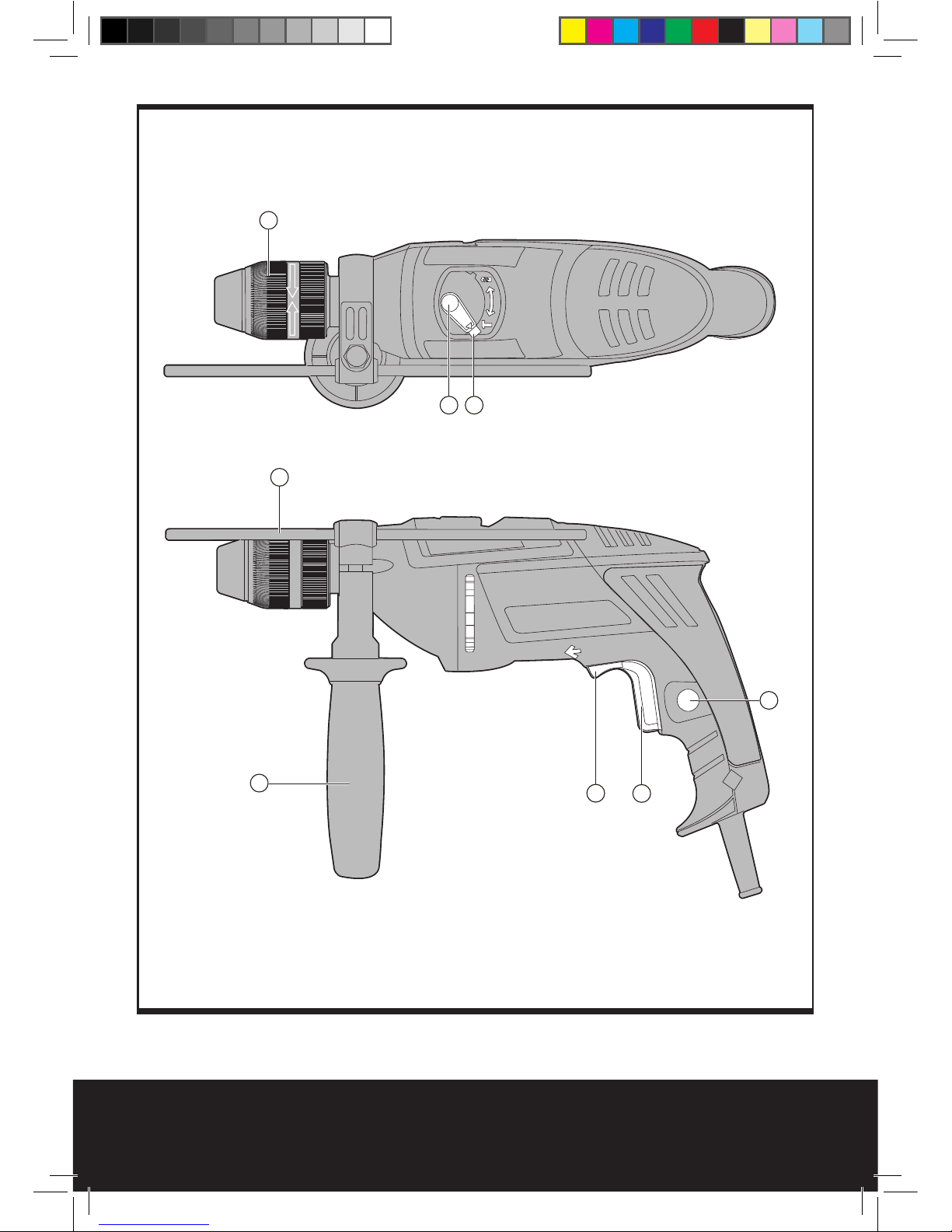
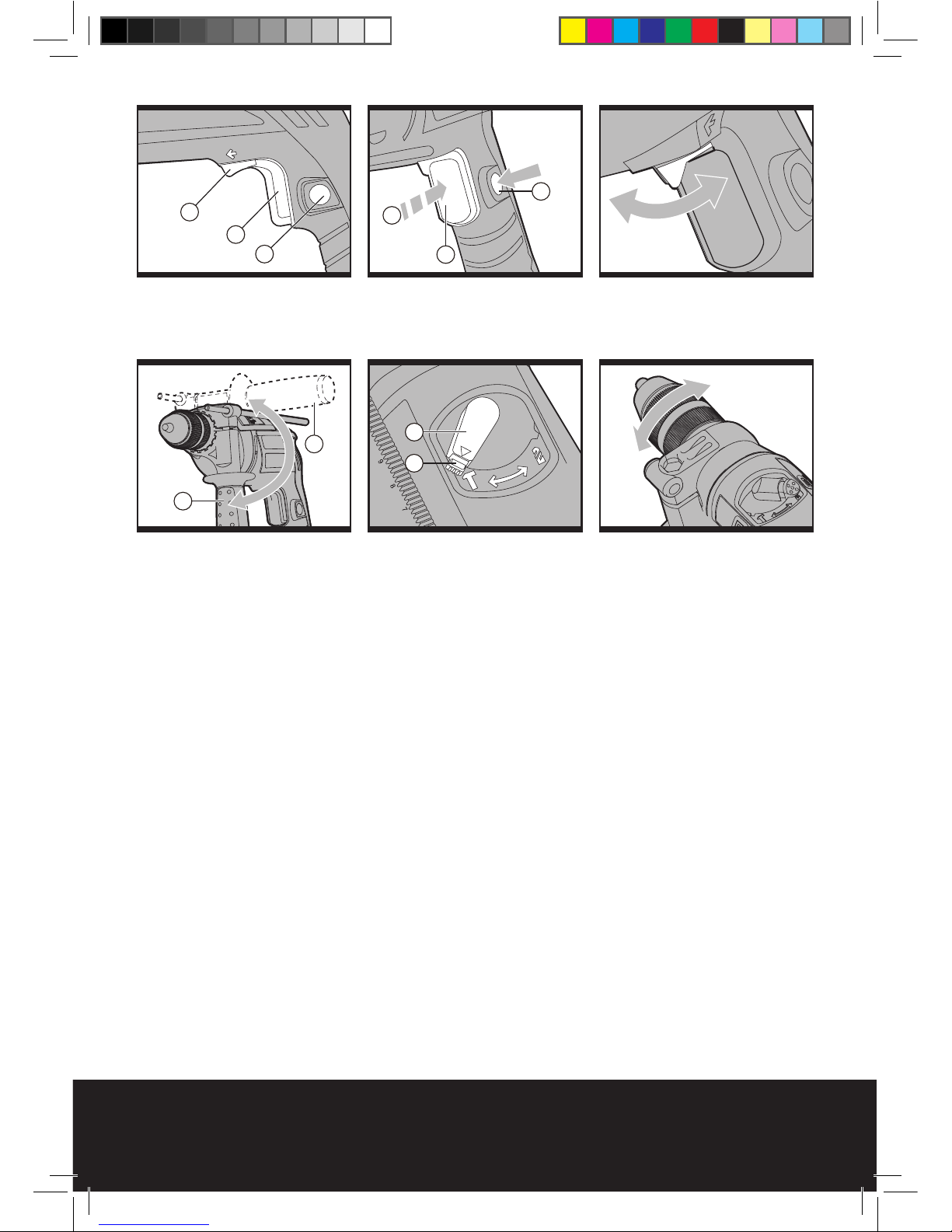
1. ON/OFF SWITCH
Depress to start and release to stop your tool.
(See A)
2. SWITCH LOCK-ON BUTTON
Depress on/off switch (1) then lock on button
(2) (See B); release on/off switch first and lock-
on button second. Your switch is now locked
on for continuous use. To switch off your tool
just depress and release the on/off switch.
3. FORWARD AND REVERSE ROTATION
CONTROL
For drilling and screwdriving use forward
rotation marked “ ” (lever is moved to
the left). Only use reverse rotation marked “
” (lever is moved to the right) to remove
screws or release a jammed drill bit. Never
change the direction of rotation when the tool
is rotating, wait until it has stopped. Never use
impact function when the tool is in reverse
rotation. (See C)
4. VARIABLE SPEED CONTROL
Adjust the on/off switch knob to increase or
decrease the speed according to the material
and accessory to be used (also possible
during no load operation). Low speed will give
lower torque and high speed gives higher
torque. (See B)
5. AUXILIARY HANDLE
Slide the handle onto the drill and rotate to
the desired working position. To clamp the
side handle rotates the handgrip clockwise.
To loose the side handle rotates the handgrip
anti-clockwise. Always use the side handle
when you use the tool. (See D)
6. HAMMER ACTION SELECTOR
When drilling masonry and concrete choose
the Hammer position . When drilling wood,
metal, plastic and screw driving choose the
Drill position .(See E)
7. CHUCK
To open the chuck jaws rotate the front section
of the chuck whilst holding the rear section.
Insert the drill bit between the chuck jaws
and rotate the front section in the opposite
direction whilst holding the rear section.
Ensure drill bit is in the centre of the chuck
jaws. Finally, firmly rotate the two separate
chuck sections in opposite directions. Your drill
bit is now locked in the chuck. (See F)
8. HAMMER/DRILL LOCKING BUTTON
To change between the hammer and drilling
selection positions you must push the locking
button in before rotating the selector to the
chosen position, ensuring that the button
springs back out to lock the selector when the
chosen position is reached. (See E)
9. DEPTH STOP
Fit the drill bit or driver bit into the chuck.
Loosen the depth stop by rotating the handle
anti-clockwise. Slide the depth stop until the
distance between the depth stop end and the
drill/driver bit end is equal to the depth of
hole/screw you wish to make. Then clamp the
depth stop by rotating the handle clockwise.
WORKING HINTS FOR YOUR
DRILL
If your power tool becomes too hot set the
speed to maximum and run no load for 2-3
minutes to cool the motor.
Tungsten carbide drill bits should always be
used for concrete and masonry.
When drilling in metal, only use HSS drill bits
in good condition.
Always use a magnetic bit holder when using
short screwdriver bits.
Where possible use a pilot hole before drilling
a large diameter hole.
MAINTENANCE
Your power tool requires no additional
lubrication or maintenance. There are no user
serviceable parts in your power tool. Never
use water or chemical cleaners to clean your
power tool. Wipe clean with a dry cloth.
Always store your power tool in a dry place.
Keep the motor ventilation slots clean. Keep
all working controls free of dust. If you see
0908
13L-WU300 M-20060904-·¨ÓïCE´¦ÐÞ¸Ä.indd 8 2007-3-5 16:01:33

Hammer drill ENG
sparks flashing in the ventilation slots, this is
normal and will not damage your power tool.
ENVIRONMENTAL
PROTECTION
Waste electrical products should not
be disposed of with household waste.
Please recycle where facilities exist.
Check with your local authorities or retailer for
recycling advice.
PLUG REPLACEMENT (UK &
IRELAND ONLY)
If you need to replace the fitted plug then
follow the instructions below.
IMPORTANT
The wires in the mains lead are colored in
accordance with the following code:
BLUE =NEUTRAL
Brown = Live
As the colors of the wires in the mains lead of
this appliance may not correspond with the
colored markings identifying the terminals
in your plug, proceed as follows. The wire
which is colored blue must be connected to
the terminal which is marked with N. The wire
which is colored brown must be connected to
the terminal which is marked with L.
Warning:
Never connect live or neutral wires to
the earth terminal of the plug. Only fit an
approved 13ABS1363/A plug and the correct
rated fuse.
Note: If a moulded plug is fitted and has to be
removed take great care in disposing of the
plug and severed cable, it must be destroyed
to prevent engaging into a socket.
Connect
Blue to N
(neutral)
Outer sleeve
firmly clamped
Cable grip
Brown L (live)
13 Amp fuse approved
to BS1362
DECLARATION OF CONFOR
MITY
We,
POSITEC Power Tools (Suzhou) Co., Ltd.
No. 11 Yangqing Road, Loufeng Area, Suzhou
Industrial Park,Jiangsu 215021, P. R. China
Declare that the product,
Description
WORX Hammer Drill
Type
WU300
Complies with the following Directives,
EC Machinery Directive
98/37/EC
EC Low Voltage Directive
73/23/EEC amended by 93/68/EEC
EC Electromagnetic Compatibility Directive
89/336/EEC amended by 93/68/EEC
Standards conform to:
EN55014-1
EN55014-2
EN61000-3-2
EN61000-3-3
EN60745-1
EN60745-2-1
2006/01/01
Jacky Zhou
POSITEC Quality Manager
0908
13L-WU300 M-20060904-·¨ÓïCE´¦ÐÞ¸Ä.indd 9 2007-3-5 16:01:34

Schlagbohrmaschine D
1110
Spannung 220V-240V ~ 50Hz/60Hz
Nennaufnahmeleistung 800W
Leerlaufdrehzahl 0-2800min-1
Nennschlagzahl 0-44800bpm
Max. spannweite des bohrfutters. 13mm
Max. bohrleistung. holz 35mm
mauerwerk 20mm
stahl 13mm
Schutzisoliert
Gewicht 2.5Kg
LÄRMPEGEL UND VIBRATIONEN
Gewichteter schalldruck 95dB (A)
Gewichtete schallleistung 106dB (A)
Tragen sie bei einem schalldruck über einen gehörschutz. 85dB (A)
Typischer gewichteter vibrationswert 10 m/s2
TECHNISCHE DATEN
ZUBEHÖRTEILE
Handgriff vorne 1
Tiefenanschlag 1
Wir empfehlen Ihnen, sämtliche Zubehörteile beim selben Fachhändler zu beziehen, bei dem
Sie auch Ihr Elektrowerkzeug gekauft haben. Verwenden Sie nur hochwertige Zubehörteile von
namhaften Herstellern. Die Güteklasse muss entsprechend der Anwendung gewählt werden.
Weitere Informationen finden Sie auf der Verpackung der Zubehörteile. Auch Ihr Fachhändler
berät Sie gerne.
1. EIN/AUS-SCHALTER
2. EINSCHALTSPERRE
3. VORWÄRTS-RÜCKWÄRTSLAUF-REGELUNG
4. DREHZAHLREGULIERUNG
5. HANDGRIFF VORNE
6. UMSCHALTER BOHREN-SCHLAGBOHREN
7. BOHRFUTTER
8. ARRETIERKNOPF
9. TIEFENANSCHLAG
13L-WU300 M-20060904-·¨ÓïCE´¦ÐÞ¸Ä.indd 10 2007-3-5 16:01:35

Schlagbohrmaschine D
1110
ZUSÄTZLICHE
SICHERHEITSHINWEISE
FÜR IHRE
SCHLAGBOHRMASCHINE
1. Ziehen Sie den Stecker aus der Steckdose,
ehe Sie Einstellungsänderungen,
Reparatur- oder Wartungsarbeiten
durchführen.
2. Wickeln Sie das Verlängerungskabel
von der Trommel, um eine mögliche
Überhitzung zu vermeiden.
3. Falls ein Verlängerungskabel erforderlich
ist, verwenden Sie ein funktionstüchtiges,
zugelassenes Verlängerungskabel, das für
die Leistung des Werkzeugs ausreichend
ist.
4. Kontrollieren Sie, ob die Netzspannung
der auf dem Typenschild angegebenen
Spannung entspricht.
5. Das Werkzeug ist schutzisoliert. Dies
bietet zusätzlichen Schutz vor möglichen
Kurzschlüssen im Werkzeug.
6. Prüfen Sie vor dem Arbeiten in Wänden
und Decken den genauen Verlauf von
Stromkabeln oder Rohrleitungen.
7. Zugängliche Metallteile und Zubehörteile
können bei längerem Gebrauch sehr heiß
werden.
8. Tragen Sie beim Arbeiten mit diesem
Werkzeug eine Schutzbrille.
9. Tragen Sie Gehörschutz bei der
Arbeit mit Schlagbohrmachinen.
Lärmaussetzung kann Gehörverlust
verursachen.
10. Benutzen Sie den zusätzlichen
Handgriff, der mit dem Werkzeug
geliefert wird. Kontrollverlust kann
Personenschäden zufolge haben.
11. Halten Sie das Werkzeug nur an den
isolierten griffigen Oberflächen, wenn
Sie einen Einsatz durchführen, bei
dem Schneidwerkzeuge eventuell
versteckte Kabel berühren könnten.
Berührung mit einem unter Strom
stehenden Kabel kann auch die Metallteile
des Gerätes unter Strom setzen und dem
Bedienenden einen Stromschlag versetzen.
SYMBOLE
Bedienungsanleitung lesen
Schutzisolation
Warnung
Schutzbrille tragen
Gehörschutz tragen
Schutzmaske tragen
13L-WU300 M-20060904-·¨ÓïCE´¦ÐÞ¸Ä.indd 11 2007-3-5 16:01:35

Schlagbohrmaschine D
BETRIEB
1. EIN/AUS-SCHALTER
Drücken Sie, um das Werkzeug zu starten und
lassen Sie los, um es abzuschalten. (siehe A)
2. EINSCHALTSPERRE
Drücken Sie den An/Aus-Schalter (1) und
dann die Einschaltsperre (2) (siehe B). Lassen
Sie zuerst den An/Aus-Schalter und dann die
Einschaltsperre los. Ihr Schalter ist nun im
Dauerbetrieb eingerastet. Um Ihr Werkzeug
abzuschalten, drücken Sie einfach den An/Aus-
Schalter und lassen Sie ihn wieder los.
3. VORWÄRTS-RÜCKWÄRTSLAUF-REGE-
LUNG
Zum Bohren und Schrauben nutzen Sie den
Vorwärtslauf, dieser ist markiert als “ ”
(Hebel ist zur linken Seite umgelegt). Nutzen
Sie die Rücklauffunktion, markiert als “
“ (Hebel ist zur rechten Seite umgelegt)
nur, um Schrauben herauszudrehen oder
um eingeklemmte Bohrer herauszuholen.
(siehe C) Wechseln Sie die Drehrichtung
niemals, während der Bohrer läuft.
Warten Sie, bis der Bohrer ausgelaufen
ist.
4. DREHZAHLREGULIERUNG
Justieren Sie den Knopf, um die Drehzahl
zu erhöhen oder zu verringern, je nach
Material und Zubehör, das Sie verwenden
(auch während Leerlaufbetrieb möglich). Dies
ermöglicht Ihnen, die maximale Drehzahl
mit dem verstellbaren Drehzahlregler
voreinzustellen. Dies reduziert das Risiko des
Abrutschens eines Bohrers/ Schrauberbits
und damit das Beschädigen des Werkstückes.
Niedrige Geschwindigkeit bewirkt niedriges
Drehmoment und hohe Geschwindigkeit
bewirkt niedriges Drehmoment.(siehe B)
5. HANDGRIFF VORNE
Schieben Sie den Handgriff auf den
Bohrerhals und drehen Sie ihn in die
gewünschte Position. Um den Seitengriff
festzuklemmen, drehen Sie den Handgriff
gegen den Uhrzeigersinn. Um den Seitengriff
zu lösen, drehen Sie den Handgriff im
Uhrzeigersinn. Benutzen Sie immer den
Hilfsgriff (siehe D).
6. UMSCHALTER BOHREN-
SCHLAGBOHREN
Wenn Sie Mauerwerk oder Beton bohren,
wählen Sie die Schlagbohrfunktion.
Wenn Sie Holz, Metall oder Kunststoff bohren
bzw. schrauben wollen, wählen Sie die
Bohrfunktion. (siehe E)
7. BOHRFUTTER
Um das Bohrfutter zu öffnen, drehen Sie
den vorderen Teil des Bohrfutters, während
Sie gleichzeitig den hineren Teil festhalten.
Stecken Sie den Bohrer in das Bohrfutter,
halten Sie den hinteren Teil des Bohrfutters
fest und drehen Sie den vorderen Teil in
entgegengesetzter Richtung. Achten Sie
darauf, dass der Bohrer in der Mitte des
Bohrfutters sitzt. Zuletzt drehen Sie beide Teile
des Bohrfutters fest in entgegengesetzten
Richtungen. Der Bohrer sitzt nun fest im
Bohrfutter. (siehe F)
8. ARRETIERKNOPF
Wenn Sie zwischen Bohren und Schlagbohren
wechseln möchten, müssen Sie zunächst
den Arretierknopf eindrücken, ehe Sie den
Hebel in die neue Position bringen können.
Achten Sie darauf, dass der Arretierknopf
wieder herausspringt, wenn der Hebel in der
gewünschten Position ist. (Siehe E)
9. EINSTELLBARER TIEFENANSCHLAG
Passen Sie den Bohrer oder Schrauberbit
in das Bohrfutter ein. Lösen Sie den
Tiefenanschlag, indem Sie den Handgriff
gegen den Uhrzeigersinn drehen.
Verschieben Sie den Tiefenanschlag, bis
die Entfernung zwischen Tiefenanschlag
und Bohrer/ Schrauberbit der gewünschten
Bohrtiefe entspricht. Klemmen Sie dann den
Tiefenanschlag fest, indem Sie den Handgriff
gegen den Uhrzeigersinn drehen.
1312
13L-WU300 M-20060904-·¨ÓïCE´¦ÐÞ¸Ä.indd 12 2007-3-5 16:01:36

Schlagbohrmaschine D
ARBEITSHINWEISE
FÜR IHRE
SCHLAGBOHRMASCHINE
Wenn die Schlagbohrmaschine zu heiß
wird, lassen Sie ihn 2-3 Minuten im Leerlauf
laufen, um den Motor abzukühlen. Wolfram-
Karbid Bohrer sollten immer für Beton und
Mauerwerk benutzt werden. Wenn Sie in
Metall bohren, verwenden Sie nur HSS-
Bohrer in gutem Zustand. Immer einen
magnetischen Bithalter verwenden, wenn Sie
kurze Schraubendreherbits verwenden. Wenn
möglich, immer ein Loch vorbohren, wenn Sie
große Durchmesser bohren möchten.
WARTUNG
Ihr Werkzeug benötigt keine zusätzliche
Schmierung oder Wartung. Es enthält keine
Teile, die Sie warten müssen. Reinigen
Sie Ihr Werkzeug niemals mit Wasser oder
chemischen Reinigungsmitteln. Wischen Sie
es mit einem trockenen Tuch sauber. Lagern
Sie Ihr Werkzeug immer an einem trockenen
Platz. Halten Sie die Lüftungsschlitze sauber.
Gelegentlich sind durch die Lüftungsschlitze
hindurch Funken zu sehen. Dies ist normal
und wird Ihr Werkzeug nicht beschädigen.
UMWELTSCHUTZ
Elektroprodukte dürfen nicht mit dem
normalen Haushaltsmüll entsorgt
werden, sondern sollten nach
Möglichkeit zu einer Recyclingstelle gebracht
werden. Ihre zuständigen Behörden oder
Ihr Fachhändler geben Ihnen hierzu gerne
Auskunft.
KONFORMITÄTSERKLÄRUNG
Wir,
POSITEC Power Tools (Suzhou) Co., Ltd.
No. 11 Yangqing Road, Loufeng Area, Suzhou
Industrial Park, Jiangsu 215021, P. R. China
erklären hiermit, dass unser Produkt
Beschreibung
WORX Schlagbohrmaschine
Typ
WU300
Den Bestimmungen der folgenden Richtlinien
entspricht:
EC Maschinenrichtlinie
98/37/EC
EC Niederspannungsrichtlinie
73/23/EEC geändert durch 93/68/EEC
EC EMV-Richtlinie
89/336/EEC geändert durch 93/68/EEC
Werte nach:
EN55014-1
EN55014-2
EN61000-3-2
EN61000-3-3
EN60745-1
EN60745-2-1
2006/01/01
Jacky Zhou
POSITEC Qualitätsleiter
1312
13L-WU300 M-20060904-·¨ÓïCE´¦ÐÞ¸Ä.indd 13 2007-3-5 16:01:36

Trapano a Percussione I
Tensione nominale 220V-240V ~ 50Hz/60Hz
Potenza nominale 800W
Velocità nominale a vuoto 0-2800min-1
Velocità impatto 0-44800bpm
Capacità massima mandrino 13mm
Capacità massima di foratura legno 35mm
muratura 20mm
acciaio 13mm
Doppio isolamento
Peso 2.5Kg
DATI SULLA RUMOROSITÀ E SULLE VIBRAZIONI
Livello di pressione acustica ponderata A 95dB (A)
Potenza acustica ponderata A 106dB (A)
Indossare protezione per le orecchie quando la pressione sonora è superiore a 85dB (A)
La vibrazione ponderata tipica è di 10 m/s2
DATI TECNICI
ACCESSORI
Impugnatura ausiliaria 1
Limitatore profondità 1
Si raccomanda di acquistare tutti gli accessori nello stesso negozio in cui è stato acquistato
l’attrezzo. Usare accessori di buona qualità e di marca rinomata. Fare riferimento alla confezione
dell’accessorio per altri dettagli. Il personale del negozio può aiutarvi e consigliarvi.
1. INTERRUTTORE D’ACCENSIONE/SPEGNIMENTO
2. PULSANTE DI BLOCCO
3. CONTROLLO ROTAZIONE AVANTI ED INDIETRO
4. INTERRUTTORE VELOCITÀ VARIABILE (si veda la figura B)
5. IMPUGNATURA AUSILIARIA
6. SELETTORE PERCUSSIONE O TRAPANATURA
7. MANDRINO
8. INTERRUTTORE DI BLOCCO SU TRAPANO E PERCUSSIONE
9. ASTA DI PROFONDITÀ
1514
13L-WU300 M-20060904-·¨ÓïCE´¦ÐÞ¸Ä.indd 14 2007-3-5 16:01:37

Trapano a Percussione I
1514
NORME DI SICUREZZA
SUPPLEMENTARI RELATIVE
ALL’USO DEL TRAPANO
1. Rimuovere la spina dalla presa di corrente
prima di eseguire qualsiasi regolazione,
riparazione o manutenzione.
2. Estrarre completamente il cavo di
prolunga dal suo alloggio per evitare il
surriscaldamento.
3. In caso di utilizzo di un cavo prolunga,
verificare sempre il corretto amperaggio
rispetto all’elettroutensile e che sia in
buone condizioni.
4. Accertarsi che la tensione di alimentazione
di rete corrisponda a quanto riportato sulla
targhetta delle specifiche.
5. L’attrezzo ha un doppio isolamento per
la protezione da possibili guasti al suo
interno.
6. Controllare sempre pareti e soffitti per
evitare tubature e cavi nascosti.
7. Dopo periodi prolungati d’attività, le parti
metalliche esterne e gli accessori possono
diventare caldi.
8. Indossare occhiali per la protezione degli
occhi quando si usa questo attrezzo.
9. Indossare protezioni per le orecchie
con tutti i trapani a percussione.
L’esposizione al rumore può provocare
lperdita dell’udito.
10. Usare le impugnature ausiliarie fornite
in dotazione all’attrezzo. La perdita di
controllo può provocare lesioni personali.
11. Afferrare lo strumento per le parti
isolate quando si eseguono operazioni
durante le quali l’attrezzo potrebbe
entrare in contatto con cavi nascosti.
Il contatto con cavi elettrici in tensione
espone l’operatore al rischio di scosse
elettriche.
SIMBOLI
Leggere il manuale
Doppio isolamento
Attenzione
Indossare protezione per gli
occhi
Indossare protezione per le
orecchie
Indossare una mascherina
antipolvere
13L-WU300 M-20060904-·¨ÓïCE´¦ÐÞ¸Ä.indd 15 2007-3-5 16:01:37

Trapano a Percussione I
ISTRUZIONI OPERATIVE
1. INTERRUTTORE D’ACCENSIONE/
SPEGNIMENTO
Premerlo per avviare l’attrezzo e rilasciarlo per
disattivarlo. (Fare riferimento alla figura A)
2. PULSANTE DI BLOCCO
Premere l’interruttore d’accensione/
spegnimento (1) e poi il tasto si blocco su
accensione (2) (si veda la figura B); rilasciare
prima l’interruttore d’accensione/spegnimento
e poi il tasto si blocco su accensione. Il tasto
ora è bloccato per l’uso continuato. Per
disattivare l’attrezzo, premere e rilasciare
l’interruttore d’accensione/spegnimento.
3. CONTROLLO ROTAZIONE AVANTI ED
INDIETRO
Per trapanare ed avvitare usare la rotazione
avanti contrassegnata da “ ” (la leva è
spostata sulla sinistra). Usare la rotazione
inversa, contrassegnata da “ ” (la leva
è spostata sulla destra), solamente per
rimuovere le viti o le punte del trapano
bloccate. Non cambiare mai la direzione di
rotazione quando l’attrezzo è in movimento;
attendere affinché si sia fermato. Non usare
mai la funzione di percussione quando
l’attrezzo è impostato sulla rotazione inversa.
(Si veda la figura C)
4. CONTROLLO VELOCITÀ VARIABILE
Regolare l’interruttore d’accensione/
spegnimento per aumentare o diminuire la
velocità in base al materiale ed agli accessori
usati (è possibile anche durante le operazioni
a vuoto). Una minore velocità produrrà una
coppia minore, mentre una maggiore velocità
produrrà una coppia maggiore. (Si veda la
figura B)
5. IMPUGNATURA AUSILIARIA
Inserire l’impugnatura facendola scorrere
sull’attrezzo e ruotarla sulla posizione
operativa desiderata. Per fissare l’impugnatura
laterale, ruotarla in senso orario. Per allentare
l’impugnatura laterale, ruotarla in senso
antiorario. Utilizzare sempre l’impugnatura
laterale quando si usa l’attrezzato. (Si veda la
figura D)
6. SELETTORE AZIONE DI PERCUSSIONE
Quando si trapana su murature e calcestruzzo,
scegliere la posizione “Percussione”.
Quando si trapana su legno, metallo,
plastica e quando l’attrezzo è usato come un
avvitatore, scegliere la posizione “Trapano”.
(Si veda la figura E)
7. MANDRINO
Per aprire le ganasce del mandrino ruotare
la sezione frontale del mandrino mentre si
tiene ferma la sezione posteriore. Inserire la
punta tra le ganasce del mandrino e ruotare
la sezione frontale in direzione opposta
mentre si tiene ferma la sezione posteriore.
Assicurarsi che la punta sia collocata al centro
delle ganasce del mandrino. Infine, ruotare
con fermezza ed in direzione opposta le due
sezioni separate del mandrino. Adesso la
punta è bloccata nel mandrino. (Si veda la
figura F)
8. PULSANTE DI SICUREZZA FUNZIONE
TRAPANO / PERCUSSIONE
Per cambiare tra le posizioni di percussione
e trapanatura, è necessario premere
l’interruttore di blocco prima di ruotare
il selettore sulla posizione desiderata, ed
accertarsi che l’interruttore torni alla posizione
originale per bloccare il selettore una volta
raggiunta la posizione scelta. (Si veda la figura
E)
9. ASTA DI PROFONDITÀ
Inserire la punta o l’utensile nel mandrino.
Allentare l’asta di profondità ruotando
l’impugnatura in senso antiorario. Far scorrere
l’asta di profondità finché la distanza tra l’asta
e la punta/utensile è uguale alla profondità
del foro che si vuole trapanare/vite che si
vuole insediare. Infine bloccare l’asta di di
profondità ruotando l’impugnatura in senso
orario.
CONSIGLI SUL
FUNZIONAMENTO DEL
TRAPANO
Se l’attrezzo diventa troppo caldo, impostare
1716
13L-WU300 M-20060904-·¨ÓïCE´¦ÐÞ¸Ä.indd 16 2007-3-5 16:01:38

Trapano a Percussione I
la velocità al massimo e farlo funzionare a
vuoto per 2-3 minuti per raffreddare il motore.
Le punte di carburo di tungsteno devono
essere usate sempre quando si lavora su
calcestruzzo e muratura.
Quando si trapana il metallo, usare solamente
punte HSS in buone condizioni.
Usare sempre un portainserti magnetico
quando si usano punte corte.
Dove possibile, usare fori pilota prima di
trapanare buchi di diametro maggiore.
MANUTENZIONE
L’attrezzo non richiede di lubrificazione
o manutenzione aggiuntiva. All’interno
dell’attrezzo non ci sono parti riparabili da
parte dell’utente. Non usare mai acqua o
detergenti chimici per pulire l’attrezzo. Pulire
con un panno asciutto. Riporre sempre gli
attrezzi elettrici in luoghi asciutti. Tenere pulite
le aperture di ventilazione del motore. Tenere
puliti dalla polvere tutti i controlli operativi.
La formazione di scintille all’interno delle
aperture di ventilazione, è un fenomeno
normale che non crea danni all’attrezzo.
PROTEZIONE AMBIENTALE
I prodotti elettrici obsoleti non devono
essere smaltiti insieme ai rifiuti urbani.
Riciclare i prodotti laddove sono
presenti gli appositi centri. Mettersi in contatto
con le autorità locali, o con il rivenditore, per
informazioni sul riciclaggio.
DICHIARAZIONE DI
CONFORMITÀ
POSITEC Power Tools (Suzhou) Co., Ltd.
No. 11 Yangqing Road, Loufeng Area, Suzhou
Industrial Park, Jiangsu 215021, P. R. China
Dichiara che l’apparecchio ,
Descrizione
WORX Trapano a Percussione
Codice
WU300
È conforme alle seguenti direttive,
Direttiva macchine
98/37/EC
Direttiva sulla bassa tensione
73/23/EEC modificata dalla 93/68/EEC
Direttiva sulla compatibilità elettromagnetica
89/336/EEC modificata dalla 93/68/EEC
Conforme a:
EN55014-1
EN55014-2
EN61000-3-2
EN61000-3-3
EN60745-1
EN60745-2-1
2006/01/01
Jacky Zhou
POSITEC Direttore Qualità
1716
13L-WU300 M-20060904-·¨ÓïCE´¦ÐÞ¸Ä.indd 17 2007-3-5 16:01:38

Perceuse Percussion F
1918
1918
Tension nominale- fréquence 220V-240V ~ 50Hz/60Hz
Puissance 800W
Vitesse à vide 0-2800min-1
Cadence de frappe nominale 0-44800bpm
Capacité max. du mandrin 13mm
Capacité max de perçage bois 35mm
béton 20mm
acier 13mm
Double isolation
Poids de la machine 2.5Kg
DONNEES SUR LE BRUIT ET LES VIBRATIONS
Niveau de pression sonore mesurée 95dB (A)
Niveau de puissance sonore mesurée 106dB (A)
Portez un casque anti-bruit lorsque la pression sonore est supérieure à 85dB (A)
Valeur de vibration mesurée 10 m/s2
CARACTERISTIQUES TECHNIQUES
ACCESSOIRES
Poignée auxiliaire 1
Butée de profondeur 1
Nous recommandons d’acheter tous les accessoires dans le magasin où l’outil a été acheté.
Utilisez des accessoires de bonne qualité et de marque.
Choisissez les meules adaptées au travail à réaliser. Reportez vous à l’emballage pour de plus
amples informations. Le personnel du magasin peut apporter aide et conseils.
1. INTERRUPTEUR
2. INTERRUPTEUR AVEC DISPOSITIF DE VERROUILLAGE
3. COMMANDE DE ROTATION AVANT ET INVERSEE
4. COMMANDE A VITESSE VARIABLE
5. POIGNÉE AUXILIAIRE
6. SELECTEUR D’ACTION DU MARTEAU
7. MANDRIN
8. BOUTON DE VERROUILLAGE DU MARTEAU PERFORMATEUR
9. BUTÉE DE PROFONDEUR
13L-WU300 M-20060904-·¨ÓïCE´¦ÐÞ¸Ä.indd 18 2007-3-5 16:01:39

1918
Perceuse Percussion F
1918
MESURES DE SECURITE
SUPPLEMENTAIRES POUR
LA PERCEUSE
1. Débrancher la prise avant d’effectuer des
réglages, des réparations ou d’entretiens
de l’outil.
2. Dérouler entièrement le câble d’extension
afin d’éviter toute surchauffe éventuelle.
3. Lorsqu’une rallonge est nécessaire,
s’assurer qu’elle a le bon ampérage pour
votre outil et qu’elle est en bon état.
4. S’assurer que le voltage de votre source
d’alimentation est le même que celui de
votre outil.
5. Votre outil possède une double isolation
pour une meilleure protection contre
les éventuelles défaillances d’isolation à
l’intérieur de votre outil.
6. Toujours vérifier les murs et les plafonds
afin de voir s’il y a des câbles et tuyaux
cachés.
7. A la suite de longues périodes de travail,
les parties externes en métal et accessoires
pourraient être chauds.
8. Porter toujours des lunettes de protection.
9. Veuillez porter un casque anti-bruit
lorsque vous utilisez une perceuse
à percussion. L’exposition au bruit peut
causer la perte de l’audition.
10. Veuillez utiliser les poignées
auxiliaires fournies avec l’outil. La perte
de contrôle peut engendrer des blessures.
11. Tenir l’outil par les surfaces
antidérapantes et isolées lorsque
l’outil de coupe risque d’entrer en
contact avec des câbles cachés.
L’entrée en contact d’un câble sous tension
rendra les parties en métal de l’outil
également sous tension et l’utilisateur
pourrait subir une décharge électrique.
SYMBOLES
Lire le manuel
Double isolation
Avertissement
Porter des lunettes de protection
Porter un casque anti-bruit
Porter un masque anti-poussière
13L-WU300 M-20060904-·¨ÓïCE´¦ÐÞ¸Ä.indd 19 2007-3-5 16:01:39

Perceuse Percussion F
2120
2120
FONCTIONNEMENT
1. INTERRUPTEUR MARCHE/ARRET
Appuyer sur le bouton pour démarrer l’outil et
relâcher pour l’arrêter. (Voir Fig A)
2. INTERRUPTEUR AVEC DISPOSITIF DE
VERROUILLAGE
Appuyer sur l’interrupteur de marche/arrêt
(1) puis verrouiller le bouton (2) (Voir Fig B),
relâcher d’abord l’interrupteur de marche/arrêt
puis le deuxième bouton. L’interrupteur est
maintenant verrouillé pour une utilisation
continue. Pour arrêter l’outil, appuyer et
relâcher l’interrupteur de marche/arrêt.
3. COMMANDE DE ROTATION AVANT ET
INVERSEE
Pour percer et visser, utiliser la rotation
avant indiquée par un “ “ (le levier est
placé sur la gauche). Utiliser seulement la
rotation inversée indiquée par un “ “ (le
levier est placé sur la droite) pour retirer des
vis ou dégager une mèche bloquée (le levier
est déplacé sur la droite) Ne jamais changer
le sens de rotation lorsque l’outil tourne,
attendre qu’il soit arrêté. (Voir Fig C)
4. COMMANDE A VITESSE VARIABLE
Appuyer sur le bouton pour augmenter
ou diminuer la vitesse selon le matériau et
l’accessoire utilisés (également possible au
cours d’une opération à vide). Ceci vous
permet de prédéfinir la vitesse maximale de
votre gâchette de vitesse variable. Ceci réduit
le risque de glissage de la perceuse/foret et
d’endommager l’unité de travail. Une faible
vitesse donnera un couple bas et une forte
vitesse donnera un couple élevé (Voir Fig B).
5. POIGNÉE AUXILIAIRE
Faire glisser la poignée sur la perceuse et
la faire pivoter jusqu’à la position désirée.
Pour fixer la poignée latérale, faire tourner
la poignée dans le sens inverse des aiguilles
d’une montre. Pour desserrer la poignée
latérale faire tourner la poignée dans le sens
des aiguilles d’une montre. Toujours utiliser la
poignée latérale (Voir Fig D).
6. SELECTEUR D’ACTION DU MARTEAU
Lors du perçage de maçonnerie et de béton,
choisir la position marteau. Lors du perçage
de bois, métal, plastique et lors du vissage,
choisir la position perceuse. (Voir Fig E)
7. MANDRIN
Pour ouvrir les mors, tournez la section avant
du mandrin pendant que vous tenez la section
arrière. Insérer le foret de la perceuse entre
les mors et tournez la section avant dans la
direction opposée pendant que vous tenez la
section arrière. Assurez-vous que le foret de
la perceuse est dans le centre des mors du
mandrin. Finalement, tournez fermement les
deux sections séparées du mandrin dans des
directions opposées. Votre foret de perceuse
est maintenant bloqué dans le mandrin. (Voir
Fig F)
8. BOUTON DE VERROUILLAGE DU
MARTEAU PERFORATEUR
Pour passer de la position de selection du
marteau ou de la perceuse, vous devez
appuyer sur le bouton de verrouillage avant
de tourner le sélecteur à la position voulue,
en vous assurant que le bouton ressorte pour
verrouiller le sélecteur dans la position voulue
est obtenue (voir Fig. E)
9. BUTEE DE PROFONDEUR
Insérez le foret ou la mèche sur le mandrin.
Desserrez le buteur de profondeur en tournant
la poignée dans le sens des aiguilles d’une
montre. Faites glisser l’arrêt de profondeur
jusqu’à ce que la distance entre l’arrêt de
profondeur et le foret/mèche soient égaux à la
profondeur du trou/tournevis que vous désirez
faire ou insérer. Ensuite serrez le buteur de
profondeur en tournant la poignée dans le
sens inverse des aiguilles d’une montre.
CONSEIL D’UTILISATION DE
LA PERCEUSE
Si l’outil motorisé devient trop chaud, régler
la vitesse sur le maximum et le faire tourner
à vide pendant 2-3 minutes pour refroidir le
moteur. Les mèches en carbure de tungstène
doivent toujours être utilisées pour le béton
13L-WU300 M-20060904-·¨ÓïCE´¦ÐÞ¸Ä.indd 20 2007-3-5 16:01:40
Table of contents
Languages:
Other Worx Drill manuals