manuals.online logo
Brands
  1. Home
  2. •
  3. Brands
  4. •
  5. Wyrestorm
  6. •
  7. Extender
  8. •
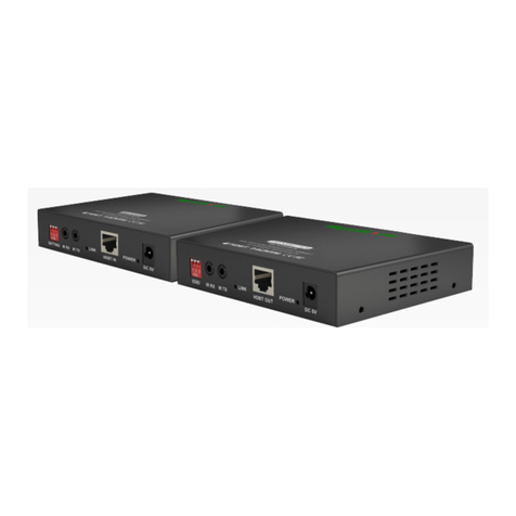
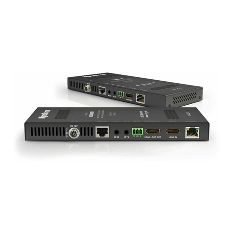
  9. Wyrestorm HDBT EX-1UTP-IR-100 User manual

Wyrestorm HDBT EX-1UTP-IR-100 User manual

For transmission of internet - connect an Ethernet cable
from your internet source to the Ethernet port on the
T ANSMITTE balun.
Connect a good quality, well terminated and tested Cat
5e/6e cable with J45 connectors from the UTP OUT
port of the T ANSMITTE to the UTP IN port of the
ECEIVE . Ensure connectors are pushed securely into
each port and supported by the cable strain relief clip
to prevent loosening.
Attention: UTP cable must be correctly terminated to
568B standard at both ends (see diagram). Inadequate
cable quality or poor J45 termination leads to inter-
mittent performance and longer install times.
Connect the HDMI display output (such as: HD-
LCD/HD-DLP) to the HDMI OUT of the ECEIVE .
To view internet on the display - Connect another
Ethernet cable from the Ethernet port on the ECEIVE
to the corresponding HDMI input on your display.
Insert the I X 3.5mm jack into the I X port on the
ECEIVE . Discretely attach the I receiver to the
display with the adhesive backing, ensuring a clear line
of sight to the remote control being used. You may
need to adjust the position of the I X to achieve best
results.
Extending HDMI using Cat5e to 100 (328 ft)
with IR source control
Attention: Do Not Hotplug! - Please insert and extract
cables carefully with the power switched off.
Connecting and disconnecting cables while the unit is
powered can damage circuitry.
Connect the HDMI source input (such as: HD-DVD,
PS3, Cable/Sat box, Blu-ray etc.) to the HDMI IN of the
T ANSMITTE balun. Avoid excessive bending of the
HDMI cable and ensure connectors are inserted firmly
in all ports.
Attention: We strongly recommend using the supplied
mounting brackets to secure both baluns. Sudden
movement of these devices can lead to unnecessary
service call outs and loss of picture/sound due to stress
on connections.
Position the I TX emitter sensor over the infrared
receiving area of the source input and fix with the
adhesive backing. You may need to adjust the location
of the emitter later to achieve the best results –
sometimes moving the sensor to different areas on the
source facia can improve I performance.
Insert the I TX 3.5mm jack into the I TX port on the
T ANSMITTE balun.
Tip: you can locate the small, round infrared sensor by
shining a flashlight onto the facia of devices.
For two-way I (to control the display from the source
location) insert the I X 3.5mm jack into the I X
port on the T ANSMITTE balun and connect the
larger, rectangular I X receiver to the your chosen
control system. See 9.
1
2
3
4
HDBaseT Extender Set
Part Number EX-1UTP-I -100
5
6
7
!!
RS232 ETHERNETLINK DC5V
HDMI IN ETHERNET
IR
RX
IR
TX
HDMI IN ETHERNET
IR
RX
IR
TX
TO CONTROL
SYSTEM
POWER
POWER
TRANSMITTER
RECEIVER
REAR PANEL VIEW
REAR PANEL VIEW
ADDITIONAL
CONTROL OF
DISPLAY
THROUGH RS232
LAN
INTERNET
CONNECTION
TO RECEIVER
FROM TRANSMITTER
CONTROL
SYSTEM
1
2
3
4
5
6
7
9
10
11
8
10
10 10
CAT 5e/6 Cable up to 100m/328 ft
8
Two-way control – for the display to be controlled at
the source location, insert the I TX 3.5mm jack into
the I X port on the ECEIVE . Attach the emitter
directly over the infrared receiving area of the display
and fix with the adhesive backing. You may need to
adjust the location of the emitter later to achieve the
best results – sometimes moving the sensor to
different areas on the display facia can improve I
performance.
For S232 control – connect S232 cables from the
display to the ECEIVE and from the T ANSMITTE
to the control system being used.
Finally, add the provided 5V power supplies to both
T ANSMITTE and ECEIVE baluns. We do not recommend
passing power remotely over long cable distances as this can
affect the performance of the product.
Note: check the LED lights are lit to confirm the units are
powered and a signal link is established between the baluns.
Attention: Turn off all power to devices before you disconnect
any cables to avoid hotplugging that could damage circuitry.
Follow ‘last on first off’ protocol when connecting and discon-
necting cables.
IR Control
■Are IR emitters and receivers correctly positioned to allow infrared signals to be
transmitted and re-ceived through the baluns?
■Emitters should be fixed firmly over infrared sensors of sources. Transmitters should
be attached to displays ensuring a clear line of sight to the remote control used to
operate.
■Is your remote control powered and sending a signal? As IR is invisible to the naked
eye, check your remote is transmitting a signal by viewing the remote handset
sensor through a digital camera/camera phone – the sensor should flash when a
button on the handset is held down.
■IR signal dropout can be experienced due to exterior emissions of infrared radiation.
Ensure emitters and receivers are away from direct sunlight, halogen lighting and
plasma screens that may interfere with IR signals.
Safety Recommendations
■Do not expose this apparatus to any form of moisture, including the
placement of anything containing liquids on the unit. To prevent risk
of electric shock or fire hazard, ensure apparatus is installed in an
unobstructed, well-ventilated area away from any external heat
sources - including other electrical devices which may produce heat.
■Only use attachments / accessories specified by the manufacturer and
refer all servicing to qualified service personnel.
■Failure to adhere to these recommendations may invalidate your
warranty. Please see below for additional safety and warranty
information.
Warranty information
Thank you for choosing WyreStorm. This product is covered by a 2 year limited parts
and labour warranty. During this period there will be no charge for unit repair,
component replacement or complete product replacement in the event of
malfunction. The decision to repair or replace will be made by the manufacturer.
This limited warranty ONLY CO ERS defects in materials or workmanship and
excludes normal wear and tear or cosmetic damage.
www.wyrestorm.com
Troubleshooting
Regardless of manufacturer or product, the majority of installation diffi-
culties can typically be attribut-ed to communication problems between
devices or when high bandwidth transmissions are attempted with insuf-
ficient cable/connections. Should you find yourself in such a situation, we
have drawn up the following checklist of general issues and causes that
should help you shoot your way out of trouble without seeking further
assistance.
No or poor quality picture
■Are you connected and powered? Double check all HDMI, UTP and 5v
power connections are firmly inserted into correct ports and that all
devices are powered.
■Signal strength – can be affected if you are approaching the maximum
distance of your cable. Check your cable length is well within limits and
use an in line repeater if to boost your signal if necessary.
■Furthermore, the use of cable joins, stranded patch panels, wall outlets
and stranded patch leads as interconnects between them, can also signif-
icantly reduce signal strength. Use solid core straight, straight through
connections wherever possible.
■If you reduce the resolution of the source, do you get a picture? If so, this
suggests a conflicting reso-lution between source and display or a
bandwidth capacity issue with your cable. Check all inputs and outputs
share the same resolution and make sure the signal is being successfully
transmitted the full length of your cable run.
■Picture ‘snow’ / HD ‘noise’ – signifies a failure to fully establish a signal
and can often be caused by poorly terminated RJ45 connectors or
excessive cable lengths. Ensure your cable is correctly wired to 568B
standards. Try swapping in a display and receivers from a fully functioning
location – if the prob-lem continues on the same output, turn off all
equipment and swap your signal carrying cables at both ends.
■Cable quality and condition – HDMI cable/connectors can be easily
damaged and the quality of mate-rial can vary, especially in lower price
brackets. Always use good quality leads and cables and try swapping for
those already working to see if this improves your image.
■Blu-ray and 3D – make sure all your equipment has been configured and
enabled to transmit and ac-cept the signal. Are resolutions between
source and display compatible and cable adequate for the large
bandwidth required by Blu-ray and 3D transmissions?
For technical support, please call:
US: +866 677 0053 • UK: +44 (0) 1793 238 338 • Email: s pport@wyrestorm.com
PLEASE NOTE – All cable distances are on the basis of a direct runs of cable (no
patch panels or wall outlets). Please use good quality, solid conductor, Cat5e cable.
Stranded pre-made patch leads will reduce effectiveness of this product. Please
ensure Cat5e cables are installed to local electrical regulations. Close lying electrical
cables can effect product performance.
10
11
!
9
Cat5e Cable Perfor ance Guide
16ft 33ft49ft 66ft 82ft 98ft115ft131ft148ft164ft197ft230ft262ft295ft328ft
Cat5e Wiring Guide
The quality of termination
for every J45 is essential.
Poor terminations leads to
intermittent performance
and longer install times.

Other Wyrestorm Extender manuals

Wyrestorm ex-1utp-ir-70-AMP User manual

Wyrestorm

Wyrestorm ex-1utp-ir-70-AMP User manual

Wyrestorm EX-SW-0301-H2 User manual

Wyrestorm

Wyrestorm EX-SW-0301-H2 User manual

Wyrestorm EX-SDI-50 User manual

Wyrestorm

Wyrestorm EX-SDI-50 User manual

Wyrestorm EX0101-WH1 User manual

Wyrestorm

Wyrestorm EX0101-WH1 User manual

Wyrestorm EX-70-H2 User manual

Wyrestorm

Wyrestorm EX-70-H2 User manual

Wyrestorm EX-70-G2 Series User manual

Wyrestorm

Wyrestorm EX-70-G2 Series User manual

Wyrestorm EX-100-H2-PRO User manual

Wyrestorm

Wyrestorm EX-100-H2-PRO User manual

Wyrestorm EX-40-G2 User manual

Wyrestorm

Wyrestorm EX-40-G2 User manual

Wyrestorm EX-1UTP-IR-40 User manual

Wyrestorm

Wyrestorm EX-1UTP-IR-40 User manual

Wyrestorm EX-70-H2X User manual

Wyrestorm

Wyrestorm EX-70-H2X User manual

Wyrestorm EX-1UTP-IR-50-POH User manual

Wyrestorm

Wyrestorm EX-1UTP-IR-50-POH User manual

Wyrestorm Express exp-EX-HDBT-50 User manual

Wyrestorm

Wyrestorm Express exp-EX-HDBT-50 User manual

Wyrestorm EX-35-H2 User manual

Wyrestorm

Wyrestorm EX-35-H2 User manual

Wyrestorm EX-1UTP-IR-50-POH User manual

Wyrestorm

Wyrestorm EX-1UTP-IR-50-POH User manual

Wyrestorm EX-80-KVM User manual

Wyrestorm

Wyrestorm EX-80-KVM User manual

Wyrestorm eX-70-4K User manual

Wyrestorm

Wyrestorm eX-70-4K User manual

Wyrestorm EX-1UTP-IR-70 Manual

Wyrestorm

Wyrestorm EX-1UTP-IR-70 Manual

Wyrestorm EX-SW-0201-4K User manual

Wyrestorm

Wyrestorm EX-SW-0201-4K User manual

Wyrestorm EX-100-H2 User manual

Wyrestorm

Wyrestorm EX-100-H2 User manual

Wyrestorm EX-35-4K User manual

Wyrestorm

Wyrestorm EX-35-4K User manual

Wyrestorm EX-35-H2 User manual

Wyrestorm

Wyrestorm EX-35-H2 User manual

Wyrestorm EXP-EX-COAX-50 User manual

Wyrestorm

Wyrestorm EXP-EX-COAX-50 User manual

Wyrestorm EX-35-4K User manual

Wyrestorm

Wyrestorm EX-35-4K User manual

Wyrestorm EX-40-G3 User manual

Wyrestorm

Wyrestorm EX-40-G3 User manual

Popular Extender manuals by other brands

Hunter 9043 user manual

Hunter

Hunter 9043 user manual

StarTech.com 410VDSLEXT manual

StarTech.com

StarTech.com 410VDSLEXT manual

on networks N300RE user manual

on networks

on networks N300RE user manual

SSS Siedle BVS 650-01 Product information

SSS Siedle

SSS Siedle BVS 650-01 Product information

Leviton PE400-1 installation instructions

Leviton

Leviton PE400-1 installation instructions

D-Link E15 Quick installation guide

D-Link

D-Link E15 Quick installation guide

KanexPro EXT-HDBASE70E user manual

KanexPro

KanexPro EXT-HDBASE70E user manual

Cypress Semiconductor CY3242-IOXlite Kit Guide

Cypress Semiconductor

Cypress Semiconductor CY3242-IOXlite Kit Guide

Atlona AT-DVIDF40SR user manual

Atlona

Atlona AT-DVIDF40SR user manual

ZUUM AE1-T quick guide

ZUUM

ZUUM AE1-T quick guide

Linetek USB-2504 user manual

Linetek

Linetek USB-2504 user manual

LINK-MI LM-K200HC user manual

LINK-MI

LINK-MI LM-K200HC user manual

Lindy 38170 user manual

Lindy

Lindy 38170 user manual

NETGEAR WN2500RPv2 user manual

NETGEAR

NETGEAR WN2500RPv2 user manual

NTI XTENDEX ST-2FODVI-LC Installation and operation manual

NTI

NTI XTENDEX ST-2FODVI-LC Installation and operation manual

TP-Link TL-WA860RE user guide

TP-Link

TP-Link TL-WA860RE user guide

Hawking Hi-Gain HWABN25 user manual

Hawking

Hawking Hi-Gain HWABN25 user manual

Grandbeing HDIP01 operating instructions

Grandbeing

Grandbeing HDIP01 operating instructions

manuals.online logo
manuals.online logoBrands
  • About & Mission
  • Contact us
  • Privacy Policy
  • Terms and Conditions

Copyright 2025 Manuals.Online. All Rights Reserved.