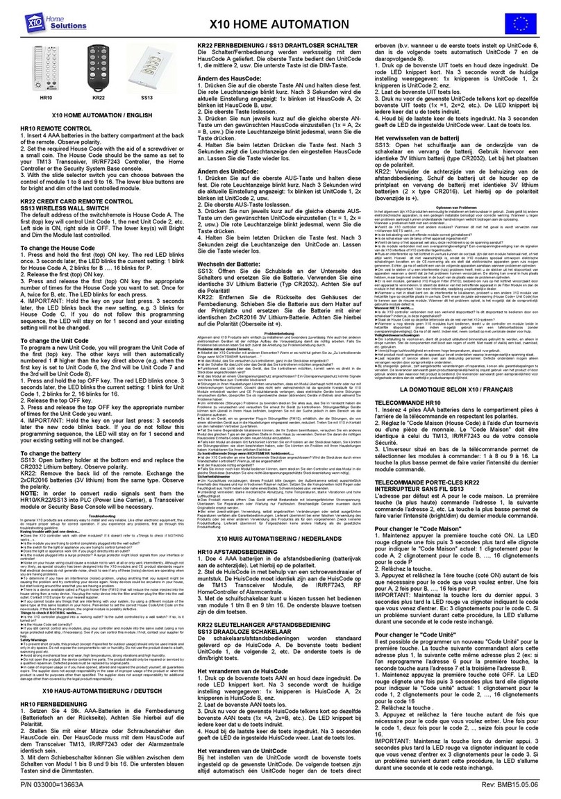
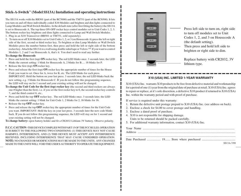
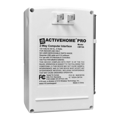
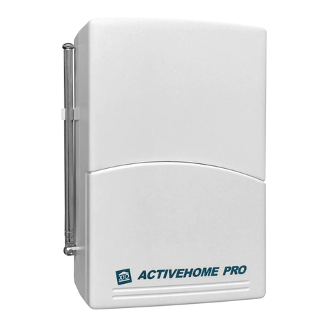
X10 CK11A User manual

OO
OO
OWNERWNER
WNERWNER
WNER’’
’’
’SS
SS
SMM
MM
MANUALANUAL
ANUALANUAL
ANUAL
CK11ACK11A
CK11ACK11A
CK11A
AA
AA
ACTIVECTIVE
CTIVECTIVE
CTIVEHH
HH
HOMEOME
OMEOME
OME
HH
HH
HOMEOME
OMEOME
OME AA
AA
AUTOMAUTOMA
UTOMAUTOMA
UTOMATIONTION
TIONTION
TION SS
SS
SYSTEMYSTEM
YSTEMYSTEM
YSTEM

33
33
3
22
22
2
FCC CFCC C
FCC CFCC C
FCC CAUTIONAUTION
AUTIONAUTION
AUTION
THIS DEVICE COMPLIES WITH PART 15 OF THE FCC RULES.
OPERATION IS SUBJECT TO THE FOLLOWING TWO CONDITIONS:
(1) THIS DEVICE MAY NOT CAUSE HARMFUL INTERFERENCE, AND
(2) THIS DEVICE MUST ACCEPT ANY INTERFERENCE RECEIVED, INCLUDING INTERFERENCE THAT
MAY CAUSE UNDESIRED OPERATION.
This equipment generates and uses radio frequency energy, and if not installed and used properly, that
is, in strict accordance with the manufacturers instructions, it may cause interference to radio and
television reception. It has been type tested and found to comply with the limits for remote control
devices in accordance with the specifications in Sub-Parts B and C of Part 15 of FCC Rules, which are
designed to provide reasonable protection against such interference in a residential installation.
However, there is no guarantee that interference will not occur in a particular installation. If this
equipment does cause interference to radio or television reception, which can be determined by
unplugging the equipment, try to correct the interference by one or more of the following measures.
• Reorient the antenna of the radio/TV experiencing the interference.
• Relocate the interface with respect to the radio/TV.
• Move the interface away from the radio/TV.
• Plug the interface into an outlet on a different electrical circuit from the radio/TV
experiencing the interference.
• If necessary, consult your local Dealer for additional suggestions.
NOTE: Modifications to any of the components in this kit will void the user’s authority to operate this
equipment.
~ R~ R
~ R~ R
~ READEAD
EADEAD
EAD TT
TT
T
HISHIS
HISHIS
HIS FF
FF
F
IRSTIRST
IRSTIRST
IRST! ~! ~
! ~! ~
! ~
RR
RR
READEAD
EADEAD
EAD TT
TT
THISHIS
HISHIS
HIS FF
FF
FIRSTIRST
IRSTIRST
IRST!!
!!
!
SS
SS
SAFETYAFETY
AFETYAFETY
AFETY CC
CC
CONSIDERAONSIDERA
ONSIDERAONSIDERA
ONSIDERATIONSTIONS
TIONSTIONS
TIONS
RemembertoexercisegoodcommonsensewhenusingyourActiveHomehome
automationsystem-especiallywhenschedulingunattendeddevices.Therecanbe
someunexpectedconsequencesifnotusedwithcare.Forexample,anemptycoffee
potcanberemotelyturnedon.Ifthatshould happen,yourcoffee potcouldbe
damagedfromoverheating.Ifanelectricheateristurnedonbyremotecontrolwhile
clothingisdraped overit, afire couldresult.DONOTUSEthesystemforthe controlof
highpowerheatingappliancessuchasportableheaters.
Caution: Toreduce the riskof electric shock, do not disassemble anypart of the Home
Automation System. No user-serviceable parts are inside. If you spill liquid on a unit,
disconnect the unit from the AC outlet to prevent possible fire or shock hazard and consult
authorized service personnel.
Powerline operated equipment or accessories connected to any of these units should bear
the UL listing or CSA certification mark and should not have been modified in any way that
might defeat their safety features.
Warning: Toprevent electric shock hazard, do not expose any partof the Home
AutomationSystem to rain ormoisture.

55
55
5
44
44
4
SETTING THE SLEEP TIMER ....................................................................................... 24
CONTROLLING X10 MODULES................................................................................. 25
TOSET THE X10 SLEEP TIMER .................................................................................. 26
CHANGING THE X10 HOUSE CODE: ........................................................................ 27
CONTROLLING AN IR MINI CONTROLLER..................................................................... 28
AA
AA
ACTIVECTIVE
CTIVECTIVE
CTIVEHH
HH
HOMEOME
OMEOME
OME SS
SS
S
OFTWOFTW
OFTWOFTW
OFTWAREARE
AREARE
ARE
............................................................................................................................................................................
............................................................................................................................................................................
......................................................................................2929
2929
29
INSTALLING ACTIVEHOME SOFTWARE.......................................................................... 30
USING ACTIVEHOME TO CONTROL MODULES ............................................................... 31
SCHEDULES AND MACROS ...................................................................................... 33
OTHER INFORMATION ............................................................................................ 41
SAMPLE FILE ........................................................................................................ 42
ORGANIZING THE ACTIVEHOME DESKTOP ................................................................... 42
HELP AT YOUR FINGERTIPS ....................................................................................... 43
CONFIGURING THE SERIAL PORT ............................................................................... 43
EE
EE
EXPXP
XPXP
XPANDINGANDING
ANDINGANDING
ANDING
YOURYOUR
YOURYOUR
YOUR SS
SS
SYSTEMYSTEM
YSTEMYSTEM
YSTEM
..................................................................................................................................................................
..................................................................................................................................................................
.................................................................................4444
4444
44
TT
TT
TROUBLESHOOTINGROUBLESHOOTING
ROUBLESHOOTINGROUBLESHOOTING
ROUBLESHOOTING
..........................................................................................................................................................................................
..........................................................................................................................................................................................
............................................................................................. 4646
4646
46
WW
WW
WARRANTYARRANTY
ARRANTYARRANTY
ARRANTY
..............................................................................................................................................................................................................
..............................................................................................................................................................................................................
.......................................................................................................4747
4747
47
~ C~ C
~ C~ C
~ CONTENTSONTENTS
ONTENTSONTENTS
ONTENTS ~~
~~
~
CC
CC
CONTENTSONTENTS
ONTENTSONTENTS
ONTENTS
II
II
INTRODUCTIONNTRODUCTION
NTRODUCTIONNTRODUCTION
NTRODUCTION
..........................................................................................................................................................................................................
..........................................................................................................................................................................................................
..................................................................................................... 66
66
6
GG
GG
GETTINGETTING
ETTINGETTING
ETTING SS
SS
S
TT
TT
TARAR
ARAR
ARTEDTED
TEDTED
TED
..................................................................................................................................................................................................
..................................................................................................................................................................................................
................................................................................................. 88
88
8
CONTROLLERS AND MODULES .................................................................................... 8
HOUSE CODES AND UNIT CODES ............................................................................ 10
II
II
INSTNST
NSTNST
NSTALLINGALLING
ALLINGALLING
ALLING
THETHE
THETHE
THE CC
CC
COMPONENTSOMPONENTS
OMPONENTSOMPONENTS
OMPONENTS
............................................................................................................................................................
............................................................................................................................................................
..............................................................................1111
1111
11
TRANSCEIVER MODULE ........................................................................................... 11
LAMP MODULE .................................................................................................... 12
KEYCHAIN REMOTE ............................................................................................... 13
6-IN-1 SUPERREMOTE ............................................................................................ 14
COMPUTER INTERFACE ............................................................................................ 15
SS
SS
SETTINGETTING
ETTINGETTING
ETTING UU
UU
UPP
PP
P
YOURYOUR
YOURYOUR
YOUR SS
SS
SUPERUPER
UPERUPER
UPERRR
RR
REMOTEEMOTE
EMOTEEMOTE
EMOTE
....................................................................................................................................................
....................................................................................................................................................
..........................................................................1616
1616
16
BUTTON DESCRIPTIONS .......................................................................................... 16
SETTING UP FOR TV, VCR, CABLE BOX AND SATELLITE RECEIVER ....................................... 18
USING AUX TO CONTROL ASECOND TV, VCR, CABLE BOX OR SATELLITE RECEIVER .............. 20
SEARCHING FOR CODES ........................................................................................ 22
IDENTIFYING CODES FOUND USING THE SEARCH PROCEDURE ............................................. 23

77
77
7
66
66
6
Usethismanual tobecomefamiliarwithActiveHome...
This manual will briefly explain how your ActiveHome system works and how to set it up.
Next, it will teach you how to control a simple lamp from your PC. Finally, once you’ve
mastered the basics, the manual will show you different automation Macros you can setup
using your ActiveHome software.
~ I~ I
~ I~ I
~ INTRODUCTIONNTRODUCTION
NTRODUCTIONNTRODUCTION
NTRODUCTION ~~
~~
~
II
II
INTRODUCTIONNTRODUCTION
NTRODUCTIONNTRODUCTION
NTRODUCTION
Congratulations on your purchase of the ActiveHome PC based home automation system!
Makeyour lightsandappliances gotowork foryou...
ActiveHome brings added security, convenience and energy savings to your home by
managing your lights and appliances with personalized Macros defined by you.
ActiveHome’seasy-to-usesoftware andhardware can automatealmost any light or
appliancein yourhome. Andit’s easy to install. Within minutes, ActiveHome can make your
lights and appliances go to work for you!
Herearejust someofthethingsyou candowithyourActiveHomeHomeAutomation
System...
• Make your house look “lived-in” by having certain lights or appliances “learn” your
normal living pattern
• Program your lights to come on at dusk (not at a preset time) — so you don’t have to
come home to a dark house.
• Control individual (or groups) of lights or appliances by remote control from any room
in the home.
• Create personalized groups of commands (“Macros”) for certain times of the day, like
when you wake-up or go to bed.

99
99
9
88
88
8
The remotes use radio frequency (RF) signals to send commands to the Transceiver
module. RF signals can go right through walls, so you can use the remotes to control
lights or appliances from anywhere in the home.
With your ActiveHome Home Automation Interface and software, your PC becomes a
very intelligent Controller for all of your home automation tasks.
The ActiveHome Interface connects to your computer’s serial port and then plugs into a
wall outlet. The ActiveHome software tells the Interface what to do. The Interface then
sends digital signals over your existing house wiring to a Module which receives the
signals and executes the command sent by the PC.
~ G~ G
~ G~ G
~ GETTINGETTING
ETTINGETTING
ETTING SS
SS
STT
TT
TARAR
ARAR
ARTEDTED
TEDTED
TED ~~
~~
~
GG
GG
GETTINGETTING
ETTINGETTING
ETTING SS
SS
S
TT
TT
TARAR
ARAR
ARTEDTED
TEDTED
TED
Because we know that you are eager to get started, we’ve kept this introduction as short
as possible, but it contains very valuable information, so you should read through it very
carefully.
CC
CC
CONTROLLERSONTROLLERS
ONTROLLERSONTROLLERS
ONTROLLERS
ANDAND
ANDAND
AND MM
MM
MODULESODULES
ODULESODULES
ODULES
The first thing you need to understand is that there are two different devices you need to
control your house; Controllers and Modules. Any light or appliance that you want to
control is plugged into a Module and that Module is then plugged into a standard AC
outlet.
Modules receive commands from Controllers. Examples include the Lamp Module that
came with this kit. The Transceiver Module also in this kit is another example (although it
also doubles as a controller as described later).
Controllers are also plugged into standard wall outlets and send commands to Modules
over your existing electrical wiring in your house without affecting your electricity in any
way.
The Transceiver Module that came with this kit works as a controller when it is used with a
remote control such as the ones included with this kit. When the Transceiver Module
receives a command from a remote it sends digital signals over your existing house wiring
to a Module which receives the signals and executes the command.

1111
1111
11
1010
1010
10
II
II
INSTNST
NSTNST
NSTALLINGALLING
ALLINGALLING
ALLING
THETHE
THETHE
THE CC
CC
C
OMPONENTSOMPONENTS
OMPONENTSOMPONENTS
OMPONENTS
TT
TT
TRANSCEIVERRANSCEIVER
RANSCEIVERRANSCEIVER
RANSCEIVER MM
MM
MODULEODULE
ODULEODULE
ODULE
The Transceiver Module receives radio frequency (RF) commandsfrom remotes to operate
a lamp or appliance plugged into it. The Transceiver Module also passes on commands
over your house wiring to control other X10 modules. Note that unlike the Lamp Module
you cannot dim and brighten a lamp connected to the Transceiver Module.
You should locate the Transceiver Module centrally in the home for maximum range when
controlled by a remote.
1.1.
1.1.
1. Set the House Code to ‘A’
and the Unit Code slide
switch to 1.
2.2.
2.2.
2. Plug a lamp or appliance
into the Transceiver
Module.
3.3.
3.3.
3. Plug the Transceiver
Module into a convenient
AC outlet. Fully extend
the antenna.
Note:
The slide switch sets the Unit Code for the Transceiver Module’s built-in receptacle
when controlled from a remote or a controller such as the Computer Interface. Set to Unit
Code 1, or Unit Code 9.
HH
HH
HOUSEOUSE
OUSEOUSE
OUSE CC
CC
CODESODES
ODESODES
ODES
ANDAND
ANDAND
AND UU
UU
UNITNIT
NITNIT
NIT CC
CC
CODESODES
ODESODES
ODES
Each Module has a specific address made up of a
House Code (red dial on the face of the Module) and
a Unit Code (black dial on the face of the Module).
The Controller first sends an address and then a
command on the AC power lines. Only the Module
with a matching address will execute the command. If
more than one Module has the same address, both
Modules will execute the command.
Addresses are set on the Module by turning the two
dials on the front of the Module to the desired letter and number (using a small
screwdriver or a coin). The House Code is selected from the letters A through P, and the
Unit Code is selected from the numbers 1 through 16.
~ G~ G
~ G~ G
~ GETTINGETTING
ETTINGETTING
ETTING SS
SS
S
TT
TT
TARAR
ARAR
ARTEDTED
TEDTED
TED ~~
~~
~
UNIT CODE
DIAL
HOUSE CODE
DIAL

1313
1313
13
1212
1212
12
~ I~ I
~ I~ I
~ INSTNST
NSTNST
NSTALLINGALLING
ALLINGALLING
ALLING
THETHE
THETHE
THE CC
CC
COMPONENTSOMPONENTS
OMPONENTSOMPONENTS
OMPONENTS ~~
~~
~
KK
KK
KEYCHAINEYCHAIN
EYCHAINEYCHAIN
EYCHAIN RR
RR
REMOTEEMOTE
EMOTEEMOTE
EMOTE
Use the Keychain Remote to control the Transceiver Module to turn lights on and off. You
can control up to two lights and appliances. The Keychain Remote is very convenient for
switching on entrance lights from your car when you return home in the evening.
After setting up the Keychain Remote as described below, you will be able to use the left
key to control the Transceiver Module and the right key to control the Lamp Module.
1.1.
1.1.
1. Slide off the battery cover
and use a small
screwdriver to set the
code wheel to ‘A’.
2.2.
2.2.
2. Move the slide switch to
position 1-2. 3.3.
3.3.
3. Install two AAA batteries
and refit the battery
cover.
LL
LL
LAMPAMP
AMPAMP
AMP MM
MM
M
ODULEODULE
ODULEODULE
ODULE
The Lamp Module may be used to control any incandescent lamp rated up to 300W. It is
not suitable for other types of lamp such as fluorescent or energy saving lamps, or lamps
which include a dimmer control.
Caution: Do not connect an appliance such as a coffee pot or heater to the Lamp
Module. It may damage the module and the appliance and could cause a fire hazard.
~ I~ I
~ I~ I
~ INSTNST
NSTNST
NSTALLINGALLING
ALLINGALLING
ALLING
THETHE
THETHE
THE CC
CC
COMPONENTSOMPONENTS
OMPONENTSOMPONENTS
OMPONENTS ~~
~~
~
1.1.
1.1.
1. Set the House Code to ‘A’
and the Unit Code to ‘2’. 2.2.
2.2.
2. Plug a lamp into the
Lamp Module. 3.3.
3.3.
3. Plug the Lamp Module
into a convenient AC
outlet.

1515
1515
15
1414
1414
14
~ I~ I
~ I~ I
~ INSTNST
NSTNST
NSTALLINGALLING
ALLINGALLING
ALLING
THETHE
THETHE
THE CC
CC
COMPONENTSOMPONENTS
OMPONENTSOMPONENTS
OMPONENTS ~~
~~
~
CC
CC
COMPUTEROMPUTER
OMPUTEROMPUTER
OMPUTER II
II
INTERFNTERF
NTERFNTERF
NTERFACEACE
ACEACE
ACE
The Computer Interface connects to the serial port of your PC. When you run the
ActiveHome software, timer events, macros and other functions are downloaded to the
interface through the serial cable.
Batteries in the interface keep its clock running if the power fails, so when the power is
restored any timed events are resumed automatically.
Install the interface as follows:
1.1.
1.1.
1. Connect one end of the
interface cable to your
computer.
2.2.
2.2.
2. Plug the other end of the
cable into the Computer
Interface.
3.3.
3.3.
3. Plug the Computer
Interface into a
convenient AC outlet
Continued...
6-6-
6-6-
6-ININ
ININ
IN-1 S-1 S
-1 S-1 S
-1 SUPERUPER
UPERUPER
UPERRR
RR
REMOTEEMOTE
EMOTEEMOTE
EMOTE
The 6-in-1 SuperRemote allows you to control practically everything electrical in your
home. It combines IR technology that lets you control all your TV, VCR, Cable and
Satellite equipment with X10 RF technology that lets you control lamps and appliances
anywhere in your home.
To find out more about configuring the SuperRemote to work with your audio/video
equipment, see the section titled “Setting Up your SuperRemote.”
~ I~ I
~ I~ I
~ INSTNST
NSTNST
NSTALLINGALLING
ALLINGALLING
ALLING
THETHE
THETHE
THE CC
CC
COMPONENTSOMPONENTS
OMPONENTSOMPONENTS
OMPONENTS ~~
~~
~
1.1.
1.1.
1. Push the tab and lift off
the battery cover. 2.2.
2.2.
2. Fit two AAA batteries,
taking care to match the
+ and - marks in the
battery compartment.

1717
1717
17
1616
1616
16
LASTLAST
LASTLAST
LAST
Selects the last channel
viewed on your TV, VCR,
Cable Box or Satellite
Receiver.
CHANNEL +/-CHANNEL +/-
CHANNEL +/-
Works like your original
remote. Also used to switch
X10 modules on and off.
MUTEMUTE
MUTEMUTE
MUTE
Works the same as your
originalremote.
VOLUME +/-VOLUME +/-
VOLUME +/-
Works like your original
remote. Also used to
brighten and dim lamps
connected to X10 Modules.
TIMERTIMER
TIMERTIMER
TIMER
Used to set the Sleep Timer
to automatically switch off
the TV or X10 modules after
a preset time.
CAP (CAPTION)CAP (CAPTION)
CAP (CAPTION)
Hasdifferent function
depending on Mode e.g.
TV Closed Caption in TV
Mode.
PLAPLA
PLAPLA
PLAYY
YY
Y, REW, FF, REW, FF
, REW, FF, REW, FF
, REW, FF, STOP, STOP
, STOP, STOP
, STOP,,
,,
,
PP
PP
PAUSEAUSE
AUSEAUSE
AUSE
Work the same as on your
originalremote.
RECREC
RECREC
REC
Record button. Works the
same as your original
remote. You must press the
REC button twice to begin
recording.
SHIFTSHIFT
SHIFTSHIFT
SHIFT
For accessing additional
functions.
DISP (DISPLADISP (DISPLA
DISP (DISPLAY)Y)
Y)Y)
Y)
Used to access on-screen
information
~ I~ I
~ I~ I
~ INSTNST
NSTNST
NSTALLINGALLING
ALLINGALLING
ALLING
THETHE
THETHE
THE CC
CC
COMPONENTSOMPONENTS
OMPONENTSOMPONENTS
OMPONENTS ~~
~~
~
4.4.
4.4.
4. Plug your computer into
the Computer Interface
(optional).
5.5.
5.5.
5. Slide off the battery cover
and fit 2 AAA batteries in
the battery compartment.
SS
SS
SETTINGETTING
ETTINGETTING
ETTING UU
UU
U
PP
PP
P
YOURYOUR
YOURYOUR
YOUR SS
SS
S
UPERUPER
UPERUPER
UPERRR
RR
REMOTEEMOTE
EMOTEEMOTE
EMOTE
BB
BB
BUTTONUTTON
UTTONUTTON
UTTON DD
DD
DESCRIPTIONSESCRIPTIONS
ESCRIPTIONSESCRIPTIONS
ESCRIPTIONS
INDICAINDICA
INDICAINDICA
INDICATOR LIGHTTOR LIGHT
TOR LIGHTTOR LIGHT
TOR LIGHT
The indicator light flashes
when the remote is
operating.
POWERPOWER
POWERPOWER
POWER
Works in the same way as
your original remote.
SET UPSET UP
SET UPSET UP
SET UP
Usedforprogramming the
remote.
X10X10
X10X10
X10
Lets you control X10
modules to operate lamps
and appliances around
yourhome.
TVTV
TVTV
TV, VCR, CBL, AUX1,, VCR, CBL, AUX1,
, VCR, CBL, AUX1,, VCR, CBL, AUX1,
, VCR, CBL, AUX1,
AUX2, SAAUX2, SA
AUX2, SAAUX2, SA
AUX2, SATT
TT
T
Used to select the device to
control. SAT includes DSS.
0-90-9
0-90-9
0-9
Used as your original
remote and to enter device
codes.

1919
1919
19
1818
1818
18
~ S~ S
~ S~ S
~ SETTINGETTING
ETTINGETTING
ETTING UU
UU
UPP
PP
P
YOURYOUR
YOURYOUR
YOUR UU
UU
UNIVERSALNIVERSAL
NIVERSALNIVERSAL
NIVERSAL RR
RR
REMOTEEMOTE
EMOTEEMOTE
EMOTE ~~
~~
~
Notes:
For audio equipment(CD, stereo etc.) use theAUX1orAUX2button.
Ifyour TV/VCR/Cable Box/Satellite Receiverdoes not respond,trytheothercodesfor
your brand. If it still doesn’t respond, try the Code Search method on page 22.
IftheLED blinked rapidly when you entered the code,youmay haveenteredan
invalid code. Recheck the code in the code list and try again.
If some buttons do not operate your device,try oneoftheothercodesforyourbrand.
SS
SS
SETTINGETTING
ETTINGETTING
ETTING
UPUP
UPUP
UP
FORFOR
FORFOR
FOR TVTV
TVTV
TV, VCR, C, VCR, C
, VCR, C, VCR, C
, VCR, CABLEABLE
ABLEABLE
ABLE BB
BB
BOXOX
OXOX
OX
ANDAND
ANDAND
AND SS
SS
S
AA
AA
ATELLITETELLITE
TELLITETELLITE
TELLITE RR
RR
RECEIVERECEIVER
ECEIVERECEIVER
ECEIVER
~ S~ S
~ S~ S
~ SETTINGETTING
ETTINGETTING
ETTING UU
UU
UPP
PP
P
YOURYOUR
YOURYOUR
YOUR UU
UU
UNIVERSALNIVERSAL
NIVERSALNIVERSAL
NIVERSAL RR
RR
R
EMOTEEMOTE
EMOTEEMOTE
EMOTE ~~
~~
~
1.1.
1.1.
1. Turn on the device you
want to control (TV, VCR,
cable box, satellite
receiver etc.).
2.2.
2.2.
2. Press and hold SETUP
until the LED indicator
lights steadily. Release
the SETUP button.
3.3.
3.3.
3. Press and release mode
button for device you
want to control. The LED
blinks once. Use AUX 1
or 2 for audio equipment.
4.4.
4.4.
4. Enter the 3 digit Code
from the Library Code
Table (separate sheet).
The LED turns off after the
last digit entered.
5.5.
5.5.
5. Point the remote at your
device and press the
POWER button. Your
device should turn off.
6.6.
6.6.
6. Turn your device on and
press CHANNEL +. If the
device responds, setup is
complete.

2121
2121
21
2020
2020
20
4.4.
4.4.
4. Press and release the
mode button that matches
the A/V equipment you
want to control. The LED
blinks once.
5.5.
5.5.
5. Enter the 3 digit Code
from the Library Code
Tables. The LED turns off
after the last digit
entered.
6.6.
6.6.
6. Point the remote at your
audio component and
press the POWER button.
Your audio component
should turn off.
7.7.
7.7.
7. Turn your audio
component on and press
CHANNEL +. If it
responds, setup is
complete.
Notes:
Ifyour audio/videocomponent does notrespond,try
the other codes for your brand. If it still doesn’t respond, try
the Code Search method on page 22.
IftheLEDblinkedrapidlywhenyouenteredthecode,
you may have entered an invalid code. Recheck the code
in the code list and try again.
~ S~ S
~ S~ S
~ SETTINGETTING
ETTINGETTING
ETTING UU
UU
UPP
PP
P
YOURYOUR
YOURYOUR
YOUR UU
UU
UNIVERSALNIVERSAL
NIVERSALNIVERSAL
NIVERSAL RR
RR
REMOTEEMOTE
EMOTEEMOTE
EMOTE ~~
~~
~
UU
UU
USINGSING
SINGSING
SING AUX1AUX1
AUX1AUX1
AUX1 OROR
OROR
OR AUX2AUX2
AUX2AUX2
AUX2 TOTO
TOTO
TO
CONTROLCONTROL
CONTROLCONTROL
CONTROL
AA
AA
ASS
SS
SECONDECOND
ECONDECOND
ECOND TVTV
TVTV
TV, VCR,, VCR,
, VCR,, VCR,
, VCR,
CC
CC
CABLEABLE
ABLEABLE
ABLE BB
BB
BOXOX
OXOX
OX
OROR
OROR
OR SS
SS
SAA
AA
ATELLITETELLITE
TELLITETELLITE
TELLITE RR
RR
RECEIVERECEIVER
ECEIVERECEIVER
ECEIVER
Although the AUX1 and AUX 2 buttons are normally used to control an audio component
such as a CD or stereo system, they can also be configured to control a second TV, VCR,
cable box, or satellite receiver instead.
1.1.
1.1.
1. Turn on the equipment
you want to control. 2.2.
2.2.
2. Press and hold SETUP
until the LED indicator
lights steadily. Release
Setup button.
3.3.
3.3.
3. Press the AUX1 or AUX2
button.
~ S~ S
~ S~ S
~ SETTINGETTING
ETTINGETTING
ETTING UU
UU
UPP
PP
P
YOURYOUR
YOURYOUR
YOUR UU
UU
UNIVERSALNIVERSAL
NIVERSALNIVERSAL
NIVERSAL RR
RR
R
EMOTEEMOTE
EMOTEEMOTE
EMOTE ~~
~~
~

2323
2323
23
2222
2222
22
II
II
IDENTIFYINGDENTIFYING
DENTIFYINGDENTIFYING
DENTIFYING CC
CC
CODESODES
ODESODES
ODES
FOUNDFOUND
FOUNDFOUND
FOUND
USINGUSING
USINGUSING
USING
THETHE
THETHE
THE SS
SS
SEARCHEARCH
EARCHEARCH
EARCH PP
PP
PROCEDUREROCEDURE
ROCEDUREROCEDURE
ROCEDURE
~ S~ S
~ S~ S
~ SETTINGETTING
ETTINGETTING
ETTING UU
UU
UPP
PP
P
YOURYOUR
YOURYOUR
YOUR UU
UU
UNIVERSALNIVERSAL
NIVERSALNIVERSAL
NIVERSAL RR
RR
REMOTEEMOTE
EMOTEEMOTE
EMOTE ~~
~~
~
1.1.
1.1.
1. Press and hold the SETUP
until the LED indicator
lights steadily. Release
Setup button.
2.2.
2.2.
2. Press the mode button
that matches the equip-
ment you want to identify
The LED blinks once.
3.3.
3.3.
3. Press and release SETUP.
The LED blinks once.
4.4.
4.4.
4. To find the first digit,
press each number button
from 0 to 9 until the LED
blinks. The number you
pressed is the first digit of
the code.
5.5.
5.5.
5. Press each number button
from 0 to 9 again as
above to find the second
digit.
6.6.
6.6.
6. Press each number button
in turn to find the third
digit. When the third
digit has been found, the
LED goes out.
SS
SS
SEARCHINGEARCHING
EARCHINGEARCHING
EARCHING FF
FF
FOROR
OROR
OR CC
CC
CODESODES
ODESODES
ODES
1.1.
1.1.
1. Turn on the device you
want to control. 2.2.
2.2.
2. Press and hold SETUP
until the LED indicator
lights steadily. Release
Setup button.
3.3.
3.3.
3. Press the mode button
that matches the equip-
ment you want to control
The LED blinks once.
4.4.
4.4.
4. Press [CHANNEL +]
repeatedly* until the
device to be controlled
changes channel.
If you accidentally go past
the code, press [CHANNEL -]
repeatedly until the channel
changes again.
5.5.
5.5.
5. Press and release the
ENTER button to complete
the setup.
~ S~ S
~ S~ S
~ SETTINGETTING
ETTINGETTING
ETTING UU
UU
UPP
PP
P
YOURYOUR
YOURYOUR
YOUR UU
UU
UNIVERSALNIVERSAL
NIVERSALNIVERSAL
NIVERSAL RR
RR
R
EMOTEEMOTE
EMOTEEMOTE
EMOTE ~~
~~
~
*Note:You may have to press CHANNEL+ many times (50+). If the device does not
have a Channel Up function, use the PLAY button (VCR only) or the POWER button.

2525
2525
25
2424
2424
24
CC
CC
CONTROLLINGONTROLLING
ONTROLLINGONTROLLING
ONTROLLING X10 MX10 M
X10 MX10 M
X10 MODULESODULES
ODULESODULES
ODULES
If you have already installed the Transceiver Module, you can control it and other X10
modules as follows:
1.1.
1.1.
1. Press and release the X10
button. 2.2.
2.2.
2. Use the number buttons
to enter the Unit Code
number of the chosen
module.( You do not
need to enter ‘0’ first for
a single digit number.)
3.3.
3.3.
3. Press the appropriate
button for the function
you require:
On: CHANNEL +
Off: CHANNEL –
Bright: VOLUME +
Dim: VOLUME –
AllLamps On: POWER
All Modules Off: MUTE
Note: You cannot dim or brighten an Appliance Module. If the module was off and you
press its unit code followed by Bright or Dim (VOLUME+ or VOLUME-) this will simply turn
the module on.
~ S~ S
~ S~ S
~ SETTINGETTING
ETTINGETTING
ETTING UU
UU
UPP
PP
P
YOURYOUR
YOURYOUR
YOUR UU
UU
UNIVERSALNIVERSAL
NIVERSALNIVERSAL
NIVERSAL RR
RR
REMOTEEMOTE
EMOTEEMOTE
EMOTE ~~
~~
~
SS
SS
SETTINGETTING
ETTINGETTING
ETTING
THETHE
THETHE
THE SS
SS
S
LEEPLEEP
LEEPLEEP
LEEP TT
TT
T
IMERIMER
IMERIMER
IMER
The Sleep Timer automatically turns off the TV after the time you set (1 to 99 minutes).
Follow the instructions below to set the Sleep Timer:
~ S~ S
~ S~ S
~ SETTINGETTING
ETTINGETTING
ETTING UU
UU
UPP
PP
P
YOURYOUR
YOURYOUR
YOUR UU
UU
UNIVERSALNIVERSAL
NIVERSALNIVERSAL
NIVERSAL RR
RR
R
EMOTEEMOTE
EMOTEEMOTE
EMOTE ~~
~~
~
1.1.
1.1.
1. Press and hold TIMER
until the LED indicator
lights steadily. Release
TIMER button.
2.2.
2.2.
2. Use the number buttons
to enter the sleep time
required (1 to 99
minutes).
3.3.
3.3.
3. Press ENTER to confirm
the setting.
Note: Take care to leave the remote pointing at the TV to ensure it turns off the TV at the
time you set.

2727
2727
27
2626
2626
26
CC
CC
CHANGINGHANGING
HANGINGHANGING
HANGING
THETHE
THETHE
THE X10 HX10 H
X10 HX10 H
X10 HOUSEOUSE
OUSEOUSE
OUSE CC
CC
CODEODE
ODEODE
ODE::
::
:
The SuperRemote defaults to House Code A, and in most cases you will not need to
change this unless you are experiencing interference from a neighboring X10 system.
1.1.
1.1.
1. Press and release the
X10 button. 2.2.
2.2.
2. Press and hold SETUP
until the LED indicator
lights steadily. Release
Setup button.
3.3.
3.3.
3. Use the number buttons to
enter the number
equivalent to the chosen
House Code
(1=A, 2=B ..16=P).
4.4.
4.4.
4. Press the ENTER button to
confirm the House Code.
The LED turns off.
Note:
The House Code you choose must match the House
Code on the Transceiver Module and the ActiveHome
software you are using it with.
~ S~ S
~ S~ S
~ SETTINGETTING
ETTINGETTING
ETTING UU
UU
UPP
PP
P
YOURYOUR
YOURYOUR
YOUR UU
UU
UNIVERSALNIVERSAL
NIVERSALNIVERSAL
NIVERSAL RR
RR
REMOTEEMOTE
EMOTEEMOTE
EMOTE ~~
~~
~
TT
TT
TOO
OO
O
SETSET
SETSET
SET
THETHE
THETHE
THE X10 SX10 S
X10 SX10 S
X10 SLEEPLEEP
LEEPLEEP
LEEP TT
TT
T
IMERIMER
IMERIMER
IMER
The X10 Sleep Timer switches off the chosen modules after the preset time.
1.1.
1.1.
1. Press and release the X10
button. 2.2.
2.2.
2. Press and hold TIMER
until the LED indicator
lights steadily. Release
the TIMER button.
3.3.
3.3.
3. Use the number buttons to
enter the module Unit
Code for the module to
be turned off.
4.4.
4.4.
4. Press the desired function
button (e.g. CHANNEL -
to turn the module off
after the preset time).
6.6.
6.6.
6. Press ENTER to confirm
the setting.
~ S~ S
~ S~ S
~ SETTINGETTING
ETTINGETTING
ETTING UU
UU
UPP
PP
P
YOURYOUR
YOURYOUR
YOUR UU
UU
UNIVERSALNIVERSAL
NIVERSALNIVERSAL
NIVERSAL RR
RR
R
EMOTEEMOTE
EMOTEEMOTE
EMOTE ~~
~~
~
5.5.
5.5.
5. Using the number buttons
enter the sleep time
required (1 to 99 mins).

2929
2929
29
2828
2828
28
AA
AA
A
CTIVECTIVE
CTIVECTIVE
CTIVEHH
HH
HOMEOME
OMEOME
OME SS
SS
SOFTWOFTW
OFTWOFTW
OFTWAREARE
AREARE
ARE
The ActiveHome software lets you:
• Create a graphical representation of your Modules on your computer screen and then
allows you to control your lights and appliances from your computer.
• Create schedules of timed events that automatically run your home 24 hours a day,
7 days a week.
• Define “Macros” that control groups of Modules. For example, a “Coming Home”
Macro might turn on the porch light, the living room light, and the stereo.
A “Goodnight” Macro might turn off all internal lights, turn off the stereo, but leave the
outside security lights on.
• Define schedules that make your home look lived-in when you’re away, by turning
lights, stereos and other appliances on and off at the times you set.
• Create printed reports showing different aspects of your home automation system such
as what Modules are installed in your home, and what timed events have been set.
CC
CC
CONTROLLINGONTROLLING
ONTROLLINGONTROLLING
ONTROLLING
ANAN
ANAN
AN IR MIR M
IR MIR M
IR MINIINI
INIINI
INI CC
CC
CONTROLLERONTROLLER
ONTROLLERONTROLLER
ONTROLLER (IR543)(IR543)
(IR543)(IR543)
(IR543)
If you already own an IR Mini Controller, you will need to change the X10 Home
Automation code in the remote to use it. The code for standard X10 Home Automation is
013. The code to control the IR Mini Controller is 014. To change the code:
1.1.
1.1.
1. Press and hold SETUP
until the LED indicator
lights steadily. Release
the SETUP button.
2.2.
2.2.
2. Press and release the
X10 button. 3.3.
3.3.
3. Enter the 014 to control
an IR Mini Controller,
013 for standard X10
control. The LED turns off
after the last digit
entered.
Note: In most cases, you will not need to use the IR Mini Controller to receive commands
from the remote - the Transceiver Module does this for you and has the added advantage
of working through walls. You can’t control the IR Mini Controller and the Transceiver
Module at the same time.

3131
3131
31
3030
3030
30
UU
UU
USINGSING
SINGSING
SING AA
AA
ACTIVECTIVE
CTIVECTIVE
CTIVEHH
HH
HOMEOME
OMEOME
OME
TOTO
TOTO
TO
CONTROLCONTROL
CONTROLCONTROL
CONTROL MM
MM
MODULESODULES
ODULESODULES
ODULES
The first time you run ActiveHome it will load a file called MYHOUSE.x10. MYHOUSE
will show a graphical representation of a Transceiver Module and a Lamp Module as well
as a sample Macro (more on Macros later). The Transceiver Module has been named “My
Appliance”and the Lamp Module is named “MyLamp Module.”
~ A~ A
~ A~ A
~ ACTIVECTIVE
CTIVECTIVE
CTIVEHH
HH
HOMEOME
OMEOME
OME SS
SS
S
OFTWOFTW
OFTWOFTW
OFTWAREARE
AREARE
ARE ~~
~~
~
II
II
INSTNST
NSTNST
NSTALLINGALLING
ALLINGALLING
ALLING AA
AA
ACTIVECTIVE
CTIVECTIVE
CTIVEHH
HH
HOMEOME
OMEOME
OME SS
SS
SOFTWOFTW
OFTWOFTW
OFTWAREARE
AREARE
ARE
Pleasereadthrough theseinstallation stepscompletely beforeyou startto installyour
ActiveHomesoftware.
1. Make sure your PC is turned on, and you are at the Windows desktop.
2. Insert your ActiveHome CD into your CD-ROM drive.
3. Click on the Start button on your Windows 95/98 desktop.
4. Select Run.
5. Click the Browse button and find your CD ROM drive.
6. Click on the Setup icon
7. Follow the Installer instructions to install your ActiveHome software.
Congratulations! Your software has been successfully installed. If you double click on the
ActiveHome icon you will start the ActiveHome software. A setup pictorial will be
displayed the first time you run the software to remind you how to connect up your
Computer Interface if you haven’t already done so.
~ A~ A
~ A~ A
~ ACTIVECTIVE
CTIVECTIVE
CTIVEHH
HH
HOMEOME
OMEOME
OME SS
SS
SOFTWOFTW
OFTWOFTW
OFTWAREARE
AREARE
ARE ~~
~~
~

3333
3333
33
3232
3232
32
SS
SS
SCHEDULESCHEDULES
CHEDULESCHEDULES
CHEDULES
ANDAND
ANDAND
AND MM
MM
MACROSACROS
ACROSACROS
ACROS
You can schedule each of your Modules to turn on or off any time by clicking on the large
black areas of your “on screen” modules. If you have trouble scheduling modules, check
the on-line help for details on how to schedule events (turning Modules on or off).
You can also define your own automated Macros for the lights and appliances in your
home! Below are some suggested “Macros” that you can create with the Lamp Module
and Appliance Module you installed so far.
SAMPLE MACROS FOR YOU TO TRYSAMPLE MACROS FOR YOU TO TRY
SAMPLE MACROS FOR YOU TO TRY
Included with your ActiveHome software are two Demo Macros. These Macros, “Demo
Macro 1” and “Demo Macro 2”, show up as “on screen” modules also.
Click on the Macro Generator tool bar button (right most button on the tool bar). This will
take you to the Macro Generator screen.
Listed on the right side of the screen are all of the modules that have already been defined
in the ActiveHome software. On the left side of the screen are the “Macros” that have
been defined. Macros are required to have a House Code/Unit Code address (like
modules) along with an On/Off condition to activate the sequence of events called out in
the Macro.
~ A~ A
~ A~ A
~ ACTIVECTIVE
CTIVECTIVE
CTIVEHH
HH
HOMEOME
OMEOME
OME SS
SS
S
OFTWOFTW
OFTWOFTW
OFTWAREARE
AREARE
ARE ~~
~~
~
“My Appliance” is set to address A1 (Housecode A, Unit Code 1 located on the bottom
center of the “on screen” module). This corresponds to the setting of the actual Transceiver
Module that you installed earlier.
You can try out your Transceiver Module now:
1.1.
1.1.
1. Check that you have installed the Transceiver Module, and that the switch on the
appliance connected to it is on.
2.2.
2.2.
2. Click on the switch of “My Appliance”. It takes a second or two to respond.
The “My Lamp Module” on-screen module is set to Housecode A and Unit Code 2, the
same as the actual Lamp Module that you installed earlier.
To try out your Lamp Module:
1.1.
1.1.
1. Check that you have installed the Lamp Module, and that the switch on the lamp
connected to it is on.
2.2.
2.2.
2. Click on the switch of “My Lamp Module”. It takes a second or two to respond.
3.3.
3.3.
3. Click on the slider of “My Lamp Module” and hold down the mouse button while
dragging it to about half way down. When you let go of the button, the lamp dims to
around half brightness. (It may take 1 or 2 seconds to do this).
~ A~ A
~ A~ A
~ ACTIVECTIVE
CTIVECTIVE
CTIVEHH
HH
HOMEOME
OMEOME
OME SS
SS
SOFTWOFTW
OFTWOFTW
OFTWAREARE
AREARE
ARE ~~
~~
~

3535
3535
35
3434
3434
34
The middle module brightens your “My Lamp Module” to full brilliance (100%), but this
happens five minutes AFTER the address of the Demo Macro is detected by the Interface.
Notice the clock face on the linked modules. The middle module clock face is showing
clock hands. This is an indication that a time delay has been set. To look at a delay time
or to set a time delay, double click on the clock.
The next linked module is your “My Appliance” module and it is set to turn off ten minutes
after address A3-On is detected. The last module is your “My Lamp Module” again, this
timeit is turning off fifteenminutes after A3-On is detected.
Insummary, what Macro A3-On does is:
• Turn on “My Lamp Module” immediately at 50% brightness
• Turn on “My Appliance” module immediately
• Brighten the same “My Lamp Module” to 100% brightness after 5 minutes
• Turn off the same “My Appliance” module after 10 minutes
• Turn off the same “My Lamp Module” after 15 minutes
You can try running this Macro by selecting Macro from the menu bar and then Exit and
Download.Then, clickthe button on the Macro module named Demo Macro 1. This Macro
will take 15 minutes to complete because of the delay times we used.
~ A~ A
~ A~ A
~ ACTIVECTIVE
CTIVECTIVE
CTIVEHH
HH
HOMEOME
OMEOME
OME SS
SS
S
OFTWOFTW
OFTWOFTW
OFTWAREARE
AREARE
ARE ~~
~~
~
“Demo Macro 1,” with a Housecode/Unit Code address of A3-On, on the left side of
the screen, has five modules “linked” together. If you look closely, you will see that there
are really only two different modules, “My Lamp Module” and “My Appliance” module.
Each of the five modules are doing something slightly different. The top module turns on
My Lamp Module at 50% brightness whenever the Interface detects an A3-On address
(the address of the Demo Macro) being sent over your house wiring. The next module
turns on your “My Appliance” module at the same time as “My Lamp Module” turns on at
50% brightness.
~ A~ A
~ A~ A
~ ACTIVECTIVE
CTIVECTIVE
CTIVEHH
HH
HOMEOME
OMEOME
OME SS
SS
SOFTWOFTW
OFTWOFTW
OFTWAREARE
AREARE
ARE ~~
~~
~

3737
3737
37
3636
3636
36
OK, how do we set all this up? First take the physical Lamp Module (address A2) that we
used previously, to your bedroom and connect your bedside lamp to it. Be sure to turn the
lamp on. Take the Transceiver Module (address A1) to your kitchen and connect your
coffeepot to it (remember to turn it on).
Now let’s rename the on screen “My Lamp Module” by clicking on the name field, press
backspace, then type Bedside Lamp and push enter. Also change the name of your “My
Appliance” module to Coffee Pot.
Next, go to the Macro Generator screen (click the right most button on the tool bar) and
click Macro on the menu bar. A pull down menu will appear, click on Fast Macro. A new
Fast Macro will be created for you named “Macro 1” with an address of A4-On. The
ActiveHome software always defaults to the next available Housecode/Unit Code address
when creating a new module or Macro. The software will also provide the next on/off
switch state for that address. To change the on/off state, click on the on/off field.
To define your Macro:
1. Change the name of the Macro to WAKE UP.
2. Move your cursor over to the right side of the screen, with the left mouse button click
on the “Bedside Lamp” module and drag it to the left side of the screen and drop it on
top of the WAKE UP Macro. A copy of the “Bedside Lamp” will automatically link to
the Wake UP Macro. “Bedside Lamp” is already turned on for you, so we do not need
to do anything else with it.
~ A~ A
~ A~ A
~ ACTIVECTIVE
CTIVECTIVE
CTIVEHH
HH
HOMEOME
OMEOME
OME SS
SS
S
OFTWOFTW
OFTWOFTW
OFTWAREARE
AREARE
ARE ~~
~~
~
Note: If your computer has Rapid Resume, Wake Up on Ring, Instant On, On Now, or
something similar, you should enable this feature to take full advantage of ActiveHome’s
capabilities. Refer to the on-line Help for more details.
A second Demo Macro, with a Housecode/Unit Code address of A3-Off, shown on the
left side of the Macro Generator screen, has two modules “linked” together. Macro A3-Off
is shown to demonstrate that you can have both an On and an Off Macro, which can be
totally unrelated, for each House Code/Unit code address. Because a Macro initiates a
sequence of events (which could be turning devices on or off), we can have the turn ON
commandfor a given address toinitiate a Macro and theturn OFF command for that same
address to initiate a completely different Macro.
CREACREA
CREACREA
CREATING YOUR OWN MACROTING YOUR OWN MACRO
TING YOUR OWN MACROTING YOUR OWN MACRO
TING YOUR OWN MACRO
Let’s see if we can put what we learned from the Demo Macro to actual use in your
home...
Let’s define a Wake-Up in the morning Macro. What do you want to do when you wake up
inthe morning?Let’s assume you want to turn on the lampnext toyour bed.You also want
to turn on the coffee pot in the kitchen so you have fresh coffee for breakfast. When you
getout of the bathroom you can turn off the lamp and head tothe kitchen for that cup of
coffee. Don’t forget, you need to turn off the coffee pot before you leave for work.
~ A~ A
~ A~ A
~ ACTIVECTIVE
CTIVECTIVE
CTIVEHH
HH
HOMEOME
OMEOME
OME SS
SS
SOFTWOFTW
OFTWOFTW
OFTWAREARE
AREARE
ARE ~~
~~
~

3939
3939
39
3838
3838
38
~ A~ A
~ A~ A
~ ACTIVECTIVE
CTIVECTIVE
CTIVEHH
HH
HOMEOME
OMEOME
OME SS
SS
S
OFTWOFTW
OFTWOFTW
OFTWAREARE
AREARE
ARE ~~
~~
~
The top bar on the Timer Settings screen is where you set the execution time. Drag the
green cursor, on the top, to set the desired time, or type the time into the box in the top
right hand corner (in this format, 12:00AM or 08:30PM). Note, you can’t set OFF times
for Macros, because you are setting the time that the Macro will execute not what it is
supposed to do.
Next, click on the day or days that you want the Macro to execute. You can select Today,
Tomorrow, Weekdays, Weekends, Every day. Or just click on the particular day or days
you want. You can set the Macro to happen at Dusk or Dawn instead of at a specific time.
You can also select Specific Dates. Doing so will increase the size of the window to show
you a range of dates. Select the range of dates that you want these timed events to occur
between.
3. Drag and drop a copy of “Coffee Pot” over to the WAKE UP Macro. Coffee Pot will
now be linked to your WAKE UP Macro. “Coffee Pot” is already turned on for you,
so we do not need to do anything else with this either.
4. Drag and drop the Bedside Lamp module to the left side of the screen again, notice
that this time the Time Delay Screen is automatically shown, click and drag the pointer
to 5 minutes, click on OK.
5. This time set the brightness to Dim the lamp to zero.
6. Finish by dragging over the Coffee Pot to the left side of the screen again, this time
set the time delay to one hour and click its switch to set it to turn off.
Select Macro on the menu bar, then click on Exit and Download. The Macro you just
created will then be initialized and downloaded to the Interface. You will be returned to
the ActiveHome main screen. Notice that you now have a new “on screen” Macro module
named WAKE UP.
Next, you need to schedule your Macro to execute at a specific time by clicking in the
“Control Time” window (big black rectangle) of the Macro module, which takes you to the
Timer Settings screen where you can program the execution times for your Macro.
~ A~ A
~ A~ A
~ ACTIVECTIVE
CTIVECTIVE
CTIVEHH
HH
HOMEOME
OMEOME
OME SS
SS
SOFTWOFTW
OFTWOFTW
OFTWAREARE
AREARE
ARE ~~
~~
~
Other manuals for CK11A
1
Table of contents
Other X10 Home Automation manuals

X10
X10 CM15A User manual

X10
X10 HK10A SUPERREMOTE User manual

X10
X10 Stick-A-Switch Model SS15A User manual

X10
X10 RR501 User manual

X10
X10 Mini Controller User manual

X10
X10 UM506 User manual

X10
X10 KR22A User manual

X10
X10 HR10 User manual

X10
X10 Stick-A-Switch Model SS13A User manual

X10
X10 CM15 User manual
Popular Home Automation manuals by other brands

IDS
IDS Core Smart Home Gateway V1 operating manual

TP-Link
TP-Link HS110 quick start guide

Lutron Electronics
Lutron Electronics Caseta Diva Smart Dimmer quick start guide

inohom
inohom Smart Touch Switch 1 user manual

TKB Home
TKB Home TZ69 quick start guide

Aqara
Aqara Smart Home Starter Kit quick start guide