V1.2 Page 3of 14 www.xeryon.com
1. General notes
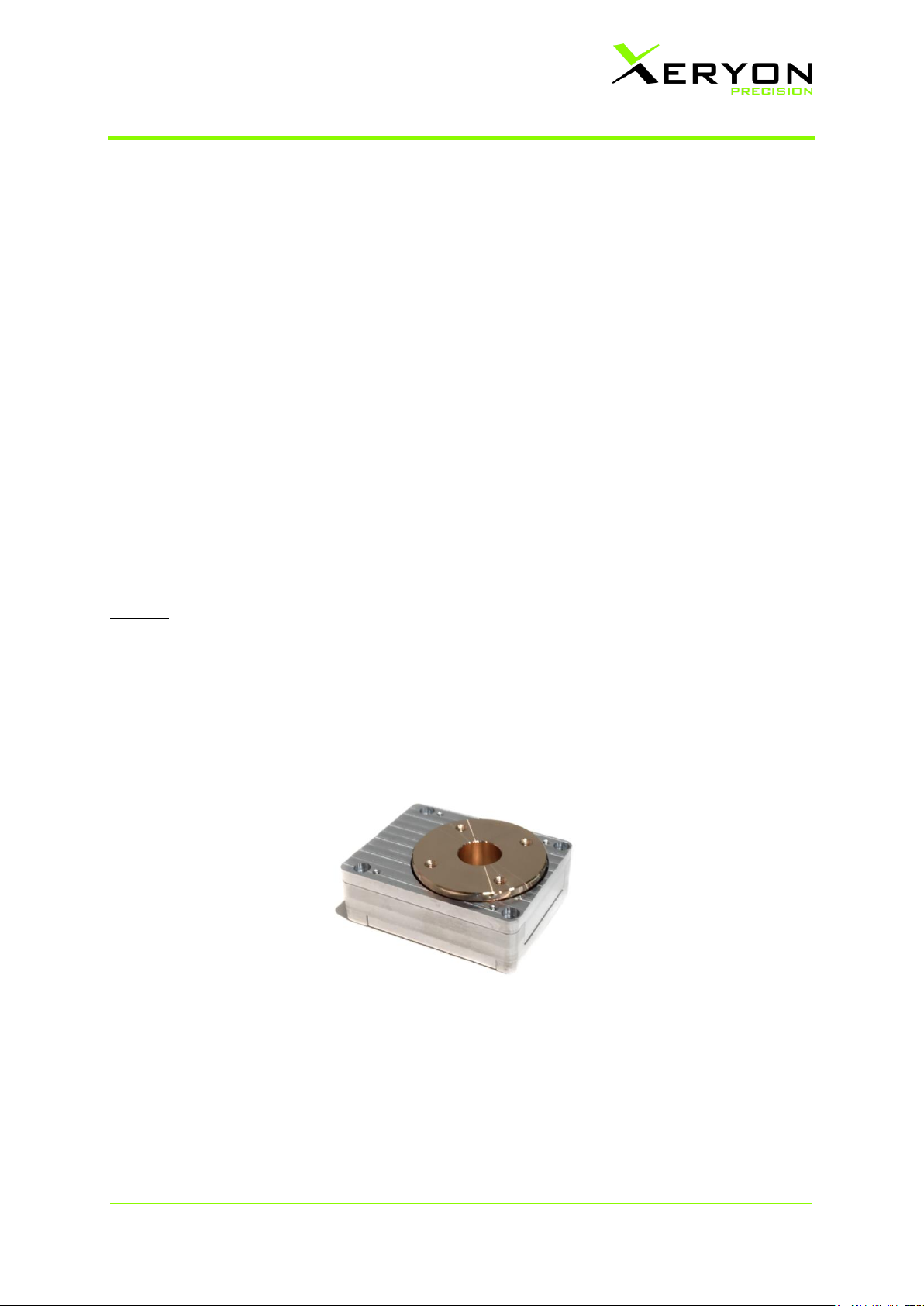
Important
Before using the XRT-A for the first time, please read this manual carefully. This manual contains
additional information on handling and care. Do not apply more than 1 N force on the rotor as this
can lead to a damaged stage.
Cleaning
Do not use any unsuitable cleaning agents, chemicals, grease/oil or techniques for cleaning. This
could damage the surfaces and products could be contaminated by abraded particles. For vacuum
and cleanroom applications, gloves are required to avoid contamination of the device during
unpacking and installing the device.
Servicing
Repairs may only be carried out by Xeryon’s trained service technicians. Only original Xeryon’s
spare parts may be used.
Authorised personnel
Please ensure that the XRT-A is installed and operated by authorized and trained personnel. All
operators must have read and understood this user manual, and in particular the safety regulations.
Place of use
Avoid large temperature fluctuations, vibrations and shocks. These conditions can distort
measurements and can even lead to a damaged stage.
Humidity and dust
Keep relative humidity limited to max. 80%. A higher relative humidity will damage the piezos inside
the stage. Keep the stage away from dust. Excessive dust may affect the integrated bearings.
Storage and transport
Use the original packaging for shipping or transporting the XRT-A. In order to prevent damage from
vibrations and shocks, pack and lock all moving parts (according to this manual) in their original
packaging and ship it appropriately. Store and transport the XRT-A in a closed container or plastic bag,
free of dust and humidity. Add desiccant bag in closed container. Avoid excessive vibrations during
transport. Storage temperature: 0 to +40 °C.
Environment & health
The external surfaces of the device do not contain hazardous materials for human health or the
environment. Inside the device however, PZT is present. The electronics are RoHs compatible.
Do not throw in the garbage bin. Dispose of in a responsible matter, according to local legal regulations