XIEGU G90 User manual

Document No.:
Short-Wave Transceiver Series
Maintenance Manual
XIEGU
Classification Level:
Confidential
G90/G90S
Version: First Edition
Private and Confidential!
Revision: 0
Revision Date: July 27, 2022

XIEGU Product Maintenance Manual G90/G90S Portable Short-Wave Transceiver
XIEGU All Rights Reserved Version No.: 1.0 2022-07 Page 2of 48
Contents

I. Overview of the Whole Device
G90/G90S is a short-wave transceiver with ZIF zero-IF structure, built-in automatic antenna tuner, and
a transmitting power of 20W.
The block diagram of each part of the whole device is as follows:
Small signal board unit:

XIEGU Product Maintenance Manual G90/G90S Portable Short-Wave Transceiver
XIEGU All Rights Reserved Version No.: 1.0 2022-07 Page 4of 48
Display unit:

XIEGU Product Maintenance Manual G90/G90S Portable Short-Wave Transceiver
XIEGU All Rights Reserved Version No.: 1.0 2022-07 Page 5of 48
Base board unit:
Basic skills of board-level maintenance:
1. Be familiar with the circuit structure of the whole device and accurately grasp its signal flow.
2. Be familiar with the status of each working voltage and be able to measure it accurately.
3. Be able to operate the radio proficiently and combine various operations to support the maintenance
process.
4. Be familiar with the meaning of each physical quantity and use it in combination with the actual
situation of the overhauled product.
5. Be able to skillfully use and set commonly used measuring instruments and meters.

XIEGU Product Maintenance Manual G90/G90S Portable Short-Wave Transceiver
XIEGU All Rights Reserved Version No.: 1.0 2022-07 Page 6of 48
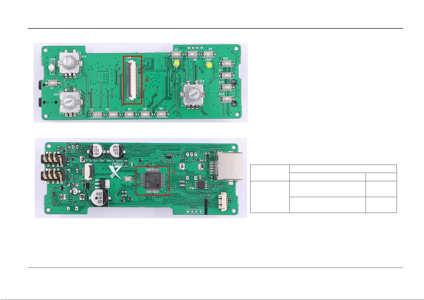
The head of G90 can be separated from its body, with hot swap supported. Therefore, in the
maintenance process, this feature can be utilized to quickly locate whether the fault point is in the
main unit or the head unit.
The heads ofdifferent versions can be interchanged, andthe replacement method can be taken to
quickly locate whether it is the fault of the head.
Main troubleshooting methods:
Check according to the signal flow direction: Check step by step along the signal flow to find
abnormalities.
Judge based on voltage/ current: According to the measured voltage or current, quickly and
roughly judge whether the product has a short circuit/ open circuit. Take full advantage of thermal
imager to troubleshoot short-circuit points.
Component-level inspection: Perform fault inspection according to the inherent characteristics
of components.
To sum up, the maintenance personnel need to have a comprehensive understanding of the overall
structure, signal flow, unit function, and operation method of the product, and at the same time arm
themselves with certain basic knowledge of module and circuit.

XIEGU Product Maintenance Manual G90/G90S Portable Short-Wave Transceiver
XIEGU All Rights Reserved Version No.: 1.0 2022-07 Page 7of 48
Next, each circuit board will be regarded as a unit to explain the judgment, detection and maintenance
of faults by categories in combination with common fault phenomena.
Some fault phenomena have appeared to be the same on the single board and the whole device.
Therefore, the maintenance method of the same fault on the single board and the whole device will be
explained at the same time.
II. Board-Level Maintenance
2.1 Display
Fault phenomenon: The indicator light does not light up
Fault
Phenomenon
Maintenance Method
Display
Whole device
The LED light
does not light up
Check its welding
direction
/
Fault
Phenomenon
Maintenance Method
Display
Location
The bicolor
LED light does
not light up
Check whether the two
resistors on the back
are faultily welded
Checkpoint 1
Fault phenomenon: The display is blank
Checkpoint 1

XIEGU Product Maintenance Manual G90/G90S Portable Short-Wave Transceiver
XIEGU All Rights Reserved Version No.: 1.0 2022-07 Page 8of 48
Fault
Phenomenon
Maintenance Method
Display
Checkpoint
Blank display
Check whether the FPC
pedestal is faultily welded
A
Check whether there is any false
welding at the MCU pins B
This fault is mostly caused by the false welding of components.
During repair welding of the FPC pedestal, it is necessary to
shorten the welding time as much as possible to avoid thermal
deformation of the pedestal.

XIEGU Product Maintenance Manual G90/G90S Portable Short-Wave Transceiver
XIEGU All Rights Reserved Version No.: 1.0 2022-07 Page 9of 48
Fault phenomenon: It cannot be written into Bootloader or the application
Fault phenomenon: high current
Fault
Phenomenon
Maintenance Method
Display
Checkpoint
Failure to burn
program
Check whether the voltage
is 3.3V
C
Check whether the MCU is
faultily welded B
Check whether the pedestal
is faultily welded
D
Fault
Phenomenon
Maintenance Method
Display
Checkpoint
High current and
hot MCU
Check whether the voltage
is 3.3V C
If the voltage at point C > 3.3V, the LDO regulator has already
been damaged. It is necessary to replace the LM1117-3.3
regulator first, confirm that the output voltage is 3.3V, and then
replace the damaged MCU. Otherwise, it will cause a secondary
fault to burn the MCU.
During the maintenance, it has ever been found that the short
circuit of the display FPC pedestal welding lead to the 3.3V
grounding short circuit, where attention to check is thus required.

XIEGU Product Maintenance Manual G90/G90S Portable Short-Wave Transceiver
XIEGU All Rights Reserved Version No.: 1.0 2022-07 Page 10 of 48
Fault phenomenon: no power for the hand microphone input, no action after hand microphone
buttons are pressed, and no backlight at the hand microphone
Fault phenomenon: The top button does not respond when it is pressed
Fault
Phenomenon
Maintenance Method
Display
Checking
Area
The hand
microphone
does not
respond
Check whether the
components in this area are
faultily welded
E
Check whether the elastic contacts in the RJ45 pedestal are in
good condition, and whether there is deformation or dislocation.
Fault
Phenomenon
Maintenance Method
Display
Checkpoint
The top button
does not respond
when it is pressed
Check whether the socket
pins are faultily welded F
Check whether the components on the top button board are
faultily welded.
Check whether the connecting lines are in good contact and the
line sequence correct.

XIEGU Product Maintenance Manual G90/G90S Portable Short-Wave Transceiver
XIEGU All Rights Reserved Version No.: 1.0 2022-07 Page 11 of 48
Fault phenomenon: The device head cannot communicate with the host, and the screen displays
COMM LOST
Fault phenomenon: The starting-up speed is too fast, and it enters the main interface as soon as it
flashes/ cannot enter the flashing state
Fault
Phenomenon
Maintenance Method
Display
Checkpoint
No
communication
between the
device head
and the host
Check whether the MCU pins
are faultily welded and whether
the chip is damaged
B
Check whether the ESD diode
is broken down
G
In addition, note to check whether the DB9 connection board is
faultily welded.
Fault
Phenomenon
Maintenance Method
Display
Checkpoint
Fast starting-up
speed/ failure
to enter the
flashing state
Check whether the two pins of
all buttons are short-circuited by
themselves
Button
Check whether there is
grounding short circuit of all
encoder pins
Encoder
Encoder
Button
Encoder
Button

XIEGU Product Maintenance Manual G90/G90S Portable Short-Wave Transceiver
XIEGU All Rights Reserved Version No.: 1.0 2022-07 Page 12 of 48
Fault phenomenon: The encoder does not respond when it is pressed
Fault phenomenon: A certain button does not respond when it is pressed
Fault Phenomenon
Maintenance Method
Display
Checkpoint
The encoder does
not respond when it
is pressed
Check whether the encoder
switch pins are faultily
welded or there is any
grounding short circuit
H.J.K
Also pay attention to whether the other three pins of the encoder
are short-circuited by lap welding of adjacent pins.
Some of these fault points are very subtle, such as PCB
disconnection, or rubbing of the solder mask on the PCB by the
metal fixing pins of the encoder, resulting in a grounding short
circuit of the pin wiring.
Fault
Phenomenon
Maintenance Method
Display Checkpoint
A certain button
does not respond
when it is pressed
Check whether the two pins
are connected after the button
is pressed
Fault button
Check with power off.
Some of these fault points are very subtle, such as PCB
disconnection, or rubbing of the solder mask on the PCB by the
metal of the button casing, resulting in a grounding short circuit.
Button
Button

XIEGU Product Maintenance Manual G90/G90S Portable Short-Wave Transceiver
XIEGU All Rights Reserved Version No.: 1.0 2022-07 Page 13 of 48
2.2 Small Signal Board
At present, there are mainly two versions of small signal boards with large production volume, i.e.
G90-SSIGBD-V2.0.7-GAI03 and the current version G90-SSIGBD-V2.1.1. The old version is the
same as the current version in terms of principle, with only part of circuit units having been changed.
This manual is to explain in accordance with version V2.1.1.
The distribution of each unit of the small signal board is shown in the following diagram:
Receiving
mixing
Transmitting
mixing
Audio amplifier unit
Earphone/ horn switch
Baseband unit
Local oscillator unit
Main MCU
BPF unit
External
interface

XIEGU Product Maintenance Manual G90/G90S Portable Short-Wave Transceiver
XIEGU All Rights Reserved Version No.: 1.0 2022-07 Page 14 of 48
The general parameters of each basic measurement point on the small signal board are as follows:
Maintenance methods:
We are to explain with the default test frequency point of
14.270MHz as an example. The maintenance test frequency point
of each subsequent step is considered to be 14.270MHz by
default.
Measurement
Point
Voltage V Name
N0.94~0.98
Audio unit reference voltage
Vref
M3.3
Local oscillator unit power
supply
Q
3.3
Baseband unit power supply
S
3.3
MCU power supply
T
+9
Public 9V power supply
U
+9T
Transmitting 9V power supply
V
+9R
Receiving 9V power supply
W
+5
Public 9V power supply
+9T is only available in the transmitting state, and it is
theoretically 0V when receiving.
+9R is 0V in the transmitting state.
+9, +5, and each 3.3V voltage are available in both the receiving
state and the transmitting state.
Measurement
Point
Frequency
MHz
Amplitude
Vpp
Name
X
12.288
3.9
CODEC clock
P26.000 3.6
TXCO
reference clock
L14.270 5.9
Local oscillator
output
R8.000 1.94
MCU clock
frequency
The local oscillator outputs two signals respectively, and their
frequencies are the same, both of which are the currently set
receiving and transmitting frequencies.

XIEGU Product Maintenance Manual G90/G90S Portable Short-Wave Transceiver
XIEGU All Rights Reserved Version No.: 1.0 2022-07 Page 15 of 48
Fault phenomenon: It cannot be written into Bootloader or the application
Fault
Phenomenon
Maintenance Method
Small signal board
Checkpoint
Inability to
burn or start up
the application
1. Check whether the 3.3V
power supply is normal
A1
2. Check whether the main
MCU pins are faultily welded A2
3. Check whether the COMM
socket is connected with the
main MCU pin
A3
Pay attention to the damage of COMM socket, such as short
circuit, open circuit, etc. Measure whether the relevant leads from
A3 to A2 are connected through the on-off position of the
multimeter.

XIEGU Product Maintenance Manual G90/G90S Portable Short-Wave Transceiver
XIEGU All Rights Reserved Version No.: 1.0 2022-07 Page 16 of 48
Fault phenomenon: receive failure (or no signal tone)
Maintenance methods:
1. First, check whether the local oscillator on the small signal board
works normally.
Instrument settings:
Name
Setting Parameters
Parameter 1 Parameter 2
Parameter
3
Signal Source Frequency:
14.271MHz
Amplitude:
-20dBm
/
Oscilloscope Time base: 50ns
Y-axis:
100mV
X10 gear
Note: The oscilloscope shall be set at X10 gear, and the test probe
shall also be set at X10 gear. Coupling mode:AC coupling.
2. First measure the working condition of local oscillator, and the test
data shall be roughly as follows:
Checkpoint
Frequency
MHz
Amplitude
Vpp
Name
A1 26.000 3.6
TXCO reference
clock
A2 14.27 5.9
Local oscillator
output
The upper end of the two resistors at A2 checkpoint is for the
quadrature output of the local oscillator signal, with the same
frequency and amplitude.
3. Connect the output signal of the signal source to the small signal
board, and measure the signal strength of checkpoints A3 and A4
respectively in turn. Normally, it shall be as follows:
Checkpoint
Frequency MHz
Amplitude mVpp
A3
14.271
80
A4
14.271
380
During the above test, PRE shall be turned on.
4. Measure the signal strength of checkpoint A5 as follows: (signal
source output: -40dBm)
Name
Setting Parameters
Parameter 1
Parameter 2
Parameter 3
Oscilloscope
Time base:
1ms
Y-axis:
100mV
X10 gear

XIEGU Product Maintenance Manual G90/G90S Portable Short-Wave Transceiver
XIEGU All Rights Reserved Version No.: 1.0 2022-07 Page 17 of 48
Checkpoint Frequency
Amplitude
mVpp
Name
A5 1kHz 350
Baseband
signal
The frequency measured at the two test points at checkpoint A5 shall be 1kHz, and amplitude is
basically the same (the allowable difference is within 10mV).
5. After measuring according to the sequence of each checkpoint in the above steps, if the value
measured at a checkpoint is not consistent with the standard value, it indicates that there may be a
fault.
6. If no signal is measured when measuring checkpointA3, directly measure whether there is an input
signal on the terminal of the antenna pedestal:
If signals can be measured at the antenna pedestal, while cannot be measured at the checkpoint
A3, it indicates that there may be an open circuit fault in the IPX signal line for receiving, or there
may be a short circuit in the outlet socket for received signal of the base board.
If signals cannot be measured at the antenna pedestal and the checkpoint A3, it indicates that
there may be a short circuit fault in the IPX signal line for receiving, or there may be a short
circuit in the outlet socket for received signal of the base board.
Treatment: Check whether the socket for receiving signal is short-circuited, replace with a new IPX
signal line, and test again.
If signals can be measured at the antenna pedestal while cannot be measured at the lower end of
the antenna-coupling capacitor, it is likely that the antenna pedestal lead is poorly welded to the
base board, or the pad of the base board falls off, or the antenna-coupling capacitor is faultily
welded
7. If there is a signal at the checkpoint A3 while no signal at the checkpoint A4, it is related to the
failure of the BPF unit. The troubleshooting of such faults is explained in the following chapter of BPF
fault.
8. When setting the volume at about 80%, a sine wave signal shall be measured at the checkpoint A6 at
the output terminal (PIN-5) of LM386:
Checkpoint
Receiving Frequency
MHz
Amplitude
Vpp
Frequency
Signal
A6 14.270 1.95
1kHz
Relatively standard sine
wave
Special reasons for some "Receive Failures":
The IPX line for receiving is damaged.
The RX signal base next to checkpoint A3 is welded reversely in direction.
The gas discharge tube on the left side of checkpoint A3 is broken down.
Antenna
Coupling
capacitor
Outlet socket
for received
signal

XIEGU Product Maintenance Manual G90/G90S Portable Short-Wave Transceiver
XIEGU All Rights Reserved Version No.: 1.0 2022-07 Page 18 of 48
Fault phenomenon: BPF unit test fault (there is no amplitude-frequency curve in network
analysis test)
Maintenance methods:
1. First check the band switching control area on the back of the small
signal board:
Fault
Phenomenon
Maintenance Method
Small signal board
Checking
Area
No BPF
Whether there is false welding in the
switching control area
A8
2. Set the instrument:
Name
Setting Parameters
Parameter 1
Parameter 2
Parameter 3
Signal Source Frequency:
14.271MHz
Amplitude:
-20dBm
/
Oscilloscope Time base: 50ns
Y-axis:
100mV
X10 gear
Then check whether the signal amplitude of checkpoints A3, A6, A7,
A4 is normal in turn.
Area A6 collects the input of each segment of BPF;
Area A7 collects the output of each segment of BPF;
When PRE is turned on, the measured data at each checkpoint shall be
as follows:
Checkpoint
Frequency
MHz
Amplitude
mVpp
Name
A3
14.271
80
A6 14.271 80
Input of each segment
of BPF
A7 14.271 50
Output of each segment
of BPF
A4
14.271
380
Receive mixer input
3. After selecting a certain segment of BPF, the positive pressure
differential between the input and output switching diodes of this
segment of BPF shall be about 0.7 ~ 0.9V. If the selected BPF
switching diode has a reverse pressure differential, it indicates that the
gating of this segment is faulty.
4. The fault point of BPF unit can be found out according to the above
steps.
The damaged inductance and capacitance in BPF will also cause
faults, so pay attention to that.

XIEGU Product Maintenance Manual G90/G90S Portable Short-Wave Transceiver
XIEGU All Rights Reserved Version No.: 1.0 2022-07 Page 19 of 48
Fault phenomenon: startup failure, unable to connect with the machine head (mainboard MCU
indicator light flashes slowly and is always on)
Maintenance methods:
The main manifestations of such faults are as follows:
After starting up, the blue indicator light beside the main MCU
flashes slowly or is always on.
After starting up, the level on the machine head display is
-256dBm, and there is no waterfall plot.
Maintenance methods:
Fault
Phenomenon
Maintenance Method
Small signal board
Checkpoint
Startup failure
Check whether there is false
welding of components
IC1
Check whether there is false
welding of components
IC2
Check whether there is false
welding of components
IC3
Check whether there is false
welding of components
IC4
Check whether there is false
welding of components
A10
Check whether the two diodes
are broken down
A11
According to previous maintenance experience, there is a higher
chance of false welding of IC3, which shall be checked
emphatically.
Principle: IC1, IC2, IC3 and IC4 are for IIC bus communication.
When there is a problem in the bus communication of a chip, the
communication mechanism will give up the correspondence with
it after a certain time and change to communicate with other
remaining chips. The phenomenon when such actions occur:
After starting up, the indicator light is always on, and then
starts flashing after about 10 seconds. At the same time, the
sound of relay operation is heard, and background noise of
the horn starts.
Special attention:
There is a higher defect rate of domestic GD32F450 series chips
(about 4%), causing a lot of failures such as startup failure or
connection failure with the machine head.

XIEGU Product Maintenance Manual G90/G90S Portable Short-Wave Transceiver
XIEGU All Rights Reserved Version No.: 1.0 2022-07 Page 20 of 48
Fault phenomenon: no PRE function (after turning on PRE, the amplitude-frequency curve of
network analysis does not rise)
Maintenance methods:
The fault phenomena are as follows:
During the network analysis test, turn on/ off the PRE function, and the
amplitude of the amplitude-frequency curve will not change (or
become low)
Maintenance methods:
The instrument settings are as follows:
Name
Setting Parameters
Parameter 1 Parameter 2
Parameter
3
Signal Source
Frequency:
14.271MHz
Amplitude:
-20dBm /
Oscilloscope Time base: 50ns
Y-axis:
100mV
X10 gear
After PRE is turned on, the measured data at each checkpoint shall be
as follows:
Checkpoint
Frequency
MHz
Amplitude
mVpp
Name
A12
14.271
50
Amplifier input
A14 14.271 680
Amplifier
output
If there is a great difference between the measured signal amplitude
and the standard data in the table, the following measurements are
required:
Checkpoint
Voltage
Voltage difference between base (B)
and emitter (E) of amplifier triode
About 0.55 ~ 0.7V
A13
4.5
~
5V
At the same time, check whether the PRE control signal
"#PRE_EN" and AS179 controlled voltage turn normally.
PRE circuit unit
Other manuals for G90
10
This manual suits for next models
1
Table of contents
Other XIEGU Transceiver manuals