XIEGU X5105 User manual

XIEGU
X5105
HF/50MHZ Portable Short-wave Transceiver
Operation Manual
V3.0 Preview Edition

Content
1
2
3
6
Basic characteristics
Panel keys
Left interface
Right interface
7
8
9
10
12
Handheld microphone function
Description for external interfaces
Charging and maintenance of build-in battery
Connection of external power supplies
Menu operation
14
15
17
34
35
36
37
38
39
40
41
42
43
44
45
47
Panel keys
Multi-function menu
Transceiver start and shutdown
Battery level/voltage indication
Selection of working frequency range
Selection of working mode (MODE)
Volume adjustment
Adjustment of transmitting power (Po)
Use of PTT key of the device
Working frequency settings
Automatic antenna tuner (ATU)
Fine tuning of received frequency (RIT)
Automatic gain control (AGC)
Pre-amplification/front attenuation (ATT)
SPL and VFO settings
VFO/MEMO mode switch
48
49
50
51
52
Key lock/backlight off Lock
CW communication
Preset message editing and sending
Channel manager
Data communication by connecting with computer
53
54
56
56
57
58
59
System parameter configuration
Computer control instructions
Wave band voltage data
Indicators
Attached items
Schematic diagram of connection between existing
models of Xiegu and XPA125/125B
Schematic diagram of CE-19 expansion card interface
60

Basic Characteristics
2
X5105 is a kind of ultra-portable short-wave full-mode transceiver that integrates all functions required by
short-wave amateur radio operations and realizes portable/mobile use of short-wave equipment in the real sense. Its
strong functions and performance make you easily deal with various states in communications and hear signals from
all over the world.
HF+50MHz full-mode 5W output
Small size (about 168*93*47mm), which is portable
3.6-cun large dot matrix LCD
Built-in large capacity lithium battery pack (3800mAh @ 12V)
Built-in efficient automatic antenna tuner
Built-in digital baseband, which can achieve many advanced functions:
Digital noise reduction, digital NOTCH
Digital EQ equalizer
Variable bandwidth digital filter
Direct-decoding amateur radio common data mode
Capable of directly finishing data communication based on an external adapter without PC or separate modem
CW, PSK, RTTY automatic decoding/preset message transmitting
Built-in high-stability TCXO
Manual/auto telegram key mode switch
Wide working voltage range
Please read this manual carefully for a better experience and full understanding on operation of the X5105.

Panel Keys
3
11
2223
X5105
T/R DATA LINK
LOCK
PRE
ATT
MODE
MENU
V/M
A/B
NB RIT
ATU Po
<
1
2
3
4
5
6
7 8 9 10
12
13
14
15
16
17
18
19
2021
A
B
C

Panel Keys
4
1 Power switch
Press the key in a long time to turn on or turn off the radio.
2 MODE key
Press the key in a short time to change current working mode and
cycle in following sequence:
[ LSB-USB-CW-CWR-NFM-AM ]
3 PRE/ATT key
Press the key in a short time to turn on or turn off pre-amplifier or
pre-attenuator as following conditions:
[ PRE=ON---ATT=ON---PRE/ATT=OFF ]
4 RIT key
Press the key in a short time to enable RIT function.
5 NB key
Press the key in a short time to enable or disable NB function.
Press the key in a long time to switch the battery level/voltage
indication.
6 MENU key
Press the key in a short time to switch current multi-function menu.
7
~
10 multi-function menu keys
Press these four keys a short time to enable or disable corresponding
functions displayed in menu area on current screen.
11 LOCK key
Press the key in a short time to lock actions of all keys and knobs on
panel;
Press the key for 1s to turn on or turn off backlight of display screen.
12 Major knobs (large thumbwheel)
Major tuning knobs of radio can not only be used to adjust
frequency, but also can be used to set parameters.
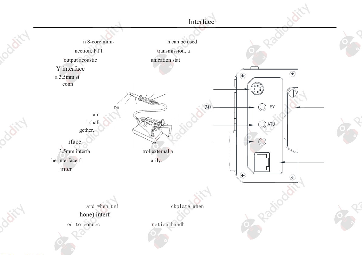
13 ATU key
Press the key in a short time to connect built-in automatic antenna
tuner to antenna port, and press the key in a long time to start the
automatic antenna tuner for tuning.
14 Po key
Press the key in a short time to adjust transmitting power under
the cooperation of major tuning knob. The adjustment range is
0.1W~5W.
15 A/B key
Press the key in a short time to switch between VFOA/VFOB.
16 < key
Press the key in a short time to move the stepping position of
current frequency to left.
17 > key
Press the key in a short time to move the stepping position of
current frequency to left.
18 V/M key
Press the key in a short time to switch between VFO mode and
MEMO mode.
Press the key in a short time to switch to a higher frequency band.
20 DN key
Press the key in a short time to a lower frequency band.
19 UP key

Panel Keys
5
21 Volume- key
Press the key in a short time to reduce current volume.
22 Volume+ key
Press the key in a short time to increase current volume.
23 PTT key
The radio will enter transmitting state by pressing and holding the key.
A T/R indicator light
It is green when under receiving state
It is red under transmitting state
The light will be red when charging under shutdown state. It will be green when charging if finished.
B DATA indicator light
It will be flickering under data communication state.
C LINK indicator light
The light will be turned on when main machine is connected with peripherals.

Left Interface
6
24 Antenna interface
BNC type interface with impedance being 500.
25 Medium frequency signal outlet
Output and receive first medium frequency signals.
26 Left bracket
Stretch it outward when using it. Fold side backplate when it is not used.
27 Earphone interface
It is a 3.5mm stereo socket (3 wires) interface used to connect earphone
devices.
*It shall be noted that functions of the interface will be different as
for different version of X5105.
28 DC power interface
It is an external DC power input interface used to connect
external DC power by using attached power lines. External
DC power supply shall be capable of supplying power
output of 13.8V@3A. The interface can be also used to
charge build-in battery.
+
-
EXT DC
24
25
26
27
28

Right Interface
7
29 ACC interface
The interface is an 8-core mini-type DIN interface which can be used for external
amplifier connection, PTT control and band signal transmission, and it can be used
to input/output acoustic signal under data communication state.
30 KEY interface
It is a 3.5mm stereo interface
used to connect manual/auto
telegram keys. Wire
connection of telegram keys
are shown below:
As for manual telegram
key, 'Dit' and 'Dah' shall
be connected together.
31 ATU interface
It is a 3.5mm interface (3 wires) used to control external antenna tuner.
*
The interface functions are not opened temporarily.
32 COM interface
It is a 3.5mm interface (3 wires) used to connect computer aided
control system and firmware update.
33 Right bracket
Stretch it outward when using it. Fold side backplate when it is not used.
34 MIC (microphone) interface
It is used to connect attached multi-function handheld microphone.
ACC
KEY
ATU
COM
MIC
29
30
31
33
32
34
Dit
Dit
Dah
Dah
Public
Public

Handheld Microphone Function
8
1. LOCK key
2. PTT key
3. Up/down
4. Transceiver
indicator light
5. Figure key area
6. FIL key
7. MODE key
8. Functional
indicator light
9. Function keys
10. MW key
11. V/M key
12. XFC key
13. TUNER key
Lock key
transmitting control key
Frequency increase/decrease key
Hand microphone operation indicator
light
Figure keyboard area
Filter selection
Selection of working mode of main
machine
No
F1/F2 custom settings key
Storage
Frequency/channel switching
Send preset message
Press it in a long time to start antenna
tuner for tuning

Description for External Interfaces
9
1、 Microphone interface
2、 CIV interface
3、 Earphone interface
4、 ACC interface
5、Wire connection of telegram keys
MIC
MDATA
GND
MIC
MICE PTT
MSVSW
NC
+8V
TXD
RXD GND
Signal
Signal GND
PTTBAND
AF_IN
AF_OUT
ALC
DATA
+8V
GND
Dit Dah Public
Dit Dah Public

Charging and Maintenance of Build-in Battery
10
X5105 has a built-in 3800mAh polymer lithium battery pack. When there is no external power supply connected, the battery pack
will supply power for the whole device. When external power supply is provided, the built-in circuit will be automatically switched to the
external power supply.
5. The maximum charging time is 10-12h. Charging will be
automatically stopped when battery is fully charged, and the
screen will display charging finishing information as shown in
right figure.
Voltage of battery is generally between 12.1~12.5V after
charging.
Charging method:
1. Enter system menu #9:Charger;
2. Rotate large knob and select 'ON', and then enable charging
function;
3. Select 'OFF' to disable charging function when operating.
4. Set voltage of external power supply between 13.5V~15.0V
and connect to the power supply port of external power source,
and then the main machine will be automatically charged.
Note: X5105 will be automatically charged and T/R indicator
light will be red when charging function is enabled and
connected with appropriate external power supply under
shutdown state. T/R indicator light will be green when
charging is finished.
Vext=13800mV
Vbat=11800mV
Charging…
Information displayed on screen when
charging under shutdown state
Vext:Display voltage of external power supply
Vbat:Display current real-time voltage of battery
Vext=13800mV
Vbat=12200mV
Charge Finish
Information displayed on screen after charging

Charging and Maintenance of Build-in Battery
11
○When battery is supplying power and almost running out, the power indicator at top right corner of screen will display ,
indicating that charging shall be carried out immediately or switching to external power supply is required. It will be normal if
the shell is slightly exothermic when charging.
○ Service life of the built-in battery is limited under normal use. Please contact with dealer to replace battery if capacity of battery
is obviously reduced or battery can not be charged (warranty period of battery is 3 months, replacement beyond the warranty
period shall be paid).
Rated voltage range of equipment shall not be exceeded when applying external power supply,
otherwise irreversible damages will be caused to equipment.
Once abnormal heating is found at the position close to battery on the back of shell, the
equipment shall be immediately turned off and equipment shall be placed at a safe and
ventilated place. Please contact us for proper disposal after confirming safety conditions.

Connection of External Power Supplies
12
13.8V external DC power supply is available for X5105. Current load capacity of DC power supply shall be 3A at least. Attached power lines
can be used to connect to radio and DC power supply.
DC power supply shall be connected in strict accordance with following figure to avoid reverse polarity connection.
White line shall be connected with the positive pole of power supply and metal-shielded line shall be connected
with negative pole of power supply.
+
-
EXT DC
POWER SUPPLY
VOLT ADJ
+-
White line
Metal-shielded line
ON
OFF
X5105

Connection of External Power Supplies
13
EMC magnet ring can be applied on power lines to prevent external disturbance from entering radio via power lines and radio-
frequency interference in radio from radiating externally via power lines when external power supply is adopted for X5105. Magnet ring
shall be installed at the side closing to battery socket.
Polarity of power lines shall be carefully inspected to avoid reverse polarity connection when external power
supply is adopted.
Limited warranty of the radio does not include damages caused by wrong connection of external power supply
or abnormal voltage.
Power line shall be twined for
2 rounds on magnet ring.
Close to interface to
greatest extent

Operation
14
X5105 adopts multi-function menu mode to enable or disable various functions. All functions are distributed in 9 menu pages, and each page of
menu has four functions that can be selected.
Menu can be switched in following methods:
Press MENU key in a short time to switch menu pages.
Four multi-function keys under the screen are
corresponding to displayed function menu.
Menu page
X5105
T/R DATA LINK
LOCK
PRE
ATT
MODE
MENU
V/M
A/B
NB RIT
ATU Po
<
Multi-function key

Operation
15
Description for functions of keys on panel
S/N Name of keys Operation
Short press Long press
1 PTT
Depend on PTT mode settings (assume that current frequency band is allowed to be transmitted):
Normal PTT mode: press to enter transmitting state and loose to enter receiving state
PTT triggering mode: switch between receiving and transmitting after every press
2 Increase volume (a large
loudspeaker icon) Increase 1 receiving volume Continuous increase of receiving volume until
loosening the key
3 Decrease volume (a small
loudspeaker icon) Decrease 1 receiving volume Continuous decrease of receiving volume until
loosening the key
4 DN Last wave band (progressive decrease of
frequency) No
5 UP Next wave band (progressive increase of
frequency) No
6 PWR None Power ON/OFF
7 PRE/ATT
Bypass
PRE ON
ATT ON
Cycle
Not available
8 MODE
Mode LSB/USB/CW/CWR
NFM/AM
Cycle
SPLT on/off
Cycle
9 NB
Impulse noise
suppressor
On/Off
Cycle
Switch battery gauge/voltmeter
to circularly display them

Operation
16
10 RIT
RIT selected/not
selected
Cycle
RIT value zeroing (no matter whether
RIT is selected or not)
11 V/M
Switch VFO/MEMO
mode
Cycle
write current MEMO parameters in VFO
and return to VFO mode if under MEMO
mode
12 <
VFO mode: move frequency stepping
position to left
MEMO mode: last channel
Execute short press operation continuously
Interval is about 0.1s
Until loosening the key
13 > VFO mode: move frequency
stepping position to right
MEMO mode: next channel
Execute short press operation
continuously
Interval is about 0.1s
Until loosening the key
14 A/B Switch VFO A/B
Cycle
Copy foreground VFO parameters to
background VFO
15 ATU Cycle of ATU bypass/access
switch
Start ATU
Enable access state after
adjustment
16 PO Cycle of output power
selected/not selected Set SWR protection threshold
17 LOCK Cycle of switch displayer
backlight level (6 levels) Keys and thumbwheel on lock panel

Operation
17
Functions of each page in multi-function menu are distributed as follows:
Menu page Functions
1
AGC RF-GAIN SQL COMP
AGC speed selection Receiving radio frequency gain adjustment Squelch Voice compression
2
DSP-FLT NR NOTCH EQ
DSP options Digital noise reduction options NOTCH options EQ options
3
MEMO MSG CALLSIGN /
Storage options Preset message Start call number settings
/
4
KEY TONE QSKTIME QSK
Options of telegram keys Sidetone settings Insertion time settings Insertion settings
5
/ DIGI SRM SWR
/
Digital communication decoder options Scanning receiver options Standing-wave scanner options
6
MIC/VOX S/P LIN/OUT PTT
MIC options Loudspeaker/earphone options Wire output/input options PTT triggering mode selection
Operation of multi-function menu shall be completed under the cooperation of MENU key and major knob:
Press MENU key in a short time: Page flip
Adjustment of functional parameters: Rotate major knob
Enter secondary menu of a certain function: Press the multi-function key corresponding to the function in a long time
Exit secondary menu Press MENU key in a short time

Operation
18
Menu page: 1
1 (common functions)
Key labels
Functions
AGC RF-GAIN SQL COMP
Short press
OFF
SLOW
FAST
AUTO
Cycle
Select radio frequency
gains.
Flickering when
selected
Rotate thumbwheel to
adjust parameters
Select noise threshold
Flickering when
selected
Rotate thumbwheel to
adjust parameters
OFF
ON
Cycle
Long press
No Restore defaults No Enter 1-4 submenu
Description of key functions:
AGC: Selection of automatic gain control speed
RF-GAIN: Receive gain settings
SQL: Noise threshold settings
COMP: Voice compression settings
LEVEL: Voice compression ratio settings

Operation
19
1-4 submenu
Key labels
Functions
COMP LEVEL / /
Short press
OFF
ON
Cycle
Select compression ratio
Flickering when
selected
Rotate thumbwheel to
adjust parameters
Long press
No Restore defaults / /
Other manuals for X5105
7
Table of contents
Other XIEGU Transceiver manuals
Popular Transceiver manuals by other brands

L3 Nova Engineering
L3 Nova Engineering NovaRoam MH902 user manual

Apache Labs
Apache Labs ANDROMEDA ANAN-7000DLE MKII user guide

Super Star
Super Star 3900 owner's manual

Vertex Standard
Vertex Standard GX2000 Alignment Guide

Sensus
Sensus 510R2 Installation Instructions-Draft

ELECRAFT
ELECRAFT K3S Frequently asked questions